Badger_McLetcher
|
| posted on 30/4/09 at 07:12 PM |

|
|
Wishbone force analysis
Hey guys, as part of a uni project I've been making a excel spreadsheet to find the stress put on a wishbone under max decel, and have hit a bit
of a problem.
Basically my lecturers have told me to take the bending stresses (calculated by My/I) into account, and that's where it falls to bits. Even
with the locost suspension and weights I'm getting forces that exceed the yield stress of steel! I am sure I havn't made any unit errors
and the lecturers were stumped.
Soo... can anyone help me or point me towards any resources on how to calculate the forces on wishbones?
Cheers,
Badger
If disfunction is a function, then I must be some kind of genius.
|
|
|
|
|
MikeR
|
| posted on 30/4/09 at 07:29 PM |
|
|
why not post your spreadsheet on here and let others have a look.
|
|
|
nasty-bob
|
| posted on 30/4/09 at 07:29 PM |
|
|
Hi,
You need to calculate the weight transfer onto the loaded wheel due to braking and cornering accelerations.
Then resolve the forces into the upper and lower wishbones by balancing forces laterally and taking moments about the contact patch.
The lower wishbone is put into compression and so you need to calculate buckling using Eulers theory after resloving forces into front and rear tubes
of the wishbone.
The upper wishbone is put in tension.
The braking loads put a forward load on the upper wishbone and a rearward load on the lower wishbone. Using upper as an example, this puts the forward
tube in compression, buckling, and the rear tube in tension.
I would only consider bending in the lower wishbone due to the damper pick up point. For this you need to consider the acceleration of the unsprung
mass going over a bump, I seen to recall a value of 8g but could be wrong.
Bit rushed,but this it how I would approach it.
Cheers
Rob
|
|
|
Badger_McLetcher
|
| posted on 30/4/09 at 07:37 PM |
|
|
Intriguing! Nasty-bob you've brought up a few couple of things I hadn't thought of (cornering weight transfer and Eulers theory).
It's really the lower wishbone I'm focussing on atm as it takes most of the load, and I've not taken into account
springing/damping.
As MikeR suggested I'm attaching the spreadsheet to this post. Be gentle!
Cheers,
Badger
If disfunction is a function, then I must be some kind of genius.
|
|
|
brianthemagical
|
| posted on 30/4/09 at 09:09 PM |
|
|
Maybe seems over complex in some places, but it could be me being too simple.
Couple of points
B21, should this not use half the upright height, rather than the BJ seperation distance.
Not sure if your breaking torque is one zero too large.
Your weight and mass are wrong/mis relationed.
Weight transfere seems too high, i'd be after double figures.
Hub torgqu is one order of magnitude too large.
I then think it goes downhill after the Wishbone force analysis, but i can't workout what you're doing with front and rear member forces
so will reserve judgement.
FOC of 10 seems overkill.
Think that's all i can see.
Another point though, don't use twisting, ever, it's torque or torsion.
If i get chance i'll do some CFD of your modle, but no promises at the moment as i'm mega busy, or at least i should be.
Hope that's of some help.
|
|
|
rachaeljf
|
| posted on 30/4/09 at 09:10 PM |
|
|
Hi there,
You appear to have calculated a bending moment using a lever arm of 0.5 metres, i.e. treating your wishbone as a cantilever 0.5 m long. No wonder your
tubes are failing!
You seem to have correctly resolved your applied loads into axial tension and compression loads in the wishbone tubes. The tube in compression is the
one subject to Euler buckling.
As well as the axial loads, the tubes are subject to local bending effects due to imperfect alignment of the tubes' axes with your supports, and
as Nasty-bob mentioned, you will get local bending due to the eccentric load from the spring/damper. The lever arm for the damper should be no more
than maybe 70 mm? I.e. it's the distance between the bottom balljoint and the damper mounting bush.
If you assume the car is braking so hard it's stood on its nose, enter a damper force equal to half the car's weight. Multiply by say 3 to
account for dynamic effects (bumps). Then multiply by 70 mm and divide by 2 to get your bending moment in each tube.
A compression strut subject to combined bending and compression is up against it as far as buckling is concerned. This will explain why lower
wishbones fail just inboard of where the damper mounting plate ends.
Hope that all makes sense, and is of some help!
Cheers R
|
|
|
Badger_McLetcher
|
| posted on 30/4/09 at 09:26 PM |
|
|
Thank you both for your help! I'm gonna get back onto it tomorrow morning and see what I can do.
It's interesting what you say about the wishbones rachaeljf, it seemed wrong to me, but that's the way my lecturers told me to do it!
Wasn't going to incorporate the dampers/springs into this project but you've got me thinking now.
And the FOC of 10 is again my lecturers. Point about the torque/torsion taken 
Cheers,
Badger
If disfunction is a function, then I must be some kind of genius.
|
|
|
rachaeljf
|
| posted on 30/4/09 at 09:44 PM |
|
|
Well, if your lecturers can't spot the problems in your spreadsheet, I'd worry about your lecturers!!!
I've had a little play with your spreadsheet, have a look and see what you think. By the way, I've tidied up your SI units and trimmed
some of the decimal places. Good presentation will score more marks!
Cheers R
|
|
|
brianthemagical
|
| posted on 30/4/09 at 10:10 PM |
|
|
Sorry about the twisting thing, just gets on my nerves abit, and probably isn't too impressive to a prospective employer.
I managed some FEA, not CFD, not usre where that came from. The maximum von mises stress is 43 MPa, with a software library defined Yield of 325 MPa
for AISI 1015. That is with the load on the apex of the two members, restraint is the mounts, load of 6927 N. It isn't the most complex of
models, but gives an idea.
On a side note, 47mm dia tube!!!!!!! Good enough for a tank.
I'll see if i can get a pic up at some point.
Resultantant force in rear wishbone, 5970 N
front, 4011 N.
[Edited on 30/4/09 by brianthemagical]
[Edited on 1/5/09 by brianthemagical]
|
|
|
brianthemagical
|
| posted on 30/4/09 at 10:17 PM |
|
|
As i said above, it is a simple model, but should be good enough.
[Edited on 30/4/09 by brianthemagical]
[Edited on 1/5/09 by brianthemagical]
 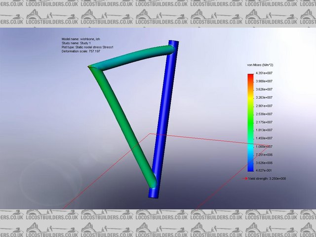
Rescued attachment wishbone, ish-study 1-stress-stress1.jpg
|
|
|
cymtriks
|
| posted on 1/5/09 at 08:27 AM |
|
|
Ok, here goes...
Stop confusing Mass and Weight.
Stop calling a weight or force a Mass and stop calling a mass a weight
tidy up your equations so that G isn't being put in and then taken out again in every other line.
I get:
B3 = 9810 N
B10 = 14172 N
B11 = 1.44 (stop quoting too many places!!)
B12 = 14172 N
B13 = 2953 N
B14 = 10629 N
B15 = 75%
B16 = 5315 N
After this your wishbone force analysis is wrong. You need to think about how you are resolving the loads that you calculate in B16 and B21 to give
the answer in B25.
I get a force on the lower wishbone of 11123 N and a force on the upper wishbone of 5809 N.
The forces don't seem to be dealt with in a clear way from then on. You have calculated the forces on each arm of the wishbone but you use the
total force on the the wisbone in your stress due to offset calcs.
The very high stresses in the wishbone tubes are usually mitigated by reinforcing the damper mounting position. Note that in the locost design this is
done by welding on a substantial plate to the lower wishbone outer end.
|
|
|
Badger_McLetcher
|
| posted on 1/5/09 at 09:48 PM |
|
|
Thanks for all your feedback guys, it's very much appreciated!
As for fee's if your at stoneleigh sunday I'll buy you a beer
Havn't had the chance to go over it today due to workload but since it's due in next thursday I'd better get me arse in gear!
Thanks again. you've all been very helpful!
If disfunction is a function, then I must be some kind of genius.
|
|
|
brianthemagical
|
| posted on 2/5/09 at 11:12 AM |
|
|
I happen to be at Stoneleigh on Sun, but i don't think it's possible to buy beer in small enough quantities, and i'm off beer due to
massive workloads and Uni deadline. 
|
|
|