StevieB
|
| posted on 17/10/09 at 03:06 PM |

|
|
The Teklam products are very similar to those offered by Ayres as used on Trev.
The advantage I see of using the composite panels over ali panels is that once the monocoque is formed, an overall skin of woven roving, carbon or
kevlar (budget allowing...) can be added to put some extra strength to the whole thing.
Obviously it will take a serious amount of planning to get it right and I though of starting with a steel speceframe to get the suspension right
first, then construct a monocwue to mount everything to.
Of course it's all an exercise in 'because I can/might be able to'....
|
|
|
|
|
ceebmoj
|
| posted on 17/10/09 at 04:02 PM |
|
|
quote:
Originally posted by nasty-bob
Hi
Honeycomb panel was supplied by Technical Resin Bonders and cost about £250 for a 8 x 4 sheet 1/2
inch core sheet.
The carbon/kevlar was from East Coast
Fibre Glass Supplies
Cheers
Rob
is who nasty bob used for his compersit shears and it looks like thay have an apropreat product for this ripe of construction
|
|
|
Benonymous
|
| posted on 19/10/09 at 10:35 AM |
|
|
The Ayres product used in TREV is a honeycomb panel with GRP faces rather than aluminium. They use epoxy resin and a woven mat. A friend who runs a
CNC routing business has a few samples.
I think a good approach with this material would be to use it partly as a structural material and partly as a core in your planning.
It would be possible to get a laminate to make a good bond with some surface prep. The choice of reinforcement I would choose would be carbon fibre.
Kevlar is an excellent fibre but it is an absolute mongrel to cut and almost impossible to sand. It fuzzes up something chronic and will drive you
nuts.
The epoxy GRP honeycomb product is substantially cheaper than the aluminium faced types and I think it would be an excellent choice particularly if
you had it cut on a large scale CNC router.
Laser cutting isn't very suitable for aluminium, youre better off cutting it with a rotating tool or a water jet. The GRP stuff could go on a
laser but the cost per hour compared to CNC routing is much higher. Any decent kitchen manufacturer would have a CNC router up to the job.
As to design, never feed a load into an unsupported face, only into a supported edge or corner. A good method would probably be to use the HC sheet
to make the length of the monocoque and steel to make bulkheads and suspension/engine/steering pickups and structures. The spaceframe components
could bolt to lugs or bobbins laminated into the structure.
The biggest downside to this is if you crash it and bust it, you'll have to replace the monocoque part completely.
|
|
|
Volvorsport
|
| posted on 19/10/09 at 05:14 PM |
|
|
youve just described how the mosler chassis is made .
it uses 1 inch teklam sheet (ally honeycomb with nomex/grp mix) , the inside is laminated with carbon and kevlar , the roof structure is carbon and
bonded to the honeycomb chassis .
the rear engine/ suspenion subframe are bolted through bobbins into the chassis as is the front .
the floor section is purposely left long to support the rear subframe as it rests on it , it bolts upwards at the front .
they use large bobbins to bolt everything in .
i cant believe how easy it all looks , a guy with a router and some straight edges could easily make it .
www.dbsmotorsport.co.uk
getting dirty under a bus
|
|
|
StevieB
|
| posted on 19/10/09 at 06:51 PM |
|
|
quote:
Originally posted by Volvorsport
i cant believe how easy it all looks , a guy with a router and some straight edges could easily make it .
That has famous last words written all over it!
I agree though - it does look really easy and I guess an easy way to get a template and refine the design is to build a mock up out of ply wood or mdf
(I prefer ply as mdf leaves nasty dust). Or maybe makind it using nidaplast depending on the cost of it.
[Edited on 19/10/09 by StevieB]
|
|
|
andkilde
|
| posted on 19/10/09 at 10:02 PM |
|
|
quote:
Originally posted by StevieB
I guess an easy way to get a template and refine the design is to build a mock up out of ply wood...
Or perhaps even use wood as your "engineered" material. Some fairly interesting sports racers were built with wooden monocoques back in
the 60s.
Isn't there a proven wooden seven as well?
Wood is cheap, easy to work with, takes glue well...
t
|
|
|
Benonymous
|
| posted on 20/10/09 at 06:24 AM |
|
|
Plywood would be the only "engineered" wood product I can think of and compared to using honeycomb as a core, it would be extremely heavy
for the thickness. Speaking of which, it's the thickness of the core that increases the strength of the panel.
Frank Costin made a super little car out of plywood, don't remember the model. He was also known to have used plywood for other projects aimed
at improving car aerodynamics.
So plywood is definately doable but not as a core so much unless your design aims can be achieved with relatively thin panels.
TREV used 20mm panels that were routed part way through, then bent at the cut, preserving the skin on the outside of the curve/radius. Using simple
jigs, the bent panels are held in place while a lamination of reinforcement was laid over the assembly. when it cures, the shape holds nice and
simple! You could do a whole centre section of a seven like this.
Properly designed and cut, you might only need two or three pieces to make the tunnel/passenger/sides part of the chassis. It would weigh a heap less
than steel tube as well.
|
|
|
StevieB
|
| posted on 20/10/09 at 03:57 PM |
|
|
A monocoque se7en using this technique should be fairly simple (famous last words...), with my thoughts being to build the cockpit and engine bay as
one with subframes front and rear to carry suspension and diff, though I ould extend the floor so that it's fully flat bottomed (and put an F1
style plank on the bottom as a sacrificial layer).
With a bit of planning, you could make it to take boywork from a normal se7en type car (whoever currently supplies locost bodywork...).
I suppose it depends on how much lighter the end result would be compared to a steel spaceframe.
I would only use plywood as a proof of concept and final template, not for the final shssis as it's too heavy.
|
|
|
Theshed
|
| posted on 20/10/09 at 08:24 PM |
|
|
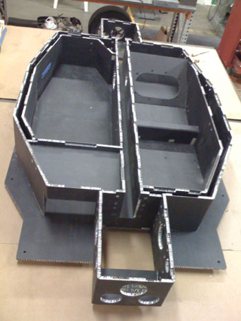
At least with carbon skins you would not have to have a love affair with rivets.........
 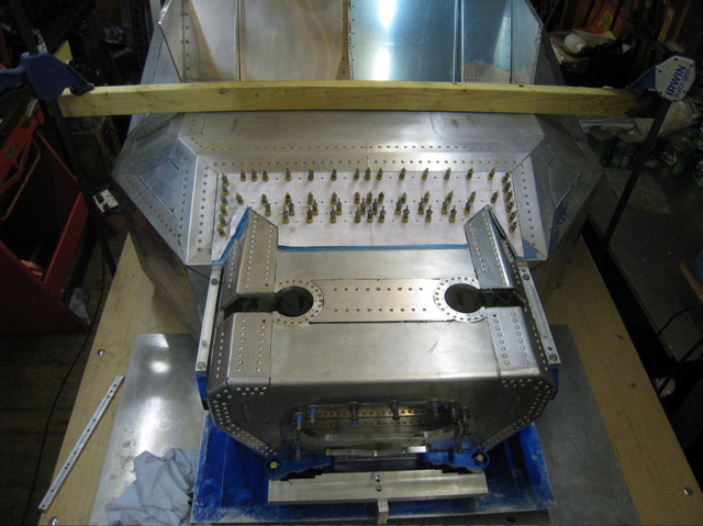
A view from above - front pinned on
|
|
|
Benonymous
|
| posted on 20/10/09 at 09:56 PM |
|
|
Very impressive ^^^^^^^^^^^^^^^
What is this a chassis for? The dedication to do all those rivets is admirable. Not forgetting of course, that every hole needs to be deburred prior
to seating the rivet. Massive time/effort.
|
|
|
Theshed
|
| posted on 21/10/09 at 10:33 AM |
|
|
Dedication....there are days when I wished the shed would burn down. Each hole is drill, debur between sheets, drill to size and debur again -
countersink for some holes - apply glue - then try and work out why all the holes have moved.....
If I started again I am not sure I would use aluminium. My tub is not that light - circa 100kg. It is probably fairly stiff and will be more so when I
add front stays to a roll hoop.
Back to the topic - I think that a carbon honeycombe tub for a 7 style car would be a lot simpler. I think that it has already been done. There is
honcombe and honeycombe so beware. It is also used for things like exhibition stands etc and designed to look pretty. Specifying 1/8" cells is a
good idea.
It is fairly easy to bond in inserts but even easier to have then bonded in when the panel is made. Yoou would need a jig - a group buy perhaps..
I have not made a great job of load paths at the front of my car and have all sorts of internal reinforcement adding to the weight. The suggestion of
tubes from the bulkhead forward would certainly simplify things - that was my plan A and I wish I had stuck with it. The rear ought to be fairly
simple though provided that there was a substantial bulkhead behind the seats.
I would make the scuttle structural - a good few layers of CF.
I would make a cardboard model 1/4 - cheeper and more acceptable on the kitchen table. Then a wooden full size model.
I would endorse the suggestion of a cnc router - I did mine by hand...awful!
Given that a measuring error would not be reversable I would gather together all of the bolt on bits before bonding anything.
|
|
|
ceebmoj
|
| posted on 21/10/09 at 12:04 PM |
|
|
quote:
Originally posted by Benonymous The choice of reinforcement I would choose would be carbon fibre. Kevlar is an excellent fibre but it is
an absolute mongrel to cut and almost impossible to sand. It fuzzes up something chronic and will drive you nuts.
As i under stood it in treve the Kevlar is used to make the floor and interior puncture resistant. Will CF offer the same benefits?
also does the GTM use CF / kevlar in its tub? Looking at a number of resources on line it looks like it would be more efisent to use a mix of fabrics.
|
|
|
Benonymous
|
| posted on 22/10/09 at 02:37 AM |
|
|
Kevlar would definitely be the best choice for puncture resistance and if you just cut a section that had no need to be trimmed and put it in the
layup, it wouldn't provide you with too much grief. CF would not give you the same properties as Kevlar but I don't see it as being a
major problem if you had a 20mm panel and CF reinforcement it would be more puncture resistant than say an aluminium floor.
|
|
|
ceebmoj
|
| posted on 22/10/09 at 12:16 PM |
|
|
hi,
this is my attempt at some cad of a tub all 20mm core to be covered in resen and fabric what do people think?
Its a 60s inspired single seater. the curved side panels will be lade up seporatly then bonded on to the tub
 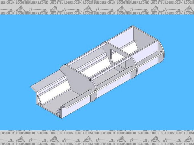
compersit tub
[Edited on 22/10/09 by ceebmoj]
|
|
|
Theshed
|
| posted on 22/10/09 at 01:13 PM |
|
|
Is that rear engine - feet through the window of the middle bulkhead?
I would try to design out the small fillet on the inside bottom.
Where are your suspension loads going?
One thing I think I got right is a fully stressed seat base - a fully stressed back would help.
Are you aiming for a semi stressed engine but a fully stressed gearbox? If so you need to think how you will attach your engine plate/adaptor. You can
have inserts bonded in when the panel is made.
A 60's style car gives you a nice choice of transaxles if you go for engine in the back - Hewland Mk 9 boxes are very reasonable.
|
|
|
ceebmoj
|
| posted on 22/10/09 at 03:04 PM |
|
|
quote:
Originally posted by TheshedIs that rear engine - feet through the window of the middle bulkhead?
Yes that the idea.
quote:
Originally posted by Theshed
I would try to design out the small fillet on the inside bottom.
I put the filet in there so that there would be plenty of contact patch to glue the triangle to the floor with like the trev project. I also left the
end cap of to show the detail
quote:
Originally posted by Theshed
Where are your suspension loads going?
I have marked the rear suspension points on the new picture
 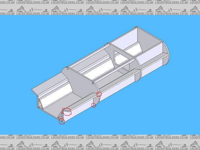
compersit tub suspention point
quote:
Originally posted by Theshed
One thing I think I got right is a fully stressed seat base - a fully stressed back would help.
I have been trying to incorporate a stressed back but want to put my fuel tank between the seat back and the rear bulkhead so was going to have
another bulkhead with a window in it so that I can still get access to the fuel tank by removing an alloy panel.
quote:
Originally posted by Theshed
Are you aiming for a semi stressed engine but a fully stressed gearbox? If so you need to think how you will attach your engine plate/adaptor. You can
have inserts bonded in when the panel is made.
A 60's style car gives you a nice choice of transaxles if you go for engine in the back - Hewland Mk 9 boxes are very reasonable.
Not sure if I will go stressed box i'm considering using a bike engine and just hanging a car diff out the back having a plate the diff mounts to
and the rear suspension pick up points are on that its then bolted on to the Tub
[Edited on 22/10/09 by ceebmoj]
|
|
|
StevieB
|
| posted on 23/10/09 at 09:20 PM |
|
|
That looks good to me - would you do the outer skin with honeycomb as well?
I need to get a copy of CAD in order to plan out my own design! Looks much neater than my hand sketches 
|
|
|
ceebmoj
|
| posted on 24/10/09 at 04:52 PM |
|
|
I was thinking of just laying up the side panels out of two layers of cloth and resen with a gell cote and then bonding them on to the tub.
my uprights are out being machined at the moment so after that I will make up a MDF tub and do a build up with that
|
|
|
Ferg
|
| posted on 24/10/09 at 06:45 PM |
|
|
quote:
Originally posted by ceebmoj
also does the GTM use CF / kevlar in its tub?
No.
The Libra and Spyder tubs are purely GRP with the exception of two 2" steel plates which are the upper seat-belt mounts. Otherwise......nothing
but GRP and the Gelcoat.
|
|
|
Uryen
|
| posted on 25/10/09 at 08:43 AM |
|
|
quote:
Originally posted by Theshed
Are you aiming for a semi stressed engine but a fully stressed gearbox?
Could you explain what this means?
Does it mean the engine and box are part of the frame structure like in some extruded aluminum bike frames?
|
|
|
StevieB
|
| posted on 25/10/09 at 09:29 AM |
|
|
quote:
Originally posted by Uryen
quote:
Originally posted by Theshed
Are you aiming for a semi stressed engine but a fully stressed gearbox?
Could you explain what this means?
Does it mean the engine and box are part of the frame structure like in some extruded aluminum bike frames?
Pretty much the same principle, yes.
If you have a look at the beack end of a formula fors, the gearbox carries the rear suspension and the whole rear end is supported by the
engine.
 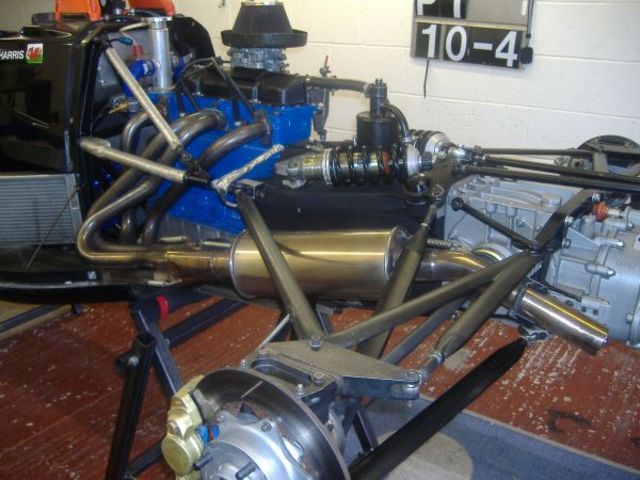
Rescued attachment ff engine.jpg
|
|
|
Theshed
|
| posted on 1/11/09 at 10:25 AM |
|
|
Yup that's what I meant ^^ What I meant by "semi stressed" was that the engine would be solid mounted but braced by some part of
your composite structure.
I would think about a nice big plate across the back of the structure to tie everything together.
Excellent plan to start with the uprights and work inwards.
If you look on GT40s.com in the build logs you will see somebody building a carbon tub using mdf to make moulds etc
John
|
|
|
aitch
|
| posted on 2/12/09 at 07:53 PM |
|
|
lower cost but more labour
composites or 2 layers of structural material (aluminium, fibreglass carbon fibre whatever) sandwiching a spacing material are far stronger and
lighter than the moulded fibreglass type construction.
using woven glass and epoxy resin sandwiching foam will be far cheaper than the honeycombe materials although forethought and planning is paramount as
reinforcing needs to be built in rather than just bobbins as the foam material will crush more readily.
Its also easy to produce curved components.
The processes are very well documented in the kit aircraft market, i believe the techniques originally pioneerd by Burt Rutan and used in many of the
worlds most popular and numerous homebuilt aircraft
aitch
p.s. new here and thinking aloud please be gentle with me
[Edited on 2/12/09 by aitch]
[Edited on 2/12/09 by aitch]
|
|
|
aitch
|
| posted on 3/12/09 at 12:03 PM |
|
|
too much time on my hands
Ive re-read this whole thread and the links
the Nidaplast cores are very interesting, i would be more concerned about heat resistance than strength, however these cores would make possible a
locost composite chassis that is TRULEY LOW COST more expensive aluminium honeycombe could be used in the areas that need the heat resistance, id opt
for woven glass and epoxy over most of the structure to keep costs reasonable, although carbon and or kevlar could again be used in some areas either
for strength, puncture resistance or asthetics
http://www.cfsnet.co.uk/acatalog/Nidaplas_Polypropelene_Core.html they also provide links to use and application of the core material which would be
invaluble in planning the build
The Palatov Chassis uses composites to create a series of box sections, a technique which followed will create incredibly strong and rigid
structures
aitch
im going to use some of this time to come up with a concept
[Edited on 3/12/09 by aitch]
|
|
|
aitch
|
| posted on 3/12/09 at 12:08 PM |
|
|
good pic of the palatov chassis
as it says good pic of the palatov chassis showing the box sctions created
aitch
Rescued attachment dp1017.jpg
|
|
|