Badger_McLetcher
|
| posted on 5/12/09 at 01:57 AM |

|
|
Custom Chassis
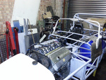
I would quite like opinions on the current version of the chassis for my project. Bear in mind it is larger than a lotus and expected to handle quite
a bit of power (500 bhp standard).


I've left diagonals and shear panels off for clarity in these pics, but can anyone see anything horribly wrong with it? I wanted an integral
roll cage, but this is proving difficult and is going to have to be welded in later!
Cheers,
Badger
If disfunction is a function, then I must be some kind of genius.
|
|
|
|
|
kennyrayandersen
|
| posted on 5/12/09 at 03:24 AM |
|
|
Besides the missing diagonals? Lol
Pretty much you whole aft box doesnt line up with anything. Where do those loads go? They must be reacted in bending by the upper and lower
inbd/outbd members which makes the load path softer and the stresses higher.
I also suggest rethinking the concept of the roll bars as part of the chassis as it would really ad a lot of robustness as compared to tacking
something on after the fact.
Also, where is the torsional continuity from the front suspension back trough the engine compartment and onto the rest of the chassis? You might show
the diagonals now that youve presented the basic layout (you might remove the engine for clarity).
|
|
|
scutter
|
| posted on 5/12/09 at 08:05 AM |
|
|
 
I feel this would be a start, plus a full cage tied into the back of the engine cradle.
Atb Dan.
The less I worked, the more i liked it.
|
|
|
steve m
|
| posted on 5/12/09 at 09:06 AM |
|
|
Which way does it go ??
|
|
|
Badger_McLetcher
|
| posted on 5/12/09 at 10:35 AM |
|
|
Steve m: Big block at the front mate 
kennyrayandersen: The problem with the aft section is that that is pretty much the only shape I can get it to fit the bodyshell, I was hoping I can
mitigate the bending effects by creating a sheet steel triangular brace to fit between the drive tunnel and the front face of the rear snout (inside
the compartment). Also the bracing on the rear snout/diff carrier is meant to feed the loads into/from the rear corners. Not a particularly satisfying
concept but the best I can think of.
I've enclosed a couple of pics of the chassis with diagonals, and an earlier version with the integral roll cage (this one is unfinished).


If disfunction is a function, then I must be some kind of genius.
|
|
|
MakeEverything
|
| posted on 5/12/09 at 10:41 AM |
|
|
Upload the picture with all of the diagonals, as i suspect most of your responses will be regarding strength and triangulation / load issues.
As above, an integral roll cage woundnt be difficult to design. Think of a "Four Poster" Bed, and youre half way there. The main part of
the cage, should be on all four corners of the cockpit, which will then allow you to design the rear and front sections.
It looks good at a glance, but the diagonals included would give a better idea.
There are a coouple of braces that i dont see necessary, but again, without the diagonals is difficult to identify their purpose.
Kindest Regards,
Richard.
...You can make it foolProof, but youll never make it Idiot Proof!...
|
|
|
MakeEverything
|
| posted on 5/12/09 at 10:45 AM |
|
|
D'oh, beat me to it.
The member at the top of the rear bulkhead in front of the engine needs bracing? If not, the rear lends itself to hinge forward at the top of the
engine compartment??
Is all that metal necessary? There seems to be duplication at the rear of the engine compartment.
Kindest Regards,
Richard.
...You can make it foolProof, but youll never make it Idiot Proof!...
|
|
|
MakeEverything
|
| posted on 5/12/09 at 10:47 AM |
|
|
Read that backwards, i thought it was rear/Mid engine!!
Kindest Regards,
Richard.
...You can make it foolProof, but youll never make it Idiot Proof!...
|
|
|
Badger_McLetcher
|
| posted on 5/12/09 at 11:16 AM |
|
|
To be fair I did all the triangulation in a bit of a hurry last night, some of those are to be shear panels and pretty much all of the bracing is to
be something like 20mm sq section, not the 25mm I've used here.
There are a couple of points I've not triangulated- the one you spot because I'm not entirely sure of the best course (I was leaning
towards a simple cross brace but that wouldn't support the members in the middle). The others is cause I missed them to be honest!
The design of the roll cage isn't the problem, the problem is getting it made (accurately), since a) I'm short of money and b) I want to
make as much as I can of this myself.
edit:
I was gonna say since I changed the height of the diff carrier I've found it hard to tell which end is which myself!
[Edited on 5/12/09 by Badger_McLetcher]
If disfunction is a function, then I must be some kind of genius.
|
|
|
02GF74
|
| posted on 5/12/09 at 01:04 PM |
|
|
it is all fine and dandy putting in diagonals everywhere but you need t consider how you will get at the insdie corners in order to weld it.
the chassis with all the diagonals looks almsot sloid i.e. heavy and probbly has more diagonals/memebner than required.
unless you know what you are doing, then build up a scale model in balsa and see what effect the struts have. then you can go to the computer and
play.
why reinvent the wheel? there are proven chassis out there - thake one of those and adjust to your requirements.
|
|
|
deezee
|
| posted on 5/12/09 at 01:16 PM |
|
|
Throwing all those diagonals in there kinda indicates that you have no idea where the loads and stresses are going. Looks well OTT and enormously
heavy. Can't you just get a photo of a similar production frame and use it as a template to work from?
Bear in mind that if you make it as it stands, during a collision the only space for your rock hard spaceframe to go is into the passenger
compartment! Most chassis are built to bend and distort to save your life.
|
|
|
Badger_McLetcher
|
| posted on 5/12/09 at 01:47 PM |
|
|
02GF74: Getting at the inside corners should be ok providing that I construct this in the correct order.
Weight estimates are at about 105kg with the heavy bracing, which aint too bad considering. The scale chassis idea is a good one, which I have said
myself, I just want ideas atm.
Why not use/adapt a current design? Well firstly I looked at that possibility and wrote it off due to the shape of the bodyshell- it's a PITA
and tbh I wish I had never got it, but it's too far down the line to change. Secondly it would kinda negate the whole designed/built by myself
thing wouldn't it 
deezee: I must confess I just shoved the diagonals in last night to get a bit of an idea, but I rather thought that having everything triangulated
was a good thing!
There will be front and rear sections to act as crumple zones, but I take your point as to designing in weaknesses. Any ideas?
If disfunction is a function, then I must be some kind of genius.
|
|
|
mr henderson
|
| posted on 5/12/09 at 03:46 PM |
|
|
We can't even start to consider this chassis until we see where 4 points at which the loads are going to start towards the ground, in other
words, the upper mounting points for the spring/shocks (unless you are using a rocker system).
I can't at the moment see where those could possibly be.
Also it appears that the footwells are going to extend down the side of the engine? Surely not?
|
|
|
gottabedone
|
| posted on 5/12/09 at 04:10 PM |
|
|
Dan,
Have a butchers at the LocostUSA site as they have fitted loads of v8's to seven and seven derived chassis. Mr H has commented on the footwells
- is your chassis really this wide?
Steve
|
|
|
Badger_McLetcher
|
| posted on 5/12/09 at 04:45 PM |
|
|
OK, I can see I'm going to have to have a bit of a rethink on some of the stuff here, but that was rather the point of posting it!
Mr Henderson: The points are rougly about the grey lines, which are the axle lines. My intent for the fronts was to put the mounts on the second
vertical from the front with a reinforcing gusset connecting it to the other tubes. The rear was going to be roughly the same, but being stupid I
haven't put it in there!
For the final question, yes the footwells go down the side of the engine bay. If I had any choice in the matter I wouldn't have done this, but
unfortunately the dimensions of the car mean if I hadn't done that the car would only be suitable for driving by midgets like me. Unless I put
the engine in front of the axle line, which I really don't want to do.
The chassis is at it's most 1.37m wide, with the drive tunnel taking up a lot of space due to the size of the gearbox (again a necessity).
Please keep the advice coming in, just keep it constructive lol.
If disfunction is a function, then I must be some kind of genius.
|
|
|
kennyrayandersen
|
| posted on 6/12/09 at 05:23 AM |
|
|
quote:
Originally posted by Badger_McLetcher
Steve m: Big block at the front mate
kennyrayandersen: The problem with the aft section is that that is pretty much the only shape I can get it to fit the bodyshell, I was hoping I can
mitigate the bending effects by creating a sheet steel triangular brace to fit between the drive tunnel and the front face of the rear snout (inside
the compartment). Also the bracing on the rear snout/diff carrier is meant to feed the loads into/from the rear corners. Not a particularly satisfying
concept but the best I can think of.
This may be a limitation to weight saving, but these areas would still either need to be gusseted or a secondary member used to connect that to the
main body. You cant have the rear members just t-boning into the tub willy nilly and unsupported (unless those members are robust enough to react
those loads in bending (which BTW, isnt particularly stiff)).
|
|
|
ettore bugatti
|
| posted on 14/12/09 at 08:17 PM |
|
|
I think it is over done.
The footwell and bulkhead could be made lighter and stronger. I would fabricate a sheetmetal bulkhead with some RHS to support it.
You are now just creating the next Eifel tower.
I would make it more like a ladderframe, start with 100x50x3mm put a rollcage on it 50x2mm and construct from 3mm sheetmetal a crossmember to support
the front suspension.
Then you can put a connection (round 30mm)between the crossmember and the bulkhead.
BTW are you planning to use McPherson struts at the front?
|
|
|