Jermyn
|
| posted on 1/2/05 at 10:50 PM |

|
|
DOORS
I have a feeling I know the answer to this question before I begin.
Has anyone altered Chassis design to make provisions for doors? Does anyone think it's possible without greatly compromising the integrity of
the chassis? Ideas...Thoughts......Drawings??????
If life is a race do you want to be the first one to finish?
|
|
|
|
|
zilspeed
|
| posted on 1/2/05 at 11:00 PM |
|
|
Two words
Stephen Gusterson 
|
|
|
chunkielad
|
| posted on 1/2/05 at 11:02 PM |
|
|
I'm afraid I don't think the book chassis is going to cope mate as to get a door in, you'd have pretty much no sides!!! You could
alter the design to have a solid roof area which would take the 'strain' as it were but then you won't have a seven anymore and
would be designing a new car from scratch.
|
|
|
mangogrooveworkshop
|
| posted on 1/2/05 at 11:18 PM |
|
|
http://www.locostbuilder.co.uk
|
|
|
chunkielad
|
| posted on 1/2/05 at 11:46 PM |
|
|
I am obviously wrong!!!
Nevermind!!!
|
|
|
smart51
|
| posted on 2/2/05 at 12:01 PM |
|
|
you could have doors so long as you keep the 13 inch "sill". By doors I'm talking about permenant side screens.
The real problem is the width of a 7. your elbow prety much hangs outside the car. if you fit doors then you have nowhere to put your arm
|
|
|
Dale
|
| posted on 2/2/05 at 01:11 PM |
|
|
I am considering half doors attatched to the scuttle. These would be cruved down from the top of the scuttle and ending just before your forearm
while resting your elbow on the side. Since I will be going with a raked /split windshield it may be possible to use lexan/polycarb to add a wrap
around wind deflector to the half doors that would blend right to the screen.
Dale
|
|
|
Jermyn
|
| posted on 2/2/05 at 04:03 PM |
|
|
quote:
Originally posted by smart51
you could have doors so long as you keep the 13 inch "sill"
The real problem is the width of a 7. your elbow prety much hangs outside the car. if you fit doors then you have nowhere to put your arm
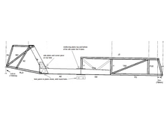
I see what you mean about the "sill" but do you really think it needs to be a full 13"? Im thinking if I use larger stock (like 2x2
RHS) and triangulate the floor to absorb the additional stresses I could probably have a 4-6" triangulated sill. (See the pic.)
Also, I'm not to worried about the width as I am building a wider-than-normal car.
Another Idea would be to build a full roll cage tying the firewall/A-posts in with the B-posts and shock towers. Anyone fancy that idea instead?
All you weight-minded locosters are grimacing at the amount of weight this would add but I'm building my car for the street, not track.
Aestetics are important as well as speed.
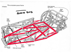 
Rescued attachment mods1.jpg
If life is a race do you want to be the first one to finish?
|
|
|
Dale
|
| posted on 2/2/05 at 04:56 PM |
|
|
I would think that unless your going IRS you will need to make your sill a minimum as high as the upper trailing arm bolt. If not then under hard
acceleration you would cause damage.
Dale
|
|
|
Jermyn
|
| posted on 2/2/05 at 05:21 PM |
|
|
How about if I used aluminum rear trailing arms off a triumph tr6? They just bolt directly into the lower chassis member, thus transferring the
stresses there.
No need to have the upper b-post mounts then.
If life is a race do you want to be the first one to finish?
|
|
|
krlthms
|
| posted on 4/2/05 at 04:30 AM |
|
|
Hello Jermyn,
I suggest you don't mess with the chassis around the sides of the cabin. Because the cabin , for obvious reasons, is an incomplete box, it is
already torsionally compromised, so you you want to keep as is. Moreover, the length of tube H in the book chassis is 11", add to that the
widths of tubes N1 and A1 (1" each), then add ride height (6" in the original Lotus 7, but most Locosters use 3.5 to 5" , and you have
at most 18", knee high to a grass hopper! I mean this 18" compares well with the height of the sill that you have to step over in a nornal
sedan. So, the door should, in my opinion, go ABOVE, the N1 tube. , and you have
at most 18", knee high to a grass hopper! I mean this 18" compares well with the height of the sill that you have to step over in a nornal
sedan. So, the door should, in my opinion, go ABOVE, the N1 tube.
There are some nice implemntations of doors on sevenesque cars:
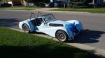
1. Look at Donkervoort, the Dutch makers. Google the name and then select the image function in Google to see examples. Briefly, what they did was
to have a hefty windscreen frame (it looks carbon fiber) analogous to an "A" pillar in a normal car. They then make a lightweight composite
door from this pillar. The door opens Countach-like. I think it looks pretty sexy, especially viewed from front when both doors open (sort of
Doberman-ear like).
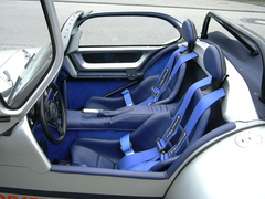
2. The German maker RCB77 attaches doors in a conventional manner; these give the car a hot rod look; again not too shabby.
3. In the Champion book, bottom picture of page 182 is shown a design of a full rollover cage, that can take gull wing doors.
I am going to try to attch a couple of pics, but, since I have never done this before (see waht you got me into ) it may or may not work.
Good luck and keep the sketches coming.
Cheers
KT (in sunny Chicago)
Rescued attachment donkervoort.jpg
|
|
|
krlthms
|
| posted on 4/2/05 at 04:31 AM |
|
|
Ha,
it worked, so here is the other one.
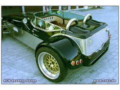 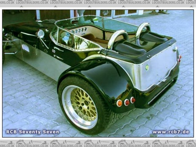
Rescued attachment rcb6_20l.jpg
|
|
|
Jermyn
|
| posted on 4/2/05 at 03:56 PM |
|
|
I see what you mean about the height factor. and the H tube. My concern was weakening the chassis too much by removing that area.
I really like the first picture. Interesting how they use that snap-flap to keep the doors closed instead of some sort of internal latch system.
Thanks for the pics and the website info. I hadn't checked out the new Donkervorts. Most of the Seven books I own have older pics.
If life is a race do you want to be the first one to finish?
|
|
|
jestre
|
| posted on 4/2/05 at 04:42 PM |
|
|
would building the doors to fit the open space snuggly with triangulation truely cause weakness?

|
|
|
Liam
|
| posted on 4/2/05 at 06:28 PM |
|
|
Doors like that would stop the bending of the chassis but wouldn't restore the torsional rigidity as they are not connected. Also, if they fit
snuggly you wouldn't be able to open them since the chassis bending will clamp them in.
If you could open the doors then they will obviously not be doing anything structurally.
Liam
|
|
|
Liam
|
| posted on 4/2/05 at 06:30 PM |
|
|
If you're having full bodywork over the chassis, could you not have largebox section sills - like a lotus elise? Something like 6x6 box section
suitably tied in to the rest of the chassis.
Liam
|
|
|
krlthms
|
| posted on 4/2/05 at 08:49 PM |
|
|
quote:
Originally posted by Liam
If you're having full bodywork over the chassis, could you not have largebox section sills - like a lotus elise? Something like 6x6 box section
suitably tied in to the rest of the chassis.
Liam
There are people in this forum who really know about this kind of stuff; no doubt they will weigh in. However, what I have learnt from previous
similar discussions, is that you have to decide whether you are building a space frame or a ladder type chassis. The space frame depends on extensive
tringulation, whereas the ladder depends on massive cntral structures. Due to obvious practical limtations, the cabin has hardly any tringulation to
start with, so removing tubing and replacing it with bigger tubing but lower down would not help. I think..?
|
|
|
Jermyn
|
| posted on 4/2/05 at 09:18 PM |
|
|
Hybrid Chassis....The answer??
I figured building a mix of a ladder frame and space frame will allow for the open door section. (if i decided to do the doors)
Developing a mix of the two applications in theory and testing them with models is not beyond my skill level. However, this method would not be
reliably accurate.
Realistically, they would need to be built or engineered through some sort of design/test program which I have no access to or knowledge about. Plus,
I'm not trying to spend 10 years designing a chassis just so I can have doors.
On the other hand, plenty of autos have been built on unreliable engineering ideas that have been successful. Space frame and ladder frames both have
benefits. Why not make them both work in a hybrid sort of chassis. Who's building a hybrid sort like this now?
If life is a race do you want to be the first one to finish?
|
|
|
cymtriks
|
| posted on 5/2/05 at 05:29 PM |
|
|
I'd suggest a 4x2-14g (minimum size) sill replacing tubes D1/D2, A1/A2 and K3/K4.
Omit tubes TR5/6, N1/N2, M1/M2, K1/K2 to make way for the doors.
This will restrict footwell space a bit as the 4x2 is a lot chunkier than the book 1x1 tube so I'd suggest going the wide chassis route as in
the Mc Sorley plans.
Also the book trailing arm arrangement won't be possible with this mod. You could opt for a Westfield style rear double wishbone layout.
A live axle or Deon would be possible if you continued the 4x2 approximately where tubes W1/W2 are in the book which would give a solid pick up point
for upper leading arms. Lower links could be leading to give a "book backwards" layout (Marcos used to use this layout on the V8 Mantula
cars) or you could use two lower links going forwards from the axle ends angled inwards to meet the bottom of tubes e and f (which will need to be in
1x1, not 3/4x3/4, if you feed suspension loads into them). This will only work well if you can make the angle of the lower tubes to the axle line
greater than 30 degrees, probably only possible with swept back pickups on a Deon tube.
If this is compatable with your ideas then I'll plug the version of the above mods you decide on into my analysis and tell you what it does, or
doesn't do, for stiffness.
By the way, stiffening up the floor isn't going to help much if you cut out the side tubes.
|
|
|
Jermyn
|
| posted on 7/2/05 at 04:17 PM |
|
|
Cymtriks,
I was thinking more along these lines. Mcsorley 442 chassis.
Omit N1, N2, TR6 and TR5.
Make A1, A2, B1, B2, H1 and H2 all 4x2.
X brace the box section with TR4 and TR3.
Move M1 and M2 Back to converge 90 degrees with B1.Make them 4x2 also
Change the angle of the lower sections of K1 and K2 to be more angled like TR5 and TR6. This will result in a slanted rear of the door but will
provide that needed triangulation.
What do you think about that?

If life is a race do you want to be the first one to finish?
|
|
|
Jermyn
|
| posted on 7/2/05 at 04:19 PM |
|
|
sorry,
forgot to mention:
westfield-type dual wishbone rear suspension setup
If life is a race do you want to be the first one to finish?
|
|
|
cymtriks
|
| posted on 7/2/05 at 07:55 PM |
|
|
Jermyn,
Check clearance for the gearbox, propshaft and diff with 4x2 tubes if you use this size for B1 and B2.
I think you've got the general idea, that you you need to carry the 4x2 tubes into the spaceframe a bit to make certain that the loads find
their way into the sills.
Any loads fed into the H1/2 tubes will have to go round a sharp corner, 90 degrees, to get into the sills which is why I chose to continue the 4x2
sill tubes along D1/2.
Regarding the rear of the doors how about having the sills run to tube B1 as you suggest and having a 4x2 tube going from the bottom of where tubes
M1/2 are to tube O. K3 and 4 then provide triangulation.
Regarding X bracing the TR3/4 positions you'd probably get the same result by increasing these tubes to 1 inch round or to 1 inch square.
|
|
|
Jermyn
|
| posted on 7/2/05 at 09:59 PM |
|
|
Sounds like it might work Course, the whole thing might fold in half.
Can you make the mods and plug it into your program? I'm really interested to see if it will work.
If life is a race do you want to be the first one to finish?
|
|
|
cymtriks
|
| posted on 9/2/05 at 10:59 PM |
|
|
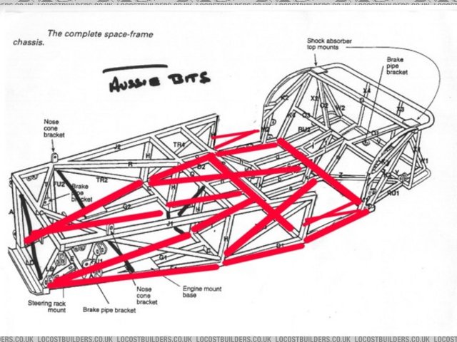
some results
I've attached a picture.
By the way Liam is right. Big sills are best.
I put 4x2 14g (approx 100mm x 50mm 2mm wall) tube into the model as shown. The K3/4 tubes were so close to the seat back 4x2 tube that I've not
shown it in the picture, it didn't carry much load anyway whn I ran the model.
The biggest stresses turn out to be the tube bendiing sideways at the rear kink hence the side reinforcing plates and vertically at the door front
hence the top and bottom plates.
When you apply, admitedly always a guess, the suspension loads of 3g bump and a safety factor of two you are at the limits of the tubes. I've
suggested some reinforcements in the picture.
As a comparison many Cobra replicas are made of 4x2 but with 1/8 inch wall (a bit more than 3mm). So a typical Cobra chassis has just over 50% thicker
walled tubes and the finished car weighs a bit over 50% more. And Cobra chassis handle 5.7 liter engines with over 400 bhp which is about triple a
typical locost.
The stiffness was 1150ftlbs per degree compared to 1180 for the book chassis. The weight estimate was 199 lbs compared to the book chassis of 181 lbs
(16g floor in steel). So it's a bit heavier and very slightly less stiff.
 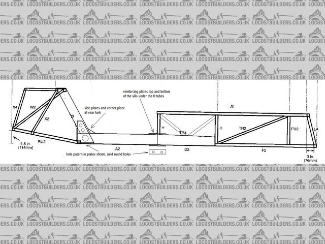
Rescued attachment locostdoors.jpg
|
|
|
Jermyn
|
| posted on 10/2/05 at 08:02 PM |
|
|
Thanks
Looks good. I'm thinking I will try to build some balsa wood models
If life is a race do you want to be the first one to finish?
|
|
|