jestre
|
 posted on 12/3/05 at 08:07 PM posted on 12/3/05 at 08:07 PM |

|
|
Calling all using MK1 RX-7s....
were you able to use the front hubs/spindles? if so, can you me out with wishbone design?
here is what I have
rx7hub
|
|
|
|
|
madman280
|
| posted on 12/3/05 at 09:02 PM |
|
|
Working on exactly the same thing as you. Using a sereis one RX7. I like the design of Darrens GTS control arms and am coresponding with him for
details and possiblities. I'm in southern ontario..so not so far away from MI. Could post a few picture if anyone is interested.
CJ
|
|
|
jestre
|
| posted on 13/3/05 at 06:11 PM |
|
|
Any pics would be much appreciated
|
|
|
madman280
|
| posted on 16/3/05 at 01:51 AM |
|
|
Here's the strut after its been stripped and the top part of the tube cut off. You'll need to remove the strut insert and drain the oil out
first. The silver part above is the machined cap that'll be welded to the top of the strut. I still need to cut the strut down further after I
determine the proper length. The manufacters specification for the King Pin Inclination is 10 degrees and 44 minutes with 13 inch wheels. The original
front track width is 56", the rear 55" using the original 13" aluminum wheels.
Image deleted by owner
[Edited on 16/3/05 by madman280]
|
|
|
madman280
|
| posted on 16/3/05 at 02:51 AM |
|
|
Heres the machined caps. They're a tight fit into the strut and will be welded on. The top portion is threaded 3/4" for a bolt or cap screw
to hold a 3/4" rod end, as the upper ball joint. I'l use a seal designed for rod ends to keep out the dirt and make them last a bit
longer.
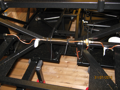 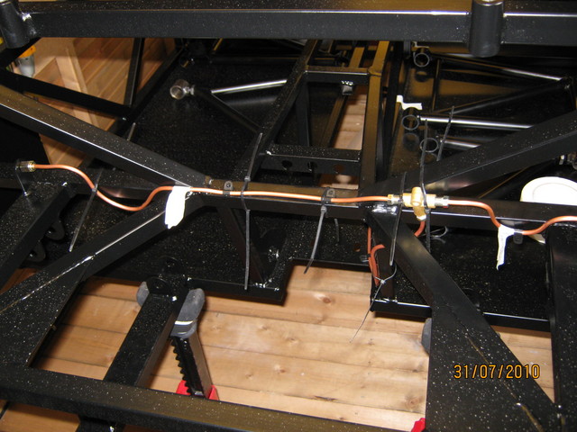
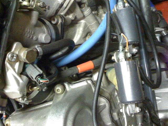
rear brake pipes first fix
[Edited on 16/3/05 by madman280]
|
|
|
madman280
|
| posted on 16/3/05 at 02:54 AM |
|
|
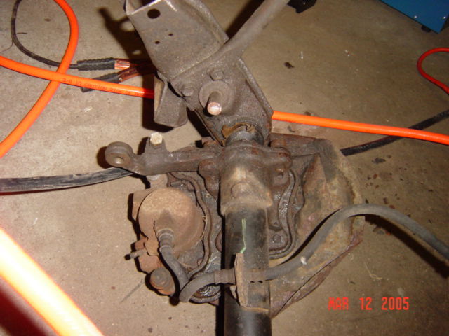
Here's the steering arm that bolts to the bottom of the strut. You can see how the ball joint fits into it. the other hole is for the outer tie
rod end. The steering stop can be ground off smooth.
side
|
|
|
madman280
|
| posted on 16/3/05 at 03:00 AM |
|
|
Another look at the ball joint without a boot. Nice and strong, as it also carries the load of the sway bar which is shown bolted to the lower control
arm in your picture. It's designed to carry a load in both directions. In case there are any concerns of using it to carry a load in an opposite
direction as it was originally used, the load from the sway bar can be equal or greater than the vehicle mass when the oposite wheel is off the
ground. Its designed with this in mind. I'm told 3 to 5 g's is the design parameter normally used.
pipe
[Edited on 16/3/05 by madman280]
|
|
|
madman280
|
| posted on 16/3/05 at 03:05 AM |
|
|
Here's a shot of the machined rings that'll be welded to the lower control arm to hold the ball joint. They're a press fit, just like
in the original control arm.
Image deleted by owner
[Edited on 16/3/05 by madman280]
|
|
|
madman280
|
| posted on 16/3/05 at 03:14 AM |
|
|
Here's a picture of the type of control arms Darren makes at GTS. Quite nice and made with oval tubing. They're made of much beefer material
than the locost 3/4" round arms. I hope Darrin doesn't mind me posting them. A bit of a advertisement for him maybe, but they are nice. The
large hole in the plate at the end of the lower control arm is where the ball joint rings will be welded on. The gold piece in the end of the upper
control arm is where the 3/4 rod end will be threaded to with a lock nut. It'll be the upper ball joint.
Image deleted by owner
[Edited on 16/3/05 by madman280]
|
|
|
madman280
|
| posted on 16/3/05 at 03:37 AM |
|
|
Heres another shot of Darrens GTS front suspension using a slightly different strut type spindle (Sierra or XR4Ti I beleive)). Its from his site
which, again I hope he doesn't mind. My car is far from finished, most of this is what I intend to use. I still have a ways to go, but I have a
clear idea of what I want to do. Its just a matter of details now. I'm working on computer modeling the front suspension to find the control arm
lengths , the height of the strut and the correct roll center to use with the RX7 live axle and hopefully the original book chassis pivots. I'll
be making the control arms a bit longer than the books to match the original RX7 track width. I welcome any sugestions, comments, or questions.
Image deleted by owner
[Edited on 16/3/05 by madman280]
|
|
|
madman280
|
| posted on 16/3/05 at 04:43 AM |
|
|
Will post a few more pics in a day or so when its bright enough outside to see the rest of the car. That is if everyone isn't sick of my crappy
photographic skills 
|
|
|


