robertst
|
 posted on 21/8/06 at 12:38 PM posted on 21/8/06 at 12:38 PM |

|
|
Problems with brackets
i have realized that i welded Fu1 and 2 in the right places but they are way off with respect to LC and LD so the wishbones would not be parallel to
the front line of the car.
let me explain:
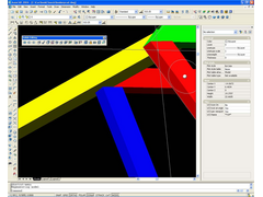
pic1: photo taken from the side.. as you can see Fu and LC are not very inline.
Image deleted by owner
Pic2: drawing of how the brackets would have to be placed to fit the wishbones and how they would be pointing a bit backwards.
Image deleted by owner
so i guess it really wouldnt matter as the wheels can be set straight using the track rod joints right? but it just does not look right
is there any way of fixing this so that i dont have to bend the brackets and make a dogs-dinner out of the build?
thanks!
Tom
|
|
|
|
|
Gunner1
|
| posted on 21/8/06 at 12:59 PM |
|
|
On our McSorley designed chassis, Zetec 7 and I have FU1 and Fu2 parallel.
Suggest you shorten up your front horizontle members to bring the front verticle member in and make them in line with each other.
Then your upper and lower control arms can be parallel and swing in the same arcs.
|
|
|
MikeR
|
| posted on 21/8/06 at 03:03 PM |
|
|
serious question, i can't figure out exactly what it would do to the suspension.
can anyone help?
|
|
|
Peteff
|
| posted on 21/8/06 at 03:43 PM |
|
|
Won't it give toe out in bump? Make the top rear brackets longer and space the bottom rear ones out with something to support them?
yours, Pete
I went into the RSPCA office the other day. It was so small you could hardly swing a cat in there.
|
|
|
ned
|
| posted on 21/8/06 at 04:57 PM |
|
|
for some reason i can't help thinking that in the pic the top engine bay rail should be almost 1/2" further towards the outside of the
chassis which might go some way to getting your tubes inline. best way to do it is to jig the brackets and then weld fu1/2 afterwards, the beauty of
hindsight! 
beware, I've got yellow skin
|
|
|
robertst
|
| posted on 21/8/06 at 04:58 PM |
|
|
quote:
Originally posted by Peteff
Won't it give toe out in bump? Make the top rear brackets longer and space the bottom rear ones out with something to support them?
hmm... it'll look funny though wont it?
the bottom wishbones are ok. they're straight. (EDIT: NOT!)
how about welding a chunk of RHS to the FUs so the bracket part sticks out parallel with the front? and reinforcing that with welded plates on top of
it to the chassis for extra peace of mind?
check the postit
(i love to draw ) )
Image deleted by owner
basically (to know where i tarted on) is it the front LALBLCLD part i did wrong with a combination of having the bottom Fs and top Js too much inside
bottom LD?
[Edited on 21/8/06 by robertst]
[Edited on 21/8/06 by robertst]
Tom
|
|
|
zetec7
|
| posted on 21/8/06 at 05:35 PM |
|
|
That would work too...but you'd better gusset the hell out of it for strength. My inclination is, go with Gunner1's suggestion.
Narrowing the front is going to be much stronger than lenthening the rear. And prettier, too!
|
|
|
kb58
|
| posted on 21/8/06 at 06:43 PM |
|
|
As weird as it looks, I think all it'll do is give caster.
[edit] oh wait... are those the lower a-arms? If so it'll still give you caster, but in the wrong direction...
[Edited on 8/21/06 by kb58]
Mid-engine Locost - http://www.midlana.com
And the book - http://www.lulu.com/shop/kurt-bilinski/midlana/paperback/product-21330662.html
Kimini - a tube-frame, carbon shell, Honda Prelude VTEC mid-engine Mini: http://www.kimini.com
And its book -
http://www.lulu.com/shop/kurt-bilinski/kimini-how-to-design-and-build-a-mid-engine-sports-car-from-scratch/paperback/product-4858803.html
|
|
|
Chippy
|
| posted on 21/8/06 at 07:20 PM |
|
|
What happens if set up as per drawing, you will get caster change in bump, I think that it would reduce as the suspension went upwards. Not a very
good idea. Regards Ray
|
|
|
paulf
|
| posted on 21/8/06 at 08:24 PM |
|
|
I would also check that the FU tube isnt going to come in the way of the steering column, it may do as the clearance isnt very great normally and with
the FU tube further in it could clash.
Paul.
|
|
|
Mansfield
|
| posted on 21/8/06 at 08:48 PM |
|
|
I was just about to start a thread around tis subject, but with respect to a +442 chassis.
I have modelled both book and +442 based on Mcsorely plans, and I cant get anywhere with the brackets lining up on either.
This looks a useful diagram however.
http://www.locostbuilders.co.uk/photos.php?action=showphoto&photo=front13-14.jpg
I will start my thread later as I dont want to hijack your thread Robertst.
|
|
|
omega 24 v6
|
| posted on 21/8/06 at 09:22 PM |
|
|
There is a definate problem with the 442 chassis brackets and the alignment of the FU tube on the steering downlink. See my photos showing how far out
the sizes are at this thread HERE'S THE PROBLEM
|
|
|
Mansfield
|
| posted on 21/8/06 at 10:15 PM |
|
|
In the next couple of days I will be asking opinions on my solution.
Looking at widening the bottom rails to get the lower rear mount properly on the bottom rail. Shorten LC and pull LA & LB together at the top.
Exact dimensions will depend on FU1 & FU2 position after moving bottom rails.
All will be revealed to me with a bit more cadding.
|
|
|
robertst
|
| posted on 22/8/06 at 12:29 AM |
|
|
quote:
Originally posted by zetec7
That would work too...but you'd better gusset the hell out of it for strength. My inclination is, go with Gunner1's suggestion.
Narrowing the front is going to be much stronger than lenthening the rear. And prettier, too!
you're right.. this solution, although a good one will look odd...
it is such a bugger though to grind down LC and LD and cut new ones to fit...
but wait! doing this i will seriously alter the track width of the car! the rear end will be far wider than the front and the car might end up looking
like a hot-rod... isnt the lotus 7 design supposed to have equal axle widths?
big question then is: if i do this, won't the front end be too small for a nosecone designed for the +4 chassis? the front end of the
chassis will be quite narrow and the nosecone might not have much resting space...
about the steering... i guess there's ways to overcome this... if i use a double UJed downlink i can basically route it whererever i want
really...
Tom
|
|
|
Mansfield
|
| posted on 22/8/06 at 07:28 PM |
|
|
I think you need to add four inches to the modified dimensions shown in the link to Leto's archive from my previous reply.
http://www.locostbuilders.co.uk/photos.php?action=showphoto&photo=front13-14.jpg
This would mean new LA/LB/LC but it should solve your problem. It should also mean 'book' wishbones can be used.
The drawings in Leto's archive have consistent suspension pivot points but he has corrected LA/LB/LC so you can use standard brackets to get to
those points. The FU positions pretty much fixed in the front elevation so I would leave them alone.
|
|
|
robertst
|
| posted on 22/8/06 at 09:42 PM |
|
|
ok, so should i follow the 14" modified bracket layout or the 13" one?
whats the 14" and 13".. surely it isnt wheel diameter?
and add 4" to what.... all measurements?
thanks
[Edited on 22/8/06 by robertst]
Tom
|
|
|
Mansfield
|
| posted on 22/8/06 at 10:10 PM |
|
|
The 14" high chassis at the top of the link has an extra 1" added to the height. Gives more engine/bonnet clearance and more room for
your knees.
The bottom left drawing shows the book set up, with the 22 radius circle indicating how far the bracket needs to be from LA, LB, FU1 & FU2. If
you look closely you will see a 'book' bracket (22mm from hole to base) would need to be 'cut into' the chassis members LA,
LB, FU1 & FU2 to give the correct overall geometry.
I think this error (especially with LA & LB sticking further out) shows what you have found in reality.
The +4 chassis just adds 4" to every member across the chassis, so to follow the solution suggested by Leto add 4" to the bottom right
drawing.
That said, something looks odd with the 612mm & 591mm dimension of Leto's front view. I dont know if these dimensions are possible.
I have been looking at +442 geometry so I cant give you dimensions tonight, but I will have a look tomorrow night to see what can be done.
[Edited on 22/8/06 by Mansfield]
|
|
|
Mansfield
|
| posted on 22/8/06 at 10:18 PM |
|
|
The more I look at the 'solution' the more wrong it looks - I will have a better look tomorrow.
|
|
|
Mansfield
|
| posted on 23/8/06 at 08:55 PM |
|
|
Leto's dimensions check out well. To make these work the top of the FU members have to sit inboard of the top rail by 11.5mm. This might be
useful to you as (Ned spotted this in his reply) the FU in your first picture sits inboard by a noticeable amount.
I cant quite work out where your differences have come from. According to the book geometry I think you would have to add packing to LA & LB to
get the wishbones working parallel to the chassis centreline. Have you got LC in at the correct length?
[Edited on 23/8/06 by Mansfield]
|
|
|
Mansfield
|
| posted on 23/8/06 at 08:57 PM |
|
|
I meant to add this picture to the above.
 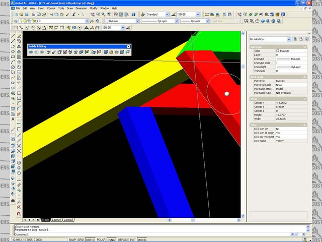
Rescued attachment Image11.jpg
|
|
|
robertst
|
| posted on 27/8/06 at 08:24 PM |
|
|
great help mansfield. thanks! so to get things clear, i have to adjust the lengths of LC and LD (horizontal ones) and basically move LA and LB
inwards until they are almost parallel with FUs with an offset of what you said: 11.5mm and that would be the chassis centreline?
Tom
|
|
|
Mansfield
|
| posted on 27/8/06 at 09:35 PM |
|
|
Letos drawing shows (bottom right) the dimensions required to give you correct wishbone bracket placement assuming you are using book sized brackets.
The book sized bracket is around 22mm from base of bracket to hole.
http://www.locostbuilders.co.uk/photos.php?action=showphoto&photo=front13-14.jpg
If you have cut LD to book+4 the that should need no mods. To me, the important dimensions are the overall sizes and how they are positioned about
the centreline of the chassis. Rather than pulling in the FUs by 11.5mm, I would try to ensure that the 591mm (+4, I will let you do the maths)
dimension is accurate and even about the centreline. Same with the dimension for LC (+4). This way, any inaccuracies in the position of your upper
and lower chassis rails will be accounted for.
Using Letos dimensions, you will be able to use book wishones and you will get a 4" wider track.
Still cant quite see why your front geometry is so far wrong though, I would check the front of your chassis as good as you can to see if you can find
the error.
David.
|
|
|
Mansfield
|
| posted on 28/8/06 at 08:45 AM |
|
|
I have posted a thread to see if anyone can confirm what I am saying is good advice or not.
http://locostbuilders.co.uk/viewthread.php?tid=50913
David.
|
|
|


.jpg)