grandad
|
| posted on 23/12/07 at 08:31 AM |

|
|
Chassis Plans
Hi Chaps
my current project is my first ad will be a good learning curve. i have the chris gibbs book and it has given me a good start.
the problem is i have been trying to Solid model the book chassis and the bits dont fit correctly. i use solidworks every day for work and know that
the problems are not in my CAD.
is there any where i can obtain chassis plans (including suspension) or should i just correct all the errors. i dont want to produce a car that i
cannot buy body parts for!!!
cheers phil
Merry Xmas one and all....
|
|
|
|
|
snapper
|
| posted on 23/12/07 at 08:45 AM |
|
|
If you go to the Haynes Roadster Forum, Chris and others have posted the corrections.
The link is currently down!
I eat to survive
I drink to forget
I breath to pi55 my ex wife off (and now my ex partner)
|
|
|
bonzoronnie
|
| posted on 23/12/07 at 09:13 AM |
|
|
Haynes roadster
Hi
The haynes Roadster site is down at the moment
I thought I had all the latest amendments on my PC as PDF files, i cant find them though 
I will look at my paper copies for any chassis amendments.
I dont think there are very many though.
My Book chassis is built. It came together well & as per book dimensions.  
Ronnie
[Edited on 23/12/07 by bonzoronnie]
|
|
|
scotty g
|
| posted on 23/12/07 at 09:51 AM |
|
|
hi phil, where abouts in Kent are you matey?
|
|
|
delboy
|
| posted on 23/12/07 at 12:48 PM |
|
|
phil,
This is the list of the book amendments, I copied it and printed it of so as it was handy to access when in the workshop, I hope it helps.
Book Amendments
1. Page 30/31 Add 1mm steel sheet, 5mm and 10mm plate along with 65mm long, 5 inch
external diameter pipe. Also add 28 mm external x 22mm internal tube for the pedal pivots.
2. Page 37 Text
Note that U3 and U6 are aligned square with either end of tube BR10
Should read
Note that U3 and U6 are aligned with the outside of tubes BR3 and BR4 respectively
This is why the outside lip of the upright section of the pedal box is angled at 20 degrees.
3. Page 51 Figure 4.30 The 90mm vertical dimension should be from the top of tube BR1 not
the bottom
4. Page 57 Figure 5.3 Two 50mm dimensions are incorrect, they should be 47mm.
5. Page 57 Figure 5.4 The support frame for the front lower wishbone support frame doesnt
have the vertical height dimensions.
The lower end should be 10mm high and the upper end 18.5mm
6. Page 62 Figure 5.11 shows an angle of 78 degrees - this is incorrect it should be 82
degrees to agree with the complimentary angle of 98 degrees in figure 5.12.
7. Page 63 Text
The 8mm and 2mm spacers should be tacked on and the 25 x 3mm plates are positioned as
shown in figure 5.11
Should read
The 8mm and 2mm spacers should be tacked on and the 25 x 6mm plates are positioned as
shown in figure 5.11
8. Rear driveshafts
It might seem obvious that you should use the Sierra driveshafts, but I forgot to mention in the
book that they should be shortened by 10mm each side, If you are going to use the rear
wishbones as shown in the book.
It might be easier to widen the track of the car slightly by making each upper and lower rear
wishbone 10mm longer, as shown in the attached PDF drawings, enabling you to use
standard driveshafts.
9. Page 65 Figure 5.15, the space between the side of the jig and the 25 x 25mm-tube
should be 73.5mm rather than 76mm. 206 + 73.5 + 73.5 =353.
10. Damper lengths
In the book we suggest 13in open, 9in closed dampers. Doing a little work on the suspension
geometry, Ive discovered that a one-inch extension on the top of the dampers would allow
more droop movement, without affecting the bump. This will give better performance on
bumpy surfaces (read every road in Britain!).
The dampers would still be 13in open, 9in closed, but with a one-inch solid extension fitted to
the top. Both Dampertech and Protech produce this type of damper.
11. Page 70 Figure 5.24 shows plate RU7 as being 3mm thick its actually 10mm thick as
shown on page 179.
12. Page 70 Figure 5.24 NOTE
Rotate RU7 (add and RU5) through 180 degrees.
13. Page 71 Figure 5.25 12mm internal diameter tube, 50mm long -
.. should read
12mm internal diameter tube, 44mm long -
14. Page 72 Text. (2nd Paragraph)
The main body of the upright is made from a 70mm Long section of 5 Internal pipe ....
Should read
The main body of the upright is made from a 65mm Long section of 5 External pipe ....
15. Page 72 Figure 5.29 has the notation reversed, the holes should be aligned horizontally
for drum brakes. Add 94mm hole centre dimension to left hand pair of holes on the left hand
diagram which is actually for DISK brakes and Add 94mm hole centre dimension to top pair of
holes on the right hand diagram which is actually for DRUM brakes.
16. Page 73 Text. (Last paragraph).
The lower wishbones need to be installed with cross brace angled from outside front to
inside rear.
Should read
The lower wishbones need to be installed with cross brace angled from outside rear to inside
front
17. Page 99 Figure 8.16 TR8 has been written in twice, should be TR8 and TR9 (TR9 is the
uppermost)
18. Page 100 Figure 8.18. WS6 tag is omitted, its the upright plate tagged 25 x 3mm steel
strip, bottom left.
19. Page 108 Figure 9.2 The hole in the brake pedal is shown as 8mm, it should be 6.5mm.
20. Page 123 Under Section 5 Seat Belts, the first sentence reads In his book it should of
course read In This book
21. Page 124. Section 9. (last sentence) Text
The minimum separation (to the inside of the lenses) is 500mm
Should read
The outside edges of the front indicator lenses have to be 400mm, or less, from the outside
of the car, (outer edge of the front wings).
22. Page 184 both drawings, the dimensions to the bend lines dont match the inside
dimensions of the brackets.
Suspension brackets, two dimensions at 23mm adding up to 44mm, should be two at 22mm =
44mm.
Shock absorber brackets two dimensions at 18mm adding up to 34mm, should be two at
17mm = 34mm.
|
|
|
Echidna
|
| posted on 23/12/07 at 12:52 PM |
|
|
Anyone has the LHD plans from the forum?
|
NOTE:This user is registered as a LocostBuilders trader and may offer commercial services to other users
|
grandad
|
| posted on 23/12/07 at 06:38 PM |
|
|
Hi Scotty G
i am living in Maidstone,
Cheers
Phil
|
|
|
chrisg
|
| posted on 23/12/07 at 08:48 PM |
|
|
quote:
Originally posted by grandad
Hi Chaps
my current project is my first ad will be a good learning curve. i have the chris gibbs book and it has given me a good start.
the problem is i have been trying to Solid model the book chassis and the bits dont fit correctly. i use solidworks every day for work and know that
the problems are not in my CAD.
is there any where i can obtain chassis plans (including suspension) or should i just correct all the errors. i dont want to produce a car that i
cannot buy body parts for!!!
cheers phil
Merry Xmas one and all....
Hi Phil,
You've come across the old "accuracy conundrum"
I've drawn the chassis in Solidworks, Autocad and Sketchup.
The problem is that the computer program is FAR more accurate than someone making a chassis.
Anyone who can work in steel to an accuracy of plus or minus 1mm is doing well, but some dimensions and angles of the chassis are the like of
456.887676545.
Now we could use the precise dimension, but there doesn't seem much point going to that level of accuracy when it couldn't be replicated
in the real world.
To be honest half a millimeter here and there won't make much difference. The best way to look at it is to get everything as accurate as
possible but finish the tubes with a file to ensure that the overall dimensions are correct. The jigs for the suspension pickups are very important
and this is one area where precision is desirable and possible due to the infinate asdjustment available.
You'll find it very difficult to draw in a program as accurate as Solidworks without access to the precise dimensions.
There have been some changes to the errors file and I've included the most recent version below.
"Build your own Sports Car on a Budget.
Book Amendments
1. Page 30/31 Add 1mm steel sheet, 5mm and 10mm plate along with 65mm long, 5 inch external diameter pipe. Also add 28 mm external x 22mm internal
tube for the pedal pivots.
2. Page 37 Text
Note that U3 and U6 are aligned square with either end of tube BR10
Should read
Note that U3 and U6 are aligned with the outside of tubes BR3 and BR4 respectively
This is why the outside lip of the upright section of the pedal box is angled at 20 degrees.
2a Page 39 Text
U1 and U2 should be fixed next, noting that they are placed square to rail BR7 at the bottom. The top rear corner is aligned with the outside of the
rails TR1/TR2.
Should read
U1 and U2 should be fixed next, noting that they are placed square to rail BR7 at the bottom. The top front corner is aligned with the outside of the
rails TR1/TR2.
2b Page 47 Text CP13 sits between the TT rails, 12mm from the bottom and 145mm behind TT8
Should read
CP13 sits between the TT rails, 12mm from the bottom and 125mm behind TT8
3. Page 51 Figure 4.30 The 90mm vertical dimension should be from the top of tube BR1 not the bottom
4. Page 57 Figure 5.3 Two 50mm dimensions are incorrect, they should be 47mm.
5. Page 57 Figure 5.4 The support frame for the front lower wishbone support frame doesnt have the vertical height dimensions.
The lower end should be 10mm high and the upper end 18.5mm
6. Page 62 Figure 5.11 shows an angle of 78 degrees - this is incorrect it should be 82 degrees to agree with the complimentary angle of 98 degrees
in figure 5.12.
7. Page 63 Text
The 8mm and 2mm spacers should be tacked on and the 25 x 3mm plates are positioned as shown in figure 5.11
Should read
The 8mm and 2mm spacers should be tacked on and the 25 x 6mm plates are positioned as shown in figure 5.11
8. Rear driveshafts
It might seem obvious that you should use the Sierra driveshafts, but I forgot to mention in the book that they should be shortened by 10mm each side,
If you are going to use the rear wishbones as shown in the book.
It might be easier to widen the track of the car slightly by making each upper and lower rear wishbone 10mm longer, as shown in the attached PDF
drawings, enabling you to use standard driveshafts.
9. Page 65 Figure 5.15, the space between the side of the jig and the 25 x 25mm-tube should be 73.5mm rather than 76mm. 206 + 73.5 + 73.5 =353.
10. Damper lengths
In the book we suggest 13in open, 9in closed dampers. Doing a little work on the suspension geometry, Ive discovered that a one-inch extension on the
top of the dampers would allow more droop movement, without affecting the bump. This will give better performance on bumpy surfaces (read every
road in Britain!).
The dampers would still be 13in open, 9in closed, but with a one-inch solid extension fitted to the top. Both Dampertech and Protech produce this type
of damper.
11. Page 70 Figure 5.24 shows plate RU7 as being 3mm thick its actually 10mm thick as shown on page 179.
12. Page 70 Figure 5.24 NOTE
Rotate RU7 (add and RU5) through 180 degrees.
13. Page 71 Figure 5.25 12mm internal diameter tube, 50mm long -
.. should read 12mm internal diameter tube, 44mm long -
14. Page 72 Text. (2nd Paragraph)
The main body of the upright is made from a 70mm Long section of 5 Internal pipe ....
Should read
The main body of the upright is made from a 65mm Long section of 5 External pipe ....
15. Page 72 Figure 5.29 has the notation reversed, the holes should be aligned horizontally for drum brakes. Add 94mm hole centre dimension to left
hand pair of holes on the left hand diagram which is actually for DISK brakes and Add 94mm hole centre dimension to top pair of holes on the right
hand diagram which is actually for DRUM brakes.
16. Page 73 Text. (Last paragraph).
The lower wishbones need to be installed with cross brace angled from outside front to inside rear.
Should read
The lower wishbones need to be installed with cross brace angled from outside rear to inside front
17. Page 99 Figure 8.16 TR8 has been written in twice, should be TR8 and TR9 (TR9 is the uppermost)
18. Page 100 Figure 8.18. WS6 tag is omitted, its the upright plate tagged 25 x 3mm steel strip, bottom left.
19. Page 108 Figure 9.2 The hole in the brake pedal is shown as 8mm, it should be 6.5mm.
20. Page 123 Under Section 5 Seat Belts, the first sentence reads In his book it should of course read In This book
21. Page 124. Section 9. (last sentence) Text
The minimum separation (to the inside of the lenses) is 500mm
Should read
The outside edges of the front indicator lenses have to be 400mm, or less, from the outside of the car, (outer edge of the front wings)."
I don't know what's up with the forum, I'll inform Haynes.
cheers
Chris
Note to all: I really don't know when to leave well alone. I tried to get clever with the mods, then when they gave me a lifeline to see the
error of my ways, I tried to incite more trouble via u2u. So now I'm banned, never to return again. They should have done it years ago!
|
|
|
Echidna
|
| posted on 23/12/07 at 10:14 PM |
|
|
Chris, please post the drawings for the LHD version. Thanks!
|
NOTE:This user is registered as a LocostBuilders trader and may offer commercial services to other users
|
Beardy_John
|
| posted on 25/12/07 at 08:59 AM |
|
|
In the admendments above, ChrisG mentions that to use the standard driveshafts (i.e. not cut 20mm off each) the wishbones could be made longer by the
same amount.
Would you get the same result by making the chassis 40mm wider overall?? Or would it cock up of the wishbone geometry??
Cheers & a Merry Christmas to all !!! 
|
|
|
kb58
|
| posted on 25/12/07 at 04:40 PM |
|
|
It'll change the RC location slightly. Whether this is a good thing or not depends...
Mid-engine Locost - http://www.midlana.com
And the book - http://www.lulu.com/shop/kurt-bilinski/midlana/paperback/product-21330662.html
Kimini - a tube-frame, carbon shell, Honda Prelude VTEC mid-engine Mini: http://www.kimini.com
And its book -
http://www.lulu.com/shop/kurt-bilinski/kimini-how-to-design-and-build-a-mid-engine-sports-car-from-scratch/paperback/product-4858803.html
|
|
|
Beardy_John
|
| posted on 25/12/07 at 04:44 PM |
|
|
How do you calculate the RC so I can see what differecne it makes?? Any ideas??
|
|
|
Echidna
|
| posted on 25/12/07 at 05:51 PM |
|
|
quote:
Originally posted by kb58
It'll change the RC location slightly. Whether this is a good thing or not depends...
Hmmm....
I think that the RC will be the same, as long as the wishbone angles remain the same and the chassis centerline is also the same.
If, on the other hand, the chassis will be widened and the wishbone chassis pickups remain he same, then the RC will certainly change. I don't
think this would be a good idea though.
[Edited on 25/12/07 by Echidna]
|
NOTE:This user is registered as a LocostBuilders trader and may offer commercial services to other users
|
D Beddows
|
| posted on 26/12/07 at 12:27 AM |
|
|
quote:
I think that the RC will be the same, as long as the wishbone angles remain the same and the chassis centerline is also the same.
No, you're changing the geometry so it wont if you think about it because your theoretical roll centre isn't static BUT (unless your sole
suspension design reference is Alan Staniforth....) 'roll centres' are far from the be all and end all of suspension design that a lot of
people think they are.......in fact, if you really think about it what does a roll centre actually tell you? Controlling the angle of the wheel in
bump and rebound is vital as is eliminating as much bump steer as you can and self centering is waay more important for a car that
'feels' good to drive than a lot of people on here tend to think. Non of that has anything to do with roll centres though......
Or of course you can decide that all suspension theory is b*llocks and build you own F1 car
lol 
[Edited on 26/12/07 by D Beddows]
|
|
|
Echidna
|
| posted on 26/12/07 at 09:50 AM |
|
|
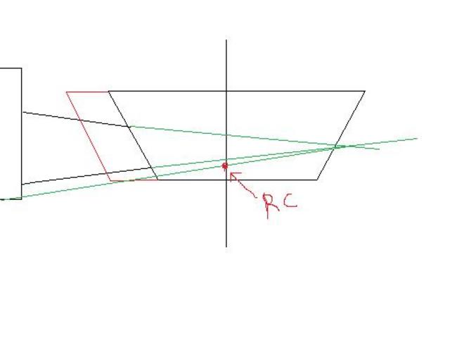
If the angles of the wishbones (you must change the wishbone chassis pickup points of course) and the chassis centerline remain the same then
the static roll center will remain the same. Just have a look at the drawing.
The red lines represent the widened chassis and you can see that in both cases (wide and narrow chassis) the static roll center is at the same
point.
You are right that the dynamic roll center will change as now the rotating points of the wishbones are different.
[Edited on 26/12/07 by Echidna]
Rescued attachment roll center.jpg
|
NOTE:This user is registered as a LocostBuilders trader and may offer commercial services to other users
|
Beardy_John
|
| posted on 26/12/07 at 10:05 AM |
|
|
so if i follow this right,
If i keep the wishbones at the same angle, and make the chassis wider, the point were all the lines cross will remain the same but move to the left
making roll centre higher reletive to the ground.
To keep an identical (or better) roll centre, i would need to reposition the wishbone brackets. Correct?
|
|
|
Echidna
|
| posted on 26/12/07 at 10:25 AM |
|
|
Your static roll center will be higher relative to the ground. If you reposition the wishbone brackets, you may achieve the same static RC but
you won't be able to achieve the same dynamic RC, just because your new shortened wishbones will follow different arcs during suspension
movement.
If your RC is higher, the result will be that you will have a greater percentage of the forces going through the joints and less percentage through
the dampers-springs-arbs. You will have greater roll stiffness too. Greater roll stiffnes means that you will have higher load tranfer to this
axle.
[Edited on 26/12/07 by Echidna]
|
NOTE:This user is registered as a LocostBuilders trader and may offer commercial services to other users
|
Syd Bridge
|
| posted on 26/12/07 at 11:42 AM |
|
|
Roll centres.
Oh dear dear.
Cheers,
Syd.
|
|
|
Alan B
|
| posted on 26/12/07 at 12:44 PM |
|
|
I would have thought by widenening the whole chassis roll centres would be least of you problems.....floor panels, bodywork, crosstubes etc.....lot of
work..
|
|
|
Beardy_John
|
| posted on 26/12/07 at 05:39 PM |
|
|
Not too bothered about bodywork etc, as i will make all that anyway and i am thinking about desining something a bit different anyway. All i wanted to
know was if i did make it a bit bigger would it drive like a bag of (xmas) socks!
I will keep the wishbones the same book length, just make the rear end of the chassis wider. as ever, your input and advice has been most useful.
Thanks all
|
|
|