phelpsa
|
 posted on 7/12/03 at 02:51 PM posted on 7/12/03 at 02:51 PM |

|
|
Lightening Chassis
What ways are there of lightening an already built chassis without losing any of the stiffness. I am using a bike engine(GSXR1100) to keep weight down
and it is not going on the road, no need for lights or anything. I am also using IRS.
Adam
|
|
|
|
|
kingr
|
| posted on 7/12/03 at 03:51 PM |
|
|
Without wishing to sound too patronising, if you have to ask, the chances are you probably shouldn't try. Go for weight savings elsewhere -
wheels and tyres will make a big difference, you'd be best to pretty much leave the chassis alone.
Search for posts by cymtriks, he's done analysis on the chassis and given recomendations for how you can make the chassis stiffer and save a
little weight.
Kingr
|
|
|
Liam
|
| posted on 7/12/03 at 05:07 PM |
|
|
If you're after all out track performance, you'd do well to actually add to the chassis to make it significantly stiffer. A
standard locost engine bay/front end is fairly wobbly, and most manafacturer IRS implementations I've seen lack stiffness in the quest for ease
of manafacture and practicallity. Short of a complete from-scratch rebuild with thinner guage tubing and a less compromised design geared soley to a
bike-engined track-only car, the chassis isn't the place to save weight.
Much better, as Kingo says, to loose weight where it matters (unsprung) with light uprights and hubs, nice Willwood billet calipers instead of the
Ford beasts, some nice light wheels (mmmmm OZ Superleggera), and them swanky rediculously light Avon tyres Cateringvans use.
You dont need heavy seats, any interior trim, a full width dashboard, reverse, etc etc. Oh and go on a diet 
Liam
|
|
|
Liam
|
| posted on 7/12/03 at 05:25 PM |
|
|
Woah!
Just noticed in another thread you have a 'Cosworth' diff. If its a RWD cossie diff then its a 7.5" fat-shafted chubba. Flog that
for loads of money and get a 7" lsd and normal sized shafts from an XR4x4 or 4x4 cossie. With a bike engine you certainly dont need a hefty RWD
cossie back end.
Kilograms!
Liam
|
|
|
phelpsa
|
| posted on 7/12/03 at 07:56 PM |
|
|
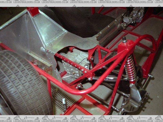
How do I know if it is 7.5 from a RWD. I did not buy it to go with the car, it all came in a package. I also have 4-pot calipers, I do not know who
they came from. I think I will need them as I am going to hillclimb.
Adam
P.S I have attached a picture showing the diff & rear end.
 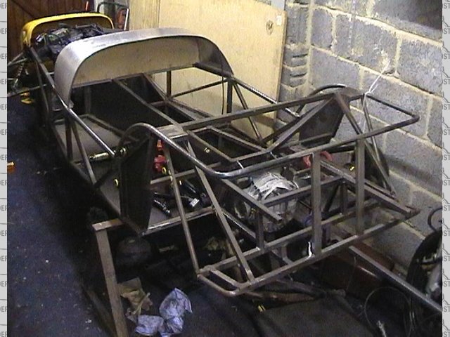
Rescued attachment locost4.jpg
|
|
|
Liam
|
| posted on 7/12/03 at 08:28 PM |
|
|
I believe the quick way is to measure accross the top diff mount. It will be 7" or 7.5" which is a handy coincidence as the dimension
really refers to the crown wheel diameter. The 7.5" has a beefier case and beefier internals to cope with monster torque and is a favourite of
V8 Dax Rush boys and the like. RWD cossies also have thicker heavier driveshafts.
What kind of chassis is that by the way? Tiger Avon? Stuart Taylor? Home built?
LIam
|
|
|
MikeR
|
| posted on 7/12/03 at 08:34 PM |
|
|
Looks like a Triton chassis to me - I saw some of hte first ones being built and the bit where they take the rear hoop and make it into the rear wheel
arch is rather nice.
|
|
|
phelpsa
|
| posted on 7/12/03 at 09:19 PM |
|
|
It is a homebuilt chassis which I have bought from a guy who found it difficult to get hold of an escort as a donor car. He got some stuart taylor
wishbones and the back end off a RWD cossie an started to design his own rear end (which isn't quite right) to IRS.
Adam
|
|
|
pbura
|
| posted on 8/12/03 at 03:48 AM |
|
|
To lighten the chassis a lot would require re-doing quite a lot of it, like using ally for the floor and transmission tunnel. It's hard to tell
from the pic, but are the tranny tunnel and diagonal braces done in 3/4" as they should be?
Yes, the rear end needs some work. I'm throwing in a pic of a Donkeyvoort for comparison:
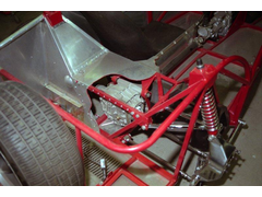 
IRS rear
[Edited on 8/12/03 by pbura]
Pete
|
|
|
fester
|
| posted on 8/12/03 at 07:04 PM |
|
|
Hi Adam;
Just out of interest,what model gsxr motor do you have? Is it oil/air cooled as in j,k or l or is it a w prefix as in water cooling?
Just asking as I have a gxsr1100k which I considered for my build but discounted due to the need for a much larger oil cooler because the motor
would effectively be out of the air blast.
Cheers Fest
|
|
|
cymtriks
|
| posted on 8/12/03 at 10:38 PM |
|
|
Chassis stiffness
This is how to stiffen and lighten the chassis. This is all based on the results of a finite element analysis that I did of the Lowcost chassis.
This is our starting point.
Chassis by the book with 16 gauge sheet steel panels
Stiffness is 1180 ftlbs per degree of twist
The weight is 181 lbs.
With a welded on dashboard structure and considering some of the possible variations in the book the stiffness could be about 1400 ftlbs per degree of
twist.
The simplest option to increase chassis stiffness, which is in the book, is to weld in a steel panel between tubes E and LD. If this is done then we
have the following.
Chassis by the book, including optional front panel, with 16 gauge sheet steel panels
Stiffness is 1301 ftlbs per degree of twist
The weight is 184 lbs.
With a welded on dashboard structure and considering some of the possible variations in the book the stiffness could be about 1500 ftlbs per degree of
twist.
This is how to up rate the Lowcost chassis from the initial starting point given by the book chassis.
All of the tubes in the original design remain as in the book. The extra tubes are assumed to be 1 inch square with 16 gauge wall thickness. All of
the steel panels, except for the seat belt mount reinforcements and rear suspension mount reinforcements, are 18 gauge. This change in the panel
thickness gives a worthwhile weight saving.
Form a V joining the centre of tube LC to the ends of tube LD. This triangulates the front with the tubes running immediately behind the radiator. The
reduction in airflow will be minimal. If radiator, fan or water pipe clearance is a problem then a diagonal or X brace across the chassis in this
position may be used. Alternatively a similar modification connecting the ends of tubes FU1 and FU2 may be used but may cause clearance problems with
the front of some engine ancillaries. A front V brace adds two tubes to the chassis.
Form two diagonal braces, one on each side of the chassis, between the tops of tubes LA and LB and the bottoms of tubes FU1 and FU2. This carries the
triangulation of the chassis sides right to the front of the chassis and crosses the rectangular hole in each side of the chassis roughly defined by
the top and bottom wishbone mounting points. Check that there is room for the steering rack. The braces add two tubes to the chassis.
Some Lowcost builders have reported that the floor is prone to flexing when thin gauge steel is used. Floor reinforcing tubes, running parallel to B2
and just in front of or under the front of the seats may be welded in, one on each side of the car. This adds two tubes to the chassis.
Weld in a panel across the bottom of the chassis between tubes E and LD. The book gives this as optional. The alloy panel referred to in the book
contributes little to the chassis.
The next step is to box in the transmission tunnel from tube O3 to tube P. This makes the transmission tunnel into a welded 18 gauge steel tube
enclosed on the sides, top and bottom. A hole for the gearlever will be required. A hole for the handbrake will also be required unless you decide to
mount the handbrake under the dashboard as on the Caterham Seven
If you intend to establish the length of the propshaft as described in the book then you will have to leave the tunnel unfinished until after the prop
dimension is taken. For final assembly it should be possible to feed the prop spline onto the gearbox spline as the area beneath the gearbox, in front
of tube B2, is not panelled. The propshaft may need to be fixed to the diff during final assembly as the rear propshaft flange may be inaccessible in
the finished boxed in tunnel.
The ¾ inch tubes forming the frame of the transmission tunnel do nothing if this modification is done and we can therefore take an opportunity to
reduce weight. Delete tubes c, d, g, h, i, j, the two rear k tubes and the tube which connects the tops of the two rear k tubes. A single arch over
tube B2 may be required to give local reinforcement to support the handbrake or gearshift mechanisms hence the retention of the front k tubes and the
tube that connects their tops. Check a Caterham chassis if you find it hard to believe that these tubes may be removed, it has a very light structure
in this region indeed. This step removes a total of nine tubes from the chassis.
The result is a chassis with a modified front, 18 gauge sheet steel panels and a boxed in tunnel with no internal ¾ inch tubes except for a front hoop
and the floor braces.
The stiffness is now 2541 ftlbs per degree of twist and the weight is 171 lbs
The weight is lower, the stiffness much higher and the number of tubes is reduced by three compared to the basic chassis built to the book. This shows
that extra stiffness need not mean extra weight or complication.
If a Satchel link is used to locate a live axle or Deon axle or if an independent double wishbone suspension is used then the tubes around the back of
the transmission tunnel will need to be stronger than ¾ inch and should be 1 inch square as a minimum.
The best stiffness is achieved with an additional modification to the engine bay. Delete tube R and replace it with two Y braces. This has the
advantage over using two R tubes, on both sides of the engine bay, of providing more space to accommodate bigger engines. The normal way of
accommodating a large engine is to use one or two short engine bay diagonals that do not extend to the front of the engine bay but instead join the
tubes on the sides of the engine bay. The double Y brace arrangement is show in my picture in the pictures section and is superior to any arrangement
using one or two short diagonals though it is slightly more complex.
The double Y braced chassis, with all the extra diagonals, a modified transmission tunnel and reduced panel thickness has a stiffness of 2683 ftlbs
per degree of twist for a weight of 174 lbs. This requires only two extra tubes compared to the book chassis and is seven pounds lighter.
I hope that helps but it looks as if the chassis shown is already finished and most of my mods will be hard to make without a big carve up.
Regards
Chris
|
|
|
merkurman
|
| posted on 8/12/03 at 11:30 PM |
|
|
I am working a a rear IRS setup using GM uprights (midsized car) which are everyehwere her eand cast AL. the strut bolts on using two bolts which
makes adding a bracket for a upper wishbone easy. I am thinking of rocker arm suspension with the coilovers over the diff so that all teh loading is
on the center of the car and down through the tranny tunnel. going to be bike powered but haven't picked any one yet. using a US ford diff
sinc ethey are AL and dirt cheap here and have tons of gearing and lsd choices for cheap. I am looking at a chromemoly frame sinc eI have access to
it here at uni.
nick
1962 fairlane with a 200" six and T5 5spd, shaved trim air ride, t3/t4 turbo and soon to be EFI
-- looking to put a offy tripower intake on soon
|
|
|
blueshift
|
| posted on 9/12/03 at 02:15 AM |
|
|
Nice one cymtriks..
quote:
Originally posted by cymtriks
If a Satchel link is used to locate a live axle or Deon axle or if an independent double wishbone suspension is used then the tubes around the back of
the transmission tunnel will need to be stronger than ¾ inch and should be 1 inch square as a minimum.
Does this apply if you're doing dedion with a panhard rod, but need the back of the tunnel area to support a sierra diff?
|
|
|