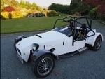
the moa 2
|
| posted on 5/5/09 at 12:19 PM |

|
|
ZX12R wiring
I have been having problems with a fuse that keeps popping.
Can someone with a ZX12-R set up please check something out as i think it may be a simple error made on our behalf.
Please can you check what amp fuse you have feeding the Main White unswitched power line.
We have i think got a 15amp fuse when i think it should be 30amp.
|
|
|
|
|
rb968
|
| posted on 5/5/09 at 12:34 PM |
|
|
Well I have a ZX9 engine and thats defo a 30amp main fuse if that helps. Sorry can't be of more use.
Rich
|
|
|
eznfrank
|
| posted on 5/5/09 at 12:35 PM |
|
|
I'm convinced it's a 30 but I'll check when I get home unless anyone else gets there first
|
|
|
the moa 2
|
| posted on 5/5/09 at 12:39 PM |
|
|
oh god i have been such an idiot car has been off the road for a year because of this every time i looked at the wiring i couldnt find any faults.
I do hope this is the problem its gonna be such an easy fix.
|
|
|
eccsmk
|
| posted on 5/5/09 at 01:01 PM |
|
|
30 amp here 
|
|
|
the moa 2
|
| posted on 9/5/09 at 09:04 AM |
|
|
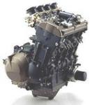
Hi guys i am pretty convinced that all this time i have just had the wrong fuse but i have digged out some old info from the web from which i used to
sort most of my wiring out.
Within it he advises to feed the white line via a 15 amp fuse. Would his loom maybe from a different year zx12-r or what im not sure.
See below clip from the bike-engineed cars yahoo groups.
On further inspection the link between cyls 2-3 goes to some sort of
emission valve on the top of the engine which is missing on mine. A
picture is on page 1-38 if you have the same CD manual as me.
AS for the wiring assuming you have the same model as me (The ECU plugs
are 2x34 pins). Usual disclaimer... check check and recheck your own
circuit diagram.... it's your responsibility not mine. This is what I
THINK I did :-)
Look at the circuit diagram on 2-22
1. The resistor = 100ohms in the Grey wire that runs from 10 amp ign
switched feed to pin 39 on ECU. This line gets it's power from the white
line on the bike via the ign switch (item 17) . I power this line from my
dashboard ign switch.
2. Defeating the interlocks
Earth pin 20 - Light Green..... This knocks out the need for the side
standswitch, and the clutch lever interlock, and helps you remove the
fusebox.
3. Power feeds into loom.
The white wire is unswitched main power feed it is feed via a 15 amp fuse
in the battery box (item 31) . It feeds the ignition switch where it
becomes switched and Brown and returns to the main fuse box (22 & 23),
where it passes through a 10amp fuse and becomes Brown\White. Again I
power the Brown line via the dash board ign switch and a 10 amp fuse.
I have connected brown - brown white outside the main fuse box as my 10amp
fuse is elsewhere. With the interlocks defeated this meant that I could
ditch the fuse box.
The Brown line also feeds the ECU relay energising coil
The white Line is the main loom feed via the main 15amp fuse in the
battery box in the bike. I simply run it from an unswitched feed and
15amp fuse on my dash.
4. Kill switch connections (19)
The kill switch has a Brown White (10 amp ign switched) feed from the
fuse box
box, this returns as a red line which feeds the stick coils, the starter
button, pin 32 on the ECU (detect engine stop switch off). This red line
also feeds the ECU relay energising coil. It needs to be held at 12v if
the engine is to run.
I directly linked this red line to my brown\white 10amp protected ign
switched feed to remove the kill switch.
5.Connect the Black\Red line that runs from the start button to ECU pin 28
to the switched side of your starter button. It also provides power via
the main starter relay in the fuse box to run the starter motor. The
starter relay in the fusebox (24) is energised by the interlocks system
so this can now be ignored. Therefore connect Black\Red line from your
starter button directly to the yellow red line that feeds the relay.
6. I also did things like connect the FI indicator (item 21 and ECU pin
33) to warning LED on my Dashboard, and brought the ECU test switch (item
35, pins 54 & 61) to a push button on my dash.
I hope this all helps
Adrian
|
|
|