b14wrc
|
| posted on 7/4/13 at 03:52 PM |

|
|
Hi.
Yes the wheel clears the trailing arm and the bottom arms are spaced off the centre line exactly the same front/rear pick ups.
Once I have the bushes I will check the camber change through travel and see what steering changes might happen, to be honest I can't see how
that could happen as the bottom mounts are fixed in one plane of movement, ie the in and out, for rear steer I'd need toe alterations which from
my current trails "seems" ok.... May be wrong mind.
BT, I know what your on about with the 'flop' I will also check as was a concern, I may end up welding the camber control arm directly to
that ball joint plate. Will see how it all works once bolted and bushed.
Regards, Rob
PS, yes, a lot of effort so far has gone into this.
 possibly an understatement! possibly an understatement!
20vt powered rear engined locost
|
|
|
|
|
b14wrc
|
| posted on 20/4/13 at 04:14 PM |
|
|
I've made some temporary bushes now to get the suspension working, so far, seems good.
These bushes are too hard and brittle, going to have a better mould machined at work and cast some PU rubber ones.
Top arm is still being thought about with comments made earlier. I'm thinking simplifying it to a single A arm mounted with two rose joints.
Rob
20vt powered rear engined locost
|
|
|
b14wrc
|
| posted on 3/6/13 at 10:17 PM |
|
|
It's been a while chaps, finally got in the garage on Saturday!
Does this look a better design?
Still a bit to do, but it's coming along....
Rob
20vt powered rear engined locost
|
|
|
the1theycallthe1
|
| posted on 4/6/13 at 01:39 PM |
|
|
Looks great.
|
|
|
b14wrc
|
| posted on 27/7/13 at 07:55 PM |
|
|
Hi all,
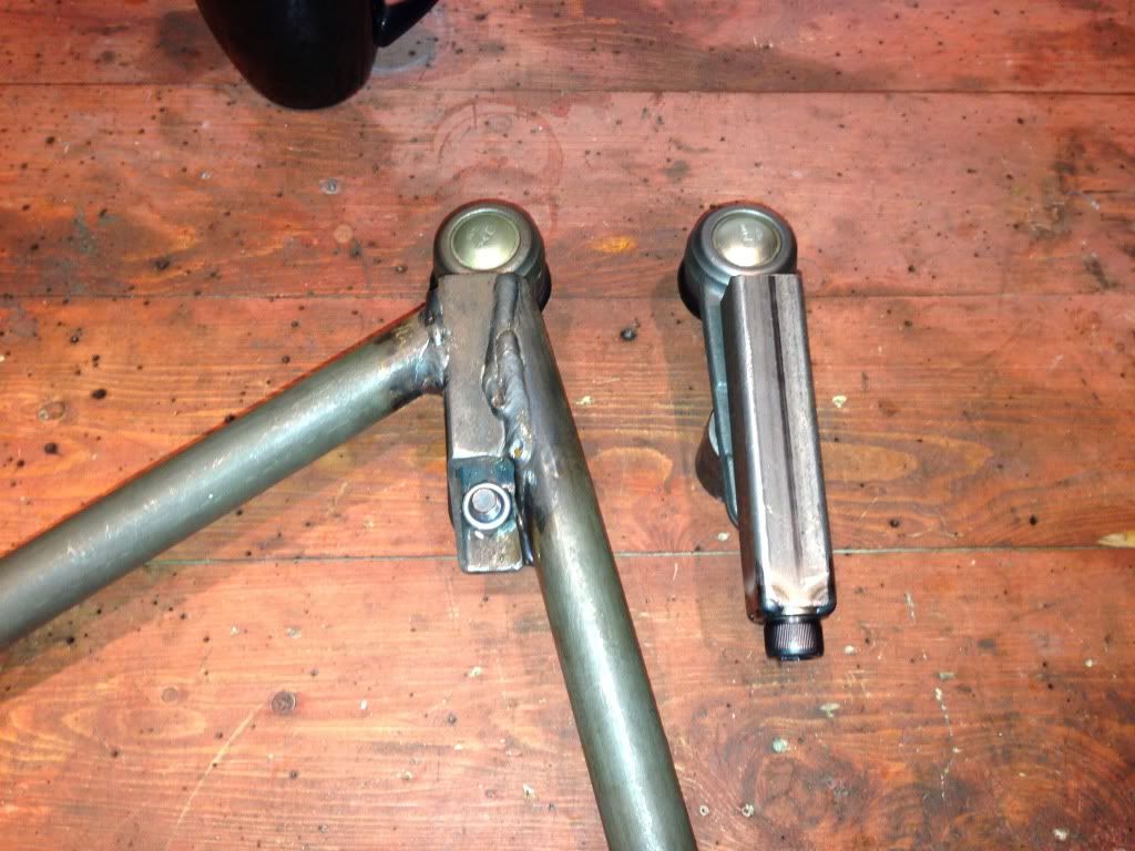
Had a bit on recently and only got back to locost last week. So, I wasn't happy with the mk 2 upper rear arm, basically it didn't work.
Camber control was difficult to adjust and the front pick up is not aligned with rear, so that needs changing.
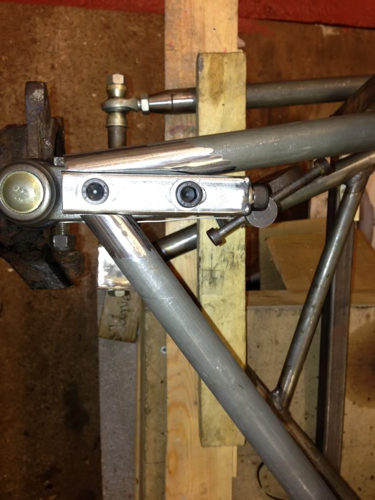
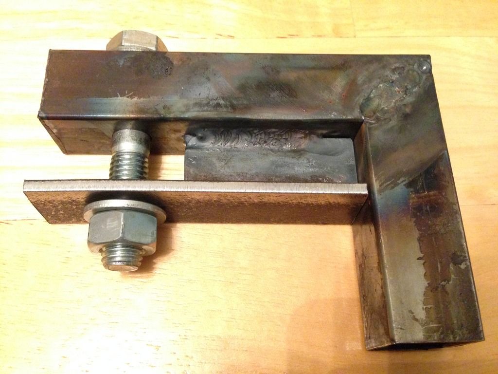
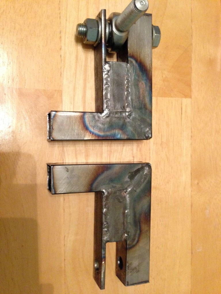
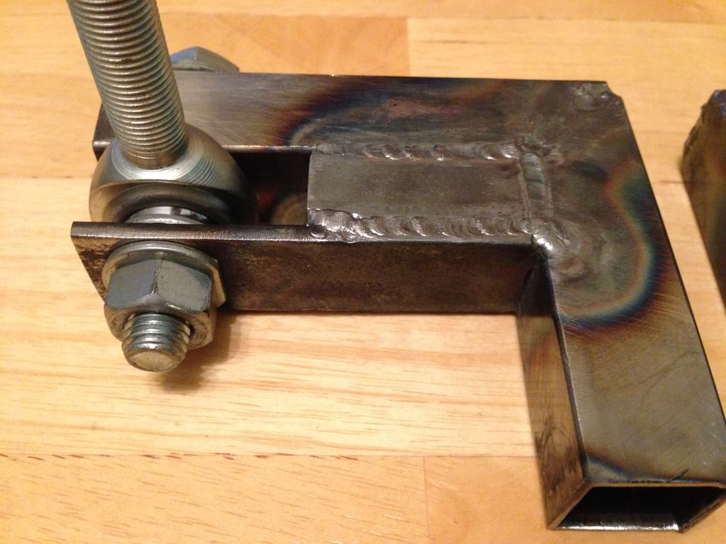
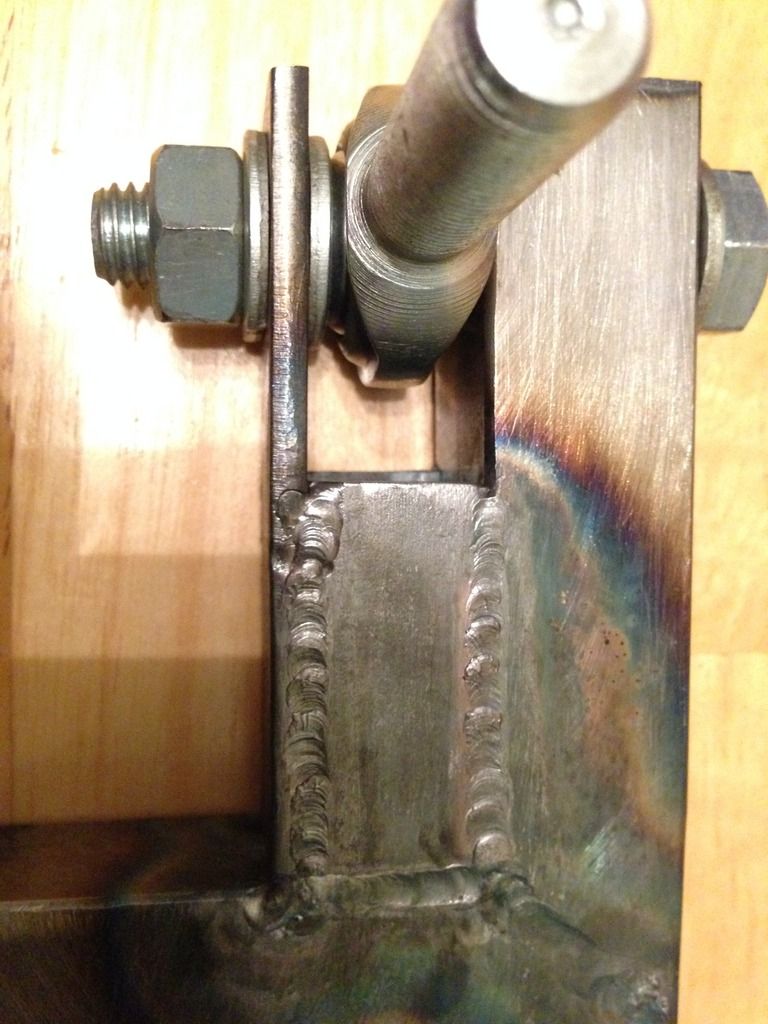
I have made this for adjusting my camber:
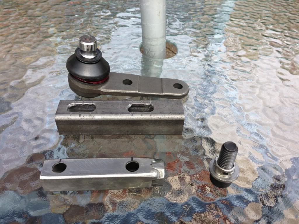
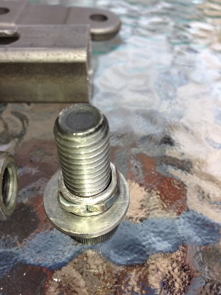
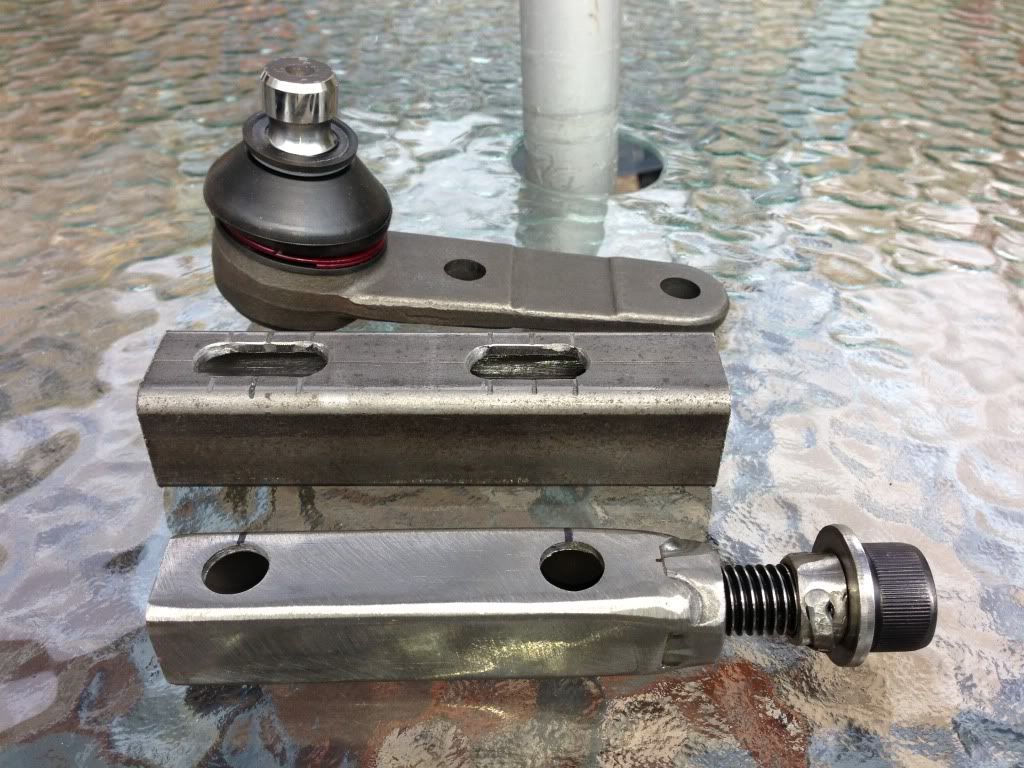
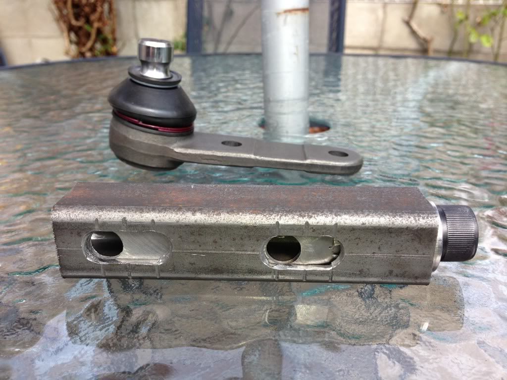
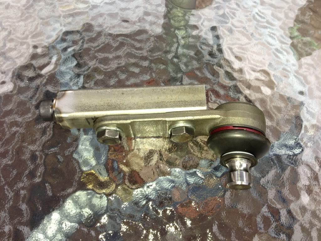
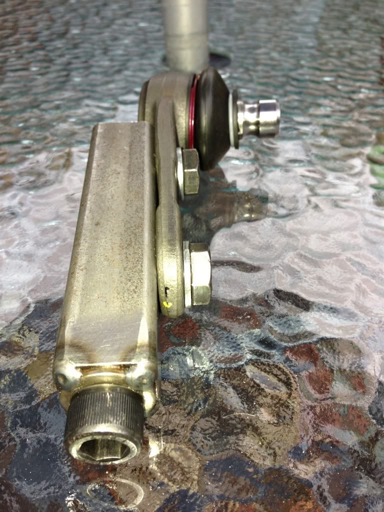
So now I need to make a new arm based around this, by turning the screw the ball joint is adjust in and out, then you just lock up the two bolts, took
a bit of making but seems to work very well.
Rob
[Edited on 27/7/13 by b14wrc]
20vt powered rear engined locost
|
|
|
b14wrc
|
| posted on 28/7/13 at 10:37 AM |
|
|
20vt powered rear engined locost
|
|
|
Uphill Racer
|
| posted on 28/7/13 at 10:37 PM |
|
|
Are you sure your figures on negative camber are right?
I know pics can give a false view but from them it looks like the arcs send the upright into positive camber.
|
|
|
b14wrc
|
| posted on 29/7/13 at 11:39 AM |
|
|
Hi uphill racer,
Thanks for your comments. Are you looking at the graph results? Wondering where your thoughts for the camber issue came from. That graph refers to the
old set up I havent yet tested the new arrangement to the same accuracy and graphed the results. However I have done a quick check on the current
set up with my angle gauge and it defiantly does increase in negative camber as the suspension moves through its range. Exactly how much the next
generation arm will give I am not yet sure, but before I was getting about 1.5deg of travel for about 2 of travel, this is similar to an Elise I
think I read so should be in the right ball park.
The new design should mean I can dial in the static camber very easily. The only issue I have at the moment is that the front pick up is too far out
board and the engine is going to have to move back for the mount to move inboard, this is doable though and plan to get the engine out this week and
get it completed by the weekend.
One other major change is the shock is going to have to move, probably mount on the arm rather than the hub as it is at the moment
Regards, Rob
20vt powered rear engined locost
|
|
|
b14wrc
|
| posted on 3/8/13 at 01:02 PM |
|
|
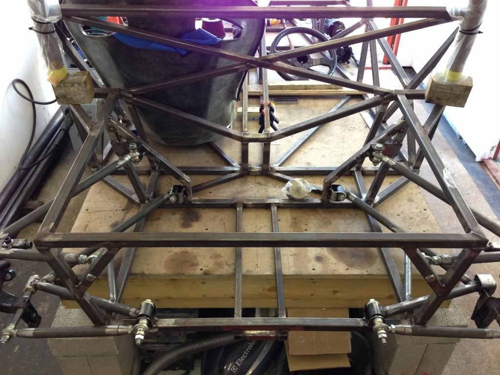
This is a better photo of the suspension angles. Not sure exactly what the ride height is going to be, I guess between 140-120mm, which means the
bottom arms will be level or slightly pointing down at rest.
Once I have made the final top arm incorporating my new camber adjusters, I can recalculate the camber gain, but from the position of the upper mount
points, I am expecting similar to before.
I've also fitted better front mounts for the top arms, once all welded, I think it will be pretty rugged.
Rob
20vt powered rear engined locost
|
|
|
b14wrc
|
| posted on 10/8/13 at 07:57 AM |
|
|
Hi,
Just a quickie:
Rob
20vt powered rear engined locost
|
|
|
b14wrc
|
| posted on 10/8/13 at 07:34 PM |
|
|
20vt powered rear engined locost
|
|
|
b14wrc
|
| posted on 11/8/13 at 07:01 PM |
|
|
[Edited on 11/8/13 by b14wrc]
20vt powered rear engined locost
|
|
|
Volvorsport
|
| posted on 11/8/13 at 07:20 PM |
|
|
are you running those hubs upside down for a reason ?
www.dbsmotorsport.co.uk
getting dirty under a bus
|
|
|
b14wrc
|
| posted on 11/8/13 at 07:26 PM |
|
|
Yes, I wanted the ball joint at the top and not the bottom.
Issue??
20vt powered rear engined locost
|
|
|
b14wrc
|
| posted on 4/2/14 at 10:18 PM |
|
|
20vt powered rear engined locost
|
|
|
b14wrc
|
| posted on 4/2/14 at 10:23 PM |
|
|
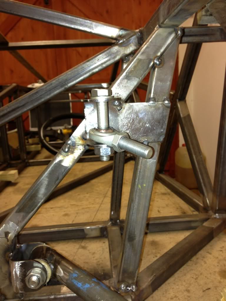
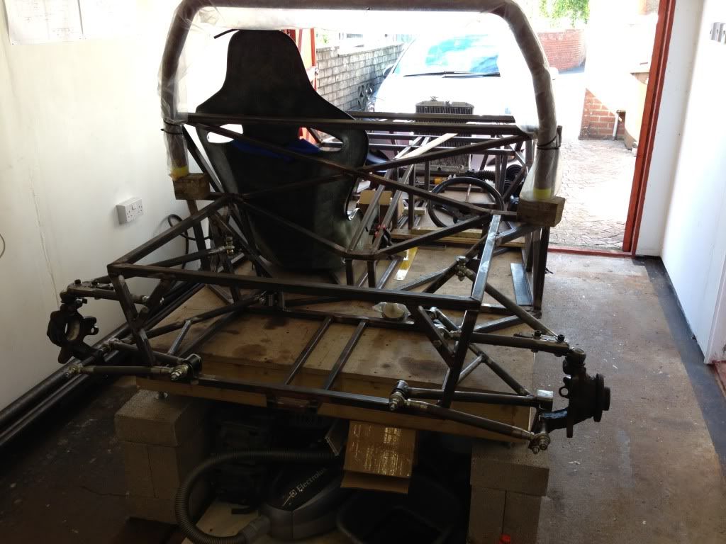
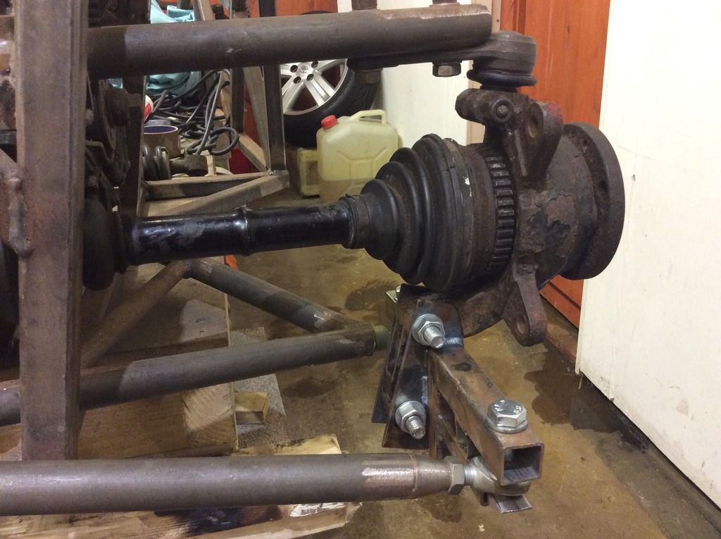
Hi all,
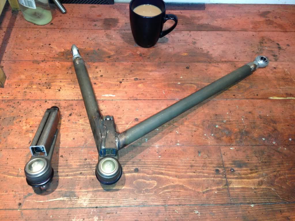
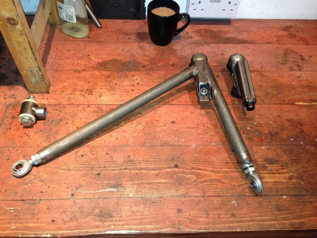
Managed to find a little time to work on the car last weekend. Upper rear arm now finally in place, I've welded a bracket onto the rear pick up
point so the rose joint sits in the correct plane of rotation.
And the square section joining the front rod on the wishbone is where the shock will mount. It's a neat solution I think....
Rob
20vt powered rear engined locost
|
|
|
nick205
|
| posted on 5/2/14 at 12:43 AM |
|
|
Hi Rob
Looking at the design I really think the rear upright will be prone to twisting under load. It just doesn't look right to me with the long bolt
as the pivot arrangement.
Would you not be less constrained if you fabricated your own uprights along the lines of how MK and others do it?
Meant constructively BTW
|
|
|
ashg
|
| posted on 5/2/14 at 02:07 AM |
|
|
sorry someone has got to say it that rear suspension setup is abysmal. the bottom long bolt is going to bend/twist from the engine torque. the inner
rear bolt is for the rear part of the lower arm is unsupported on one end so that will bend too.
pleas don't take my comments in a negative way i really don't want you to get hurt, what you have done is dangerous!
try doing it this way the fiat inner cv joint will most likely be 100mm or 108mm. remove the outer cv joint and put a inner joint on the outer part
of the driveshaft. that will give you a driveshaft end that should mate up to a sierra rear carrier/drive spline ( they come in 100 and 108mm) then
you can use a more conventional rear carrier like you see on most irs 7's and many other sports cars.
again sorry to throw a spanner in the works but the upright your trying to make use of is completely unsuitable. the only way the mojo is getting
away with such a poor design is the fact that the span of the lower bolt isn't so wide and it will make less than half the power of that coupe
5pot.
Anything With Tits or Wheels Will cost you MONEY!!
Haynes Roadster (Finished)
Exocet (Finished & Sold)
New Project (Started)
|
|
|
b14wrc
|
| posted on 5/2/14 at 07:18 AM |
|
|
Blunt!
Just so you know, the long bolt is being changed, I've started making the parts, it's going to be quite different, so if that's the
only area of concern I'm not that bothered. Also the two lower brackets are going to have some extra tubes joining to them, these will integrate
into the engine/gearbox mounts.
Looked at using ford uprights, the drive shafts don't match, so it's a non-starter.
20vt powered rear engined locost
|
|
|
b14wrc
|
| posted on 20/2/16 at 03:47 PM |
|
|
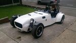
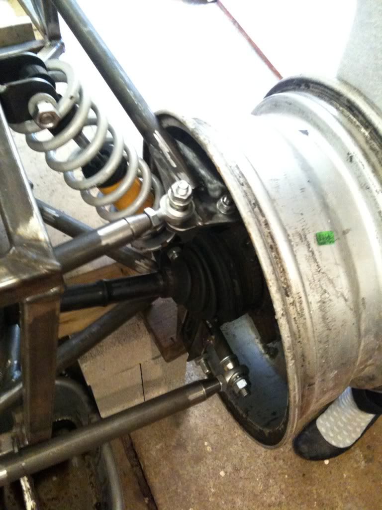
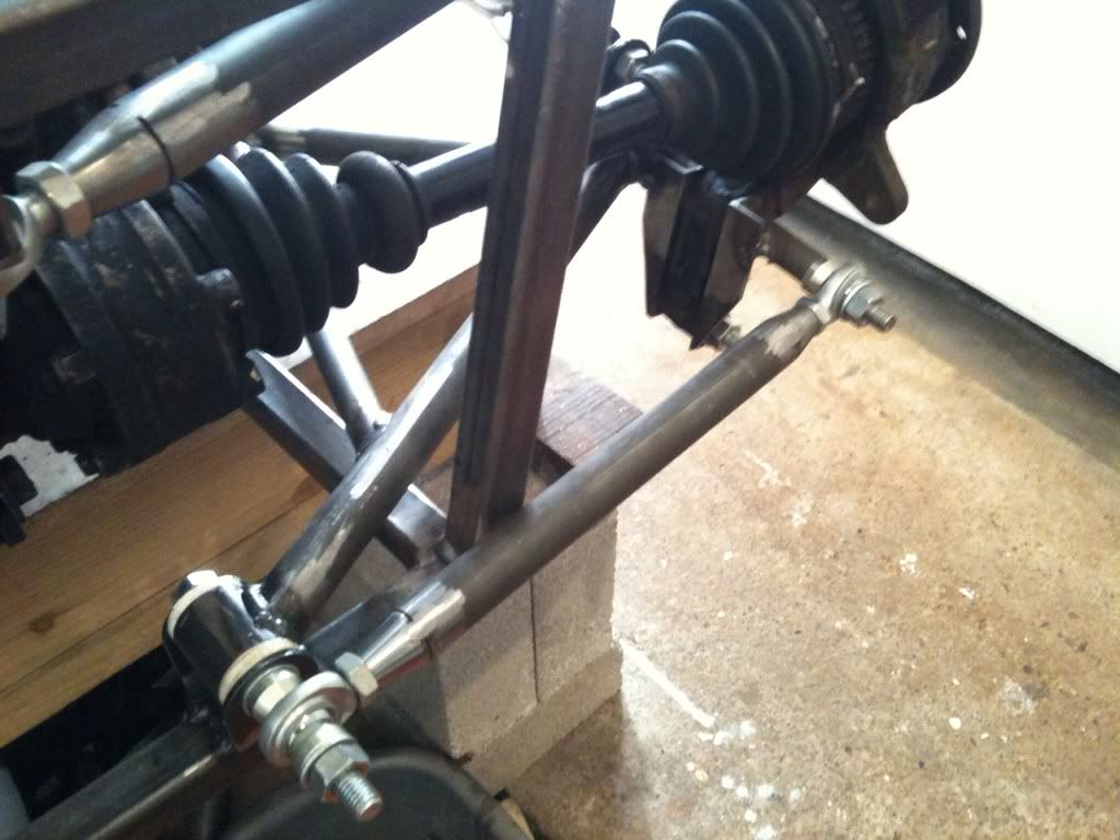
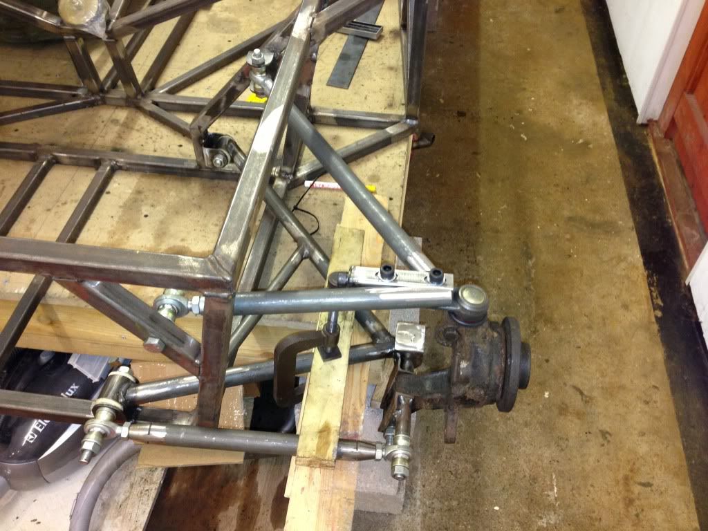
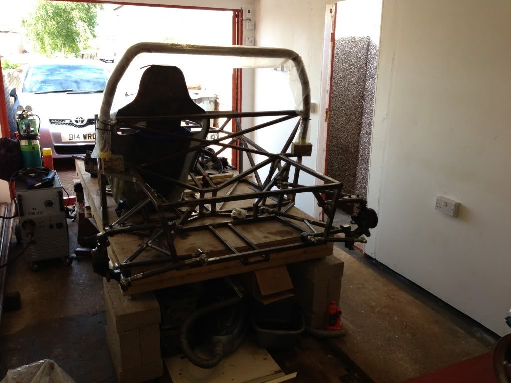
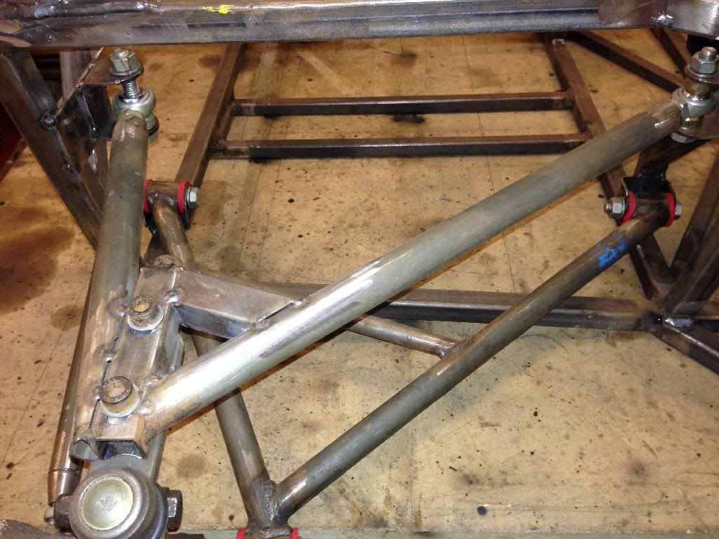
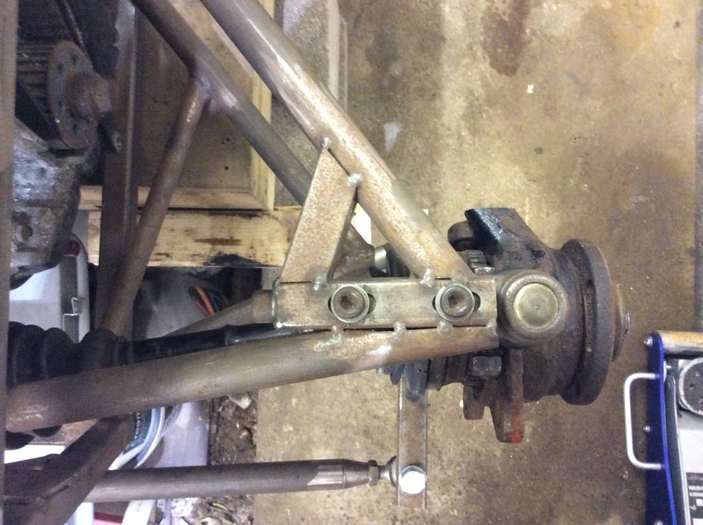
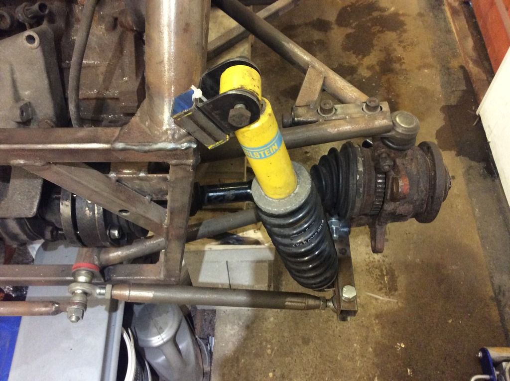
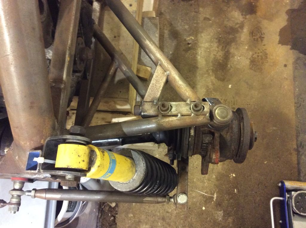
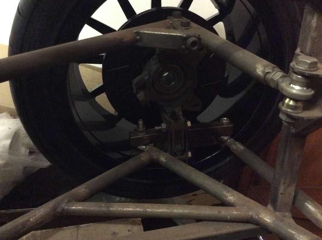
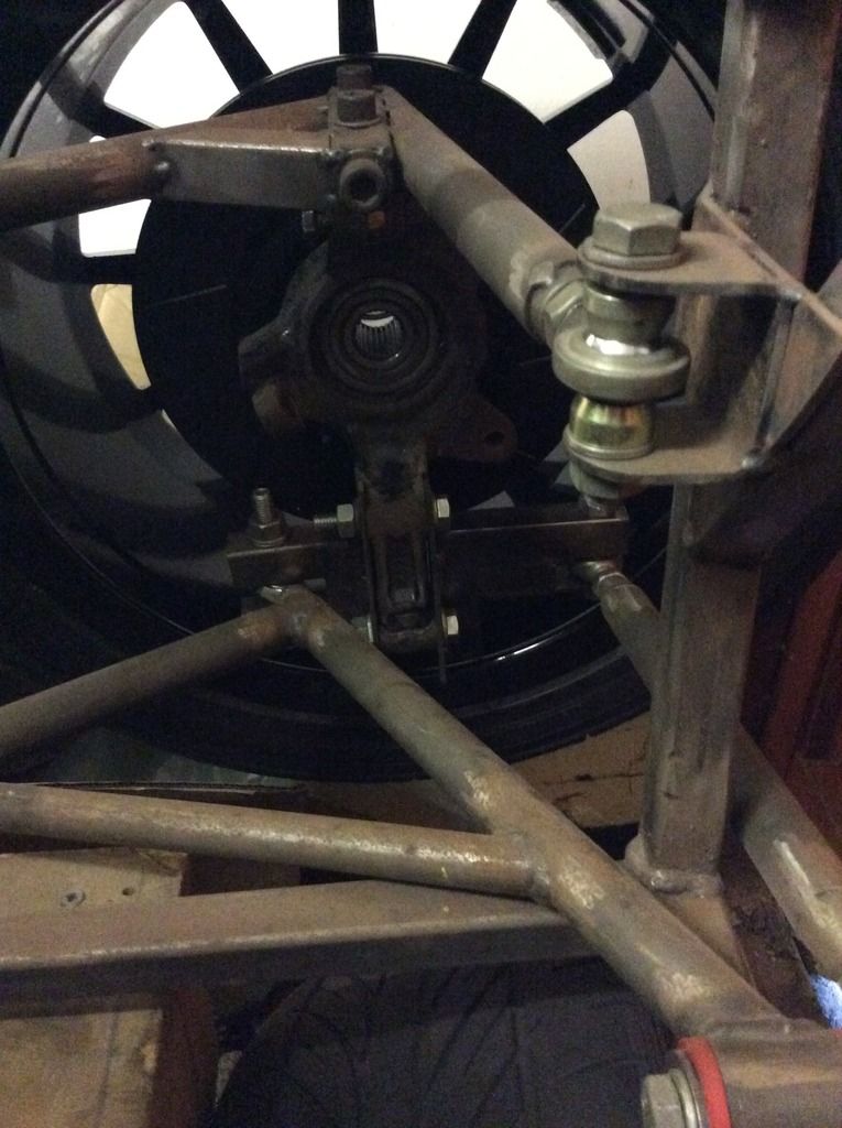
Hi All,
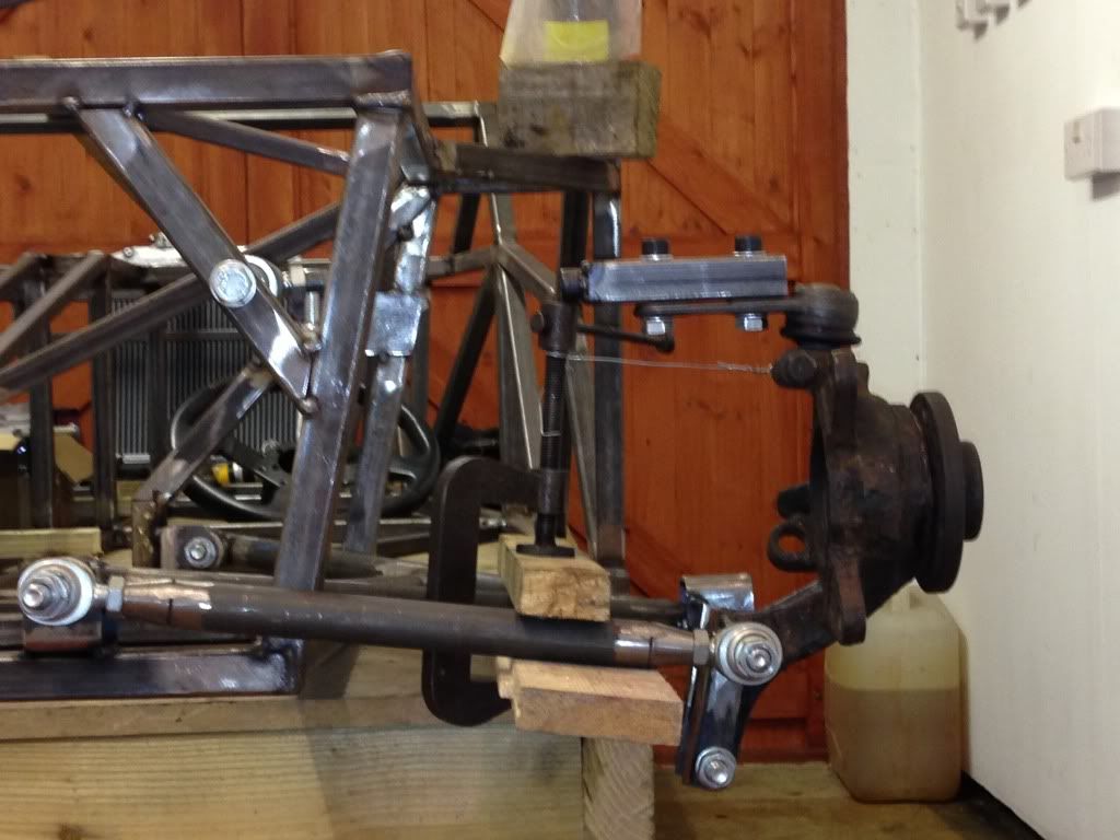
So it's been a long time since this thread started but I have had loads on and only got around to progressing a bit more on this. I need some
help and advice around mounting my shock, below are some photos to show progress. It's still not completely welded and it is still mock up, but
this is about the 5-6 rear suspension design and from an engineering point of view I am now pretty happy with it. It will have some additional steel
work added to link the two halves of the lower hub bracket and the wishbones are getting some extra steel. As said, my concerns are over position of
the shock, I'm thinking one of the mounts needs to be a rose joint if I go this way as when adjusting the track with both ends of the shock
being bushed I'll run into twisting issues?
I'd prefer it low down rather than mounting it to the top arm, can't mount to the bottom arm as the gearbox is in the way on the other
side! Lol
 [/UR] [/UR]
[URL=http://s1126.photobucket.com/user/b14wrc/media/EAE364B8-3508-4A86-822F-74AA3DE2D647.jpg.html]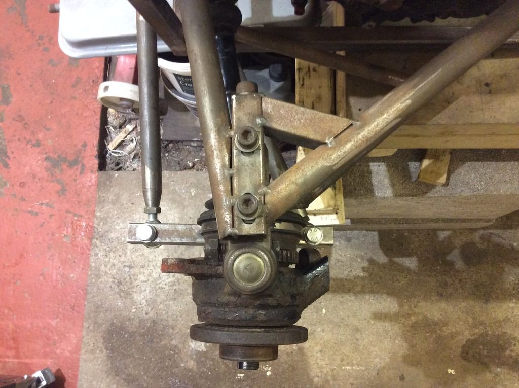
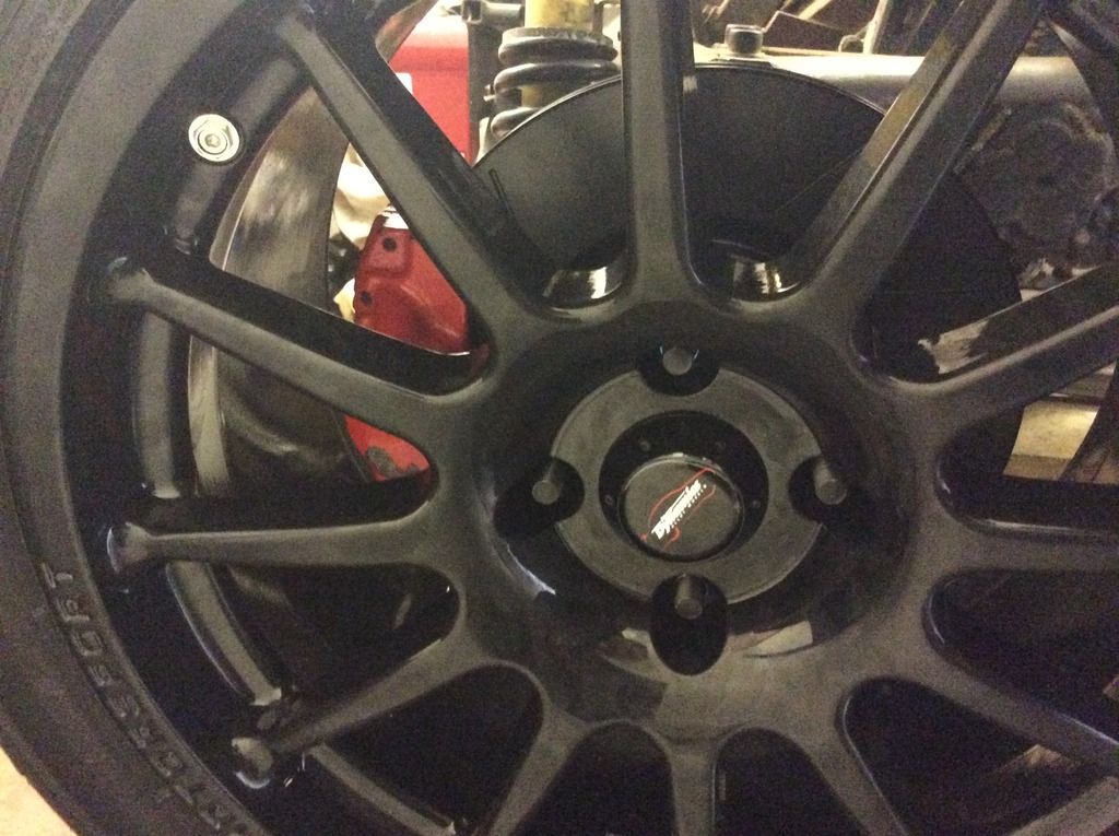
Let me know what your thoughts are. I've also got the rear brakes almost sorted....
Rob
20vt powered rear engined locost
|
|
|
b14wrc
|
| posted on 23/11/16 at 10:24 PM |
|
|
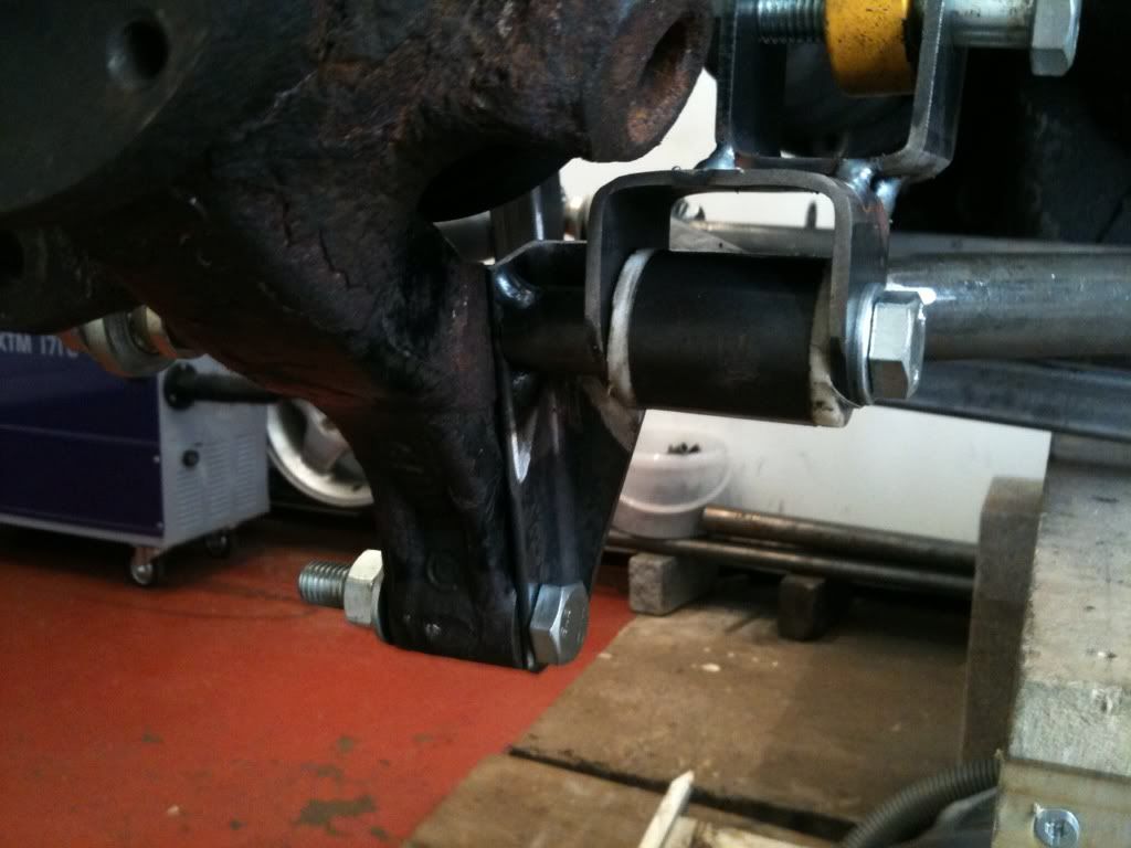
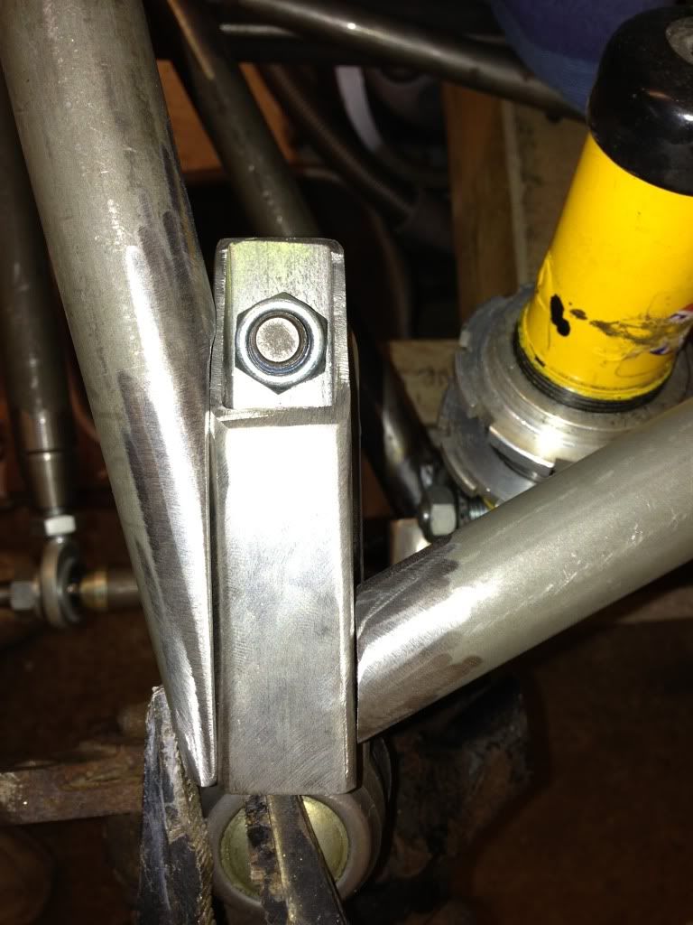
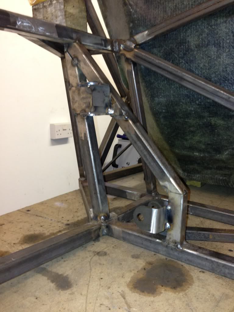
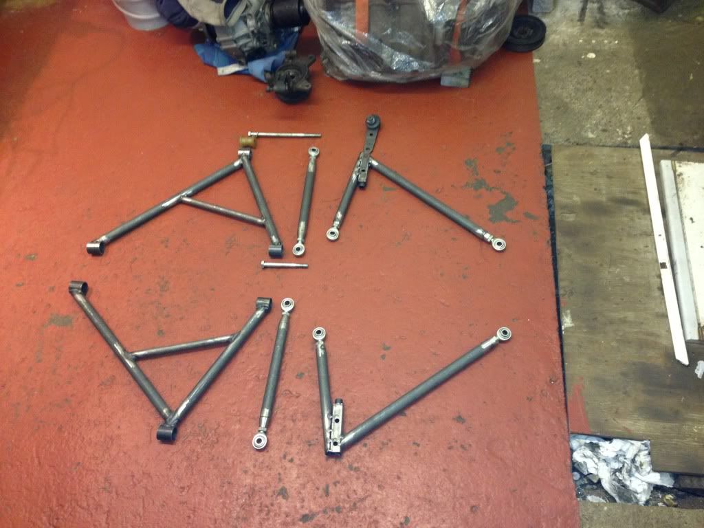
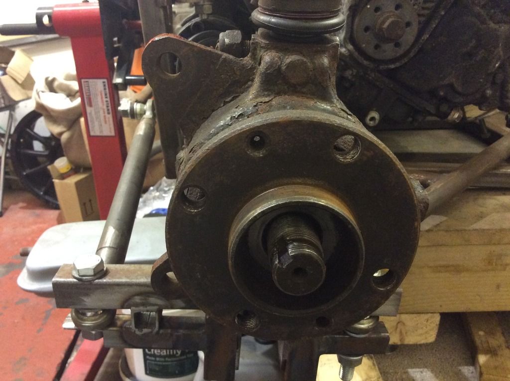
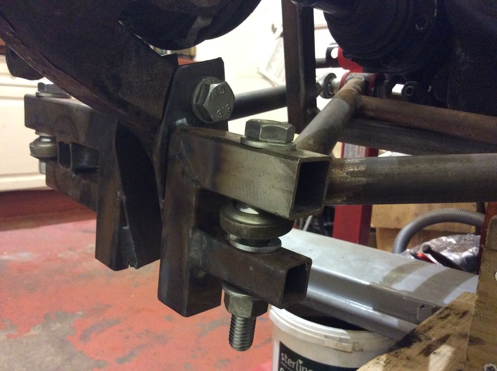
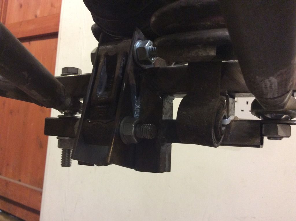
New bottom brackets/hub carriers.....
Weekend I'll be making a full new set same as these prototypes. Need to adjust hole positions slightly and make them easier to weld, getting the
TIG in was tricky, got some good ideas. Once these are finished, I'll mount the shocks to them and the chassis, completing the rear suspension
at last!
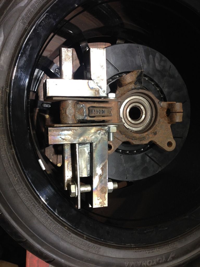
The photos show the old parts over laid to the old design, main issue was the closeness to the rim and the mods meant a nasty stress concentration at
the corner next to the bolt, basically rubbish so I've had to redo (several times).
20vt powered rear engined locost
|
|
|
Nickp
|
| posted on 24/11/16 at 07:43 AM |
|
|
quote:
Originally posted by b14wrc
Yes, I wanted the ball joint at the top and not the bottom.
Any particular reason?
|
|
|
b14wrc
|
| posted on 24/11/16 at 12:35 PM |
|
|
Hey,
Well for starters I am obviously not following the crowd with my engine choice. This kind of forced me to use the front wheel drive hubs, people
suggested ford but the drive shaft splines wouldnt align and to be honest I didnt want to get into hybrid drive shafts, I have made enough custom
bits so far and wanted fiat running gear straight through to ensure spares are easy to attain.
The reason for the ball joint at the top, well it could have gone at the bottom, but then you would need to mount some sort of arrangement to fit a
ball joint to the mcpearson strut holder (messy) or fit an arrangement to fit two wishbones to that part similar to what I have tried at the bottom. I
cut the steering arms off because A I didnt want bump steer issues, which I think I would have had as mounting points were limited, and B this way,
my heavy bits are lower down, in fact I reckon the solution is now pretty optimised, I get a comparable dynamic suspension travel to an Elise
(Actually Measured) and manage to package everything in around the 5 Cylinder nicely and still allow access for adjustment. Lotus run ball joints on
the top and bottom, which is king of what Im now going for with the rose joints.
The rose joints will eventually be booted inboard joints are PU. On my S1 Elise I had rose jointed toe links very similar set up to what I will
eventually have here, so dont see an issue.

20vt powered rear engined locost
|
|
|
b14wrc
|
| posted on 25/11/16 at 08:53 PM |
|
|
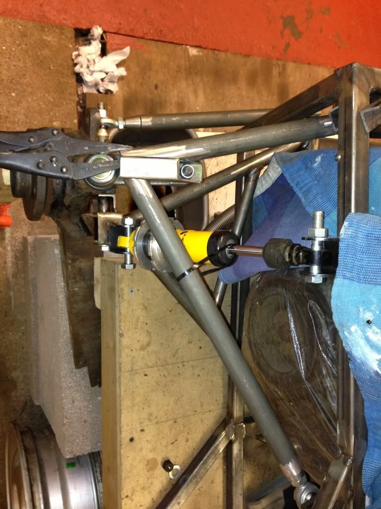
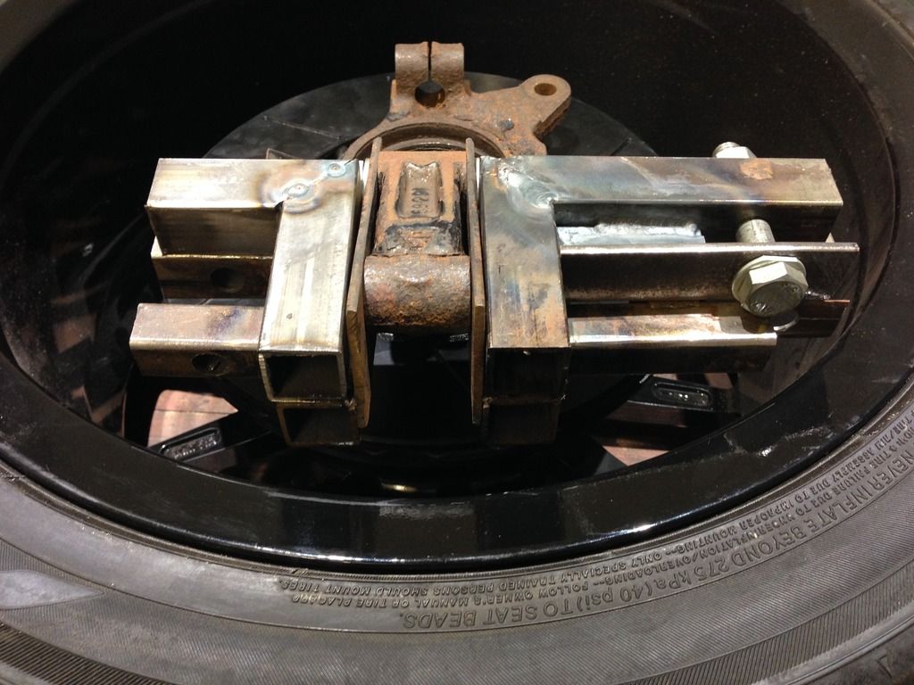
Pretty pleased with next stage on the hub carriers.
Rob
20vt powered rear engined locost
|
|
|
b14wrc
|
| posted on 26/11/16 at 01:03 PM |
|
|
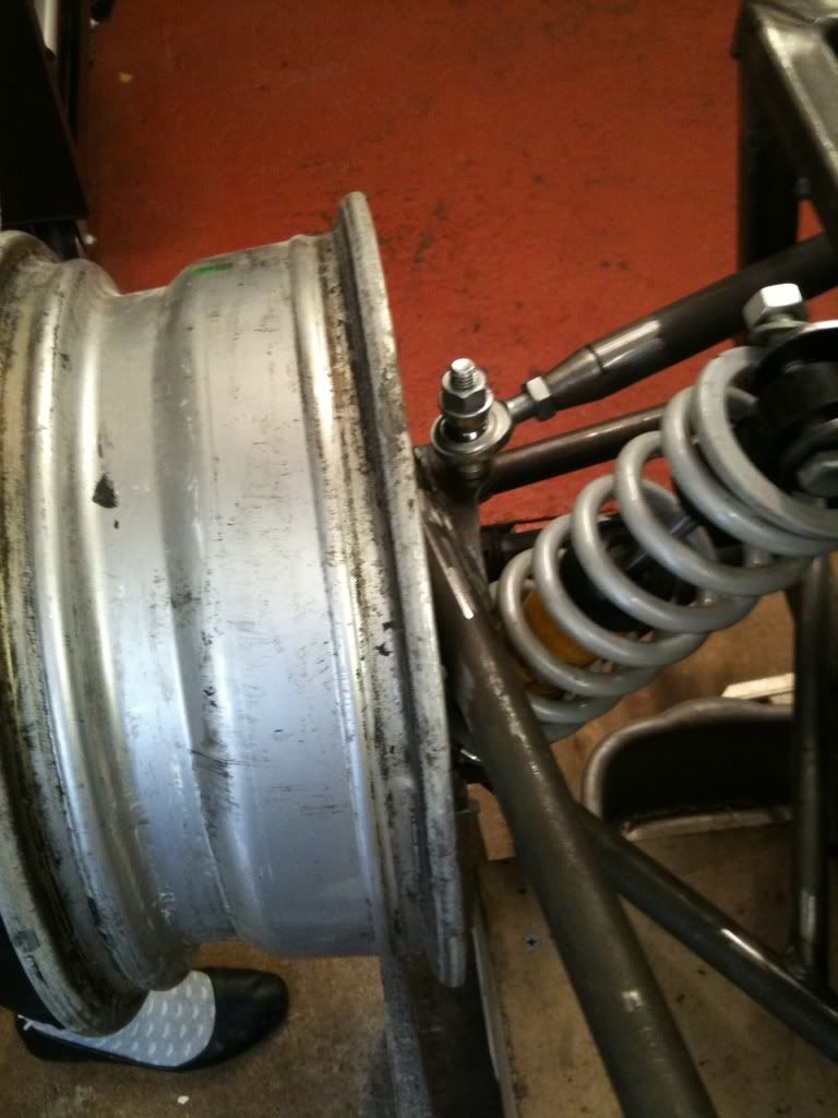
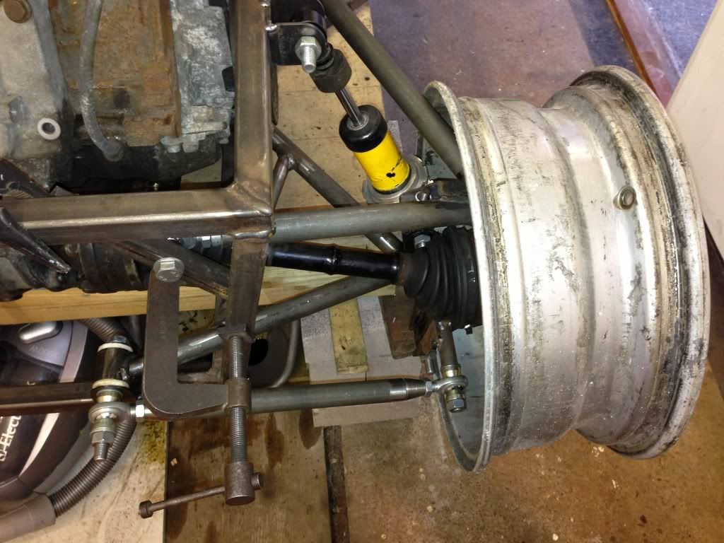
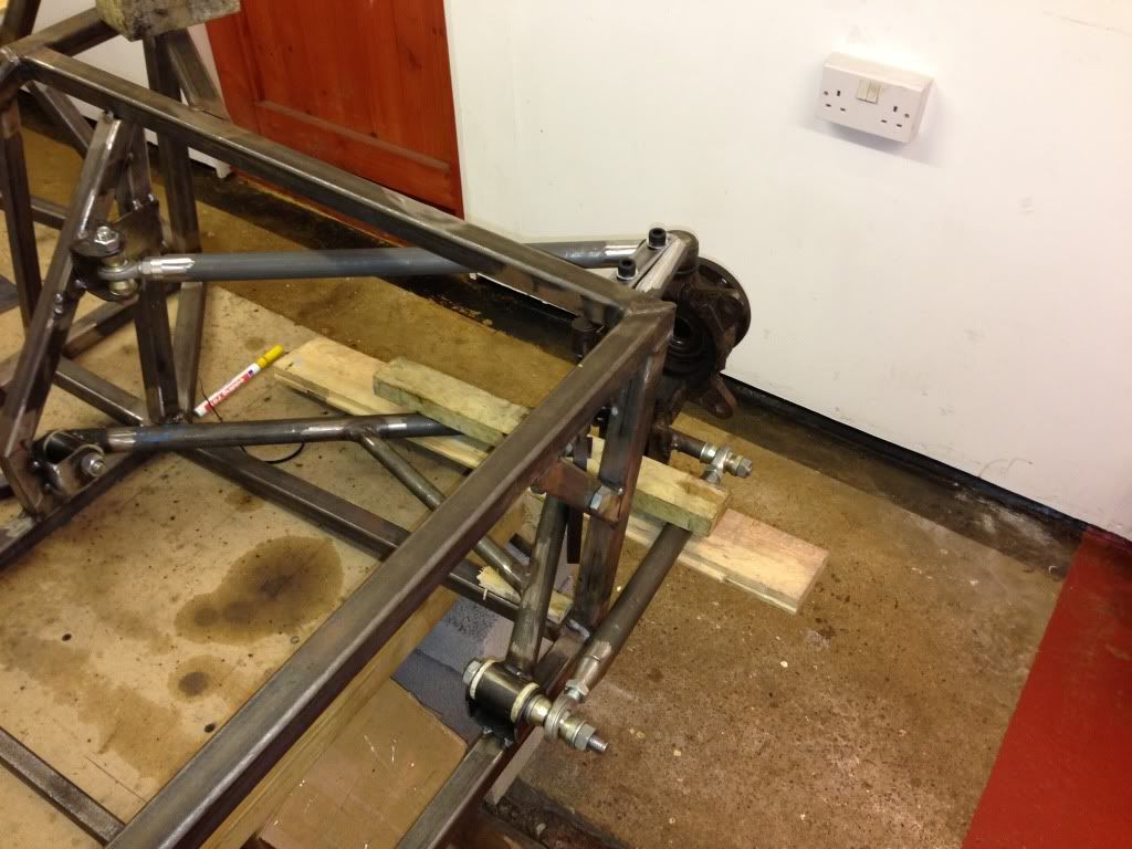
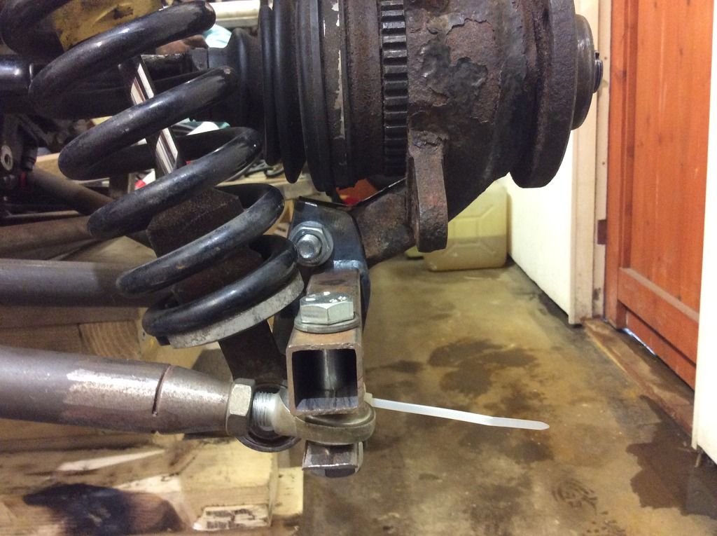
Installed the (not finished) new rear hub carrier. I will be making a new forward part then two brackets that will weld the two parts together.
Lengthening the forward part should also provide a slightly better angle for the rear toe arms. Once finished I will weld my shock mounts to the rear
section, going to rose joint that connection so there is ajustment when the toe is changed, if that makes sense...
Rob
20vt powered rear engined locost
|
|
|


 [/UR]
[/UR]