Bizarro
|
| posted on 26/10/11 at 08:04 PM |

|
|
Swirl pot, fuel layout
Thinking about the next job on my build and I want to get fuel tank and lines sorted. Im using a Zetec and plan on using bike TBs, my plan is:
LP pump - swirl pot - HP pump - HP filter - fuel rail - return to swirl pot
Ive had a good look using the search and just want to confirm Im thinking the right way when piping up my swirl pot:
Is this correct?
 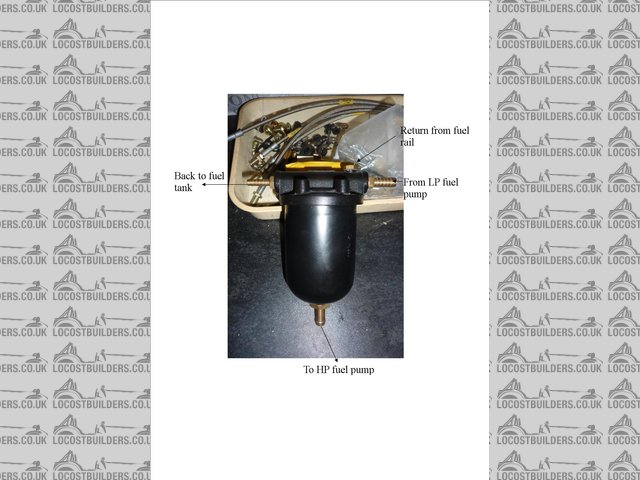
Description
On the fuel tank I assume that the small pipe at the top is for a breather, can I put the return in here and use a filler cap with breather built in
or do I need to drill another hole for the return?
 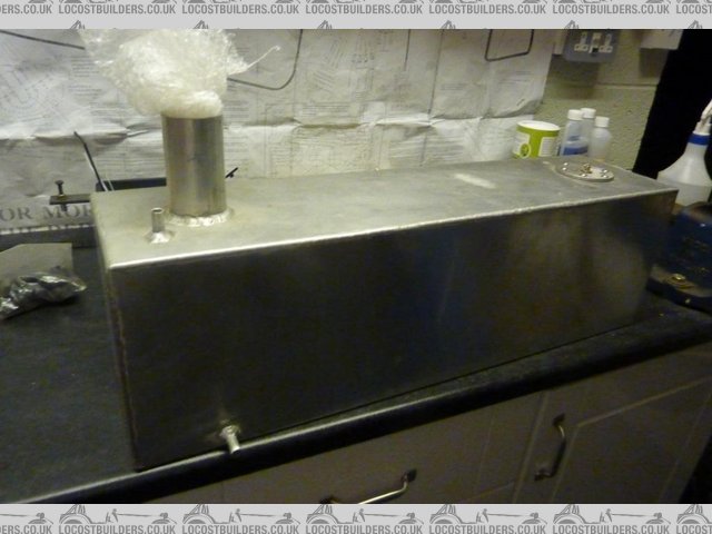
fuel tank
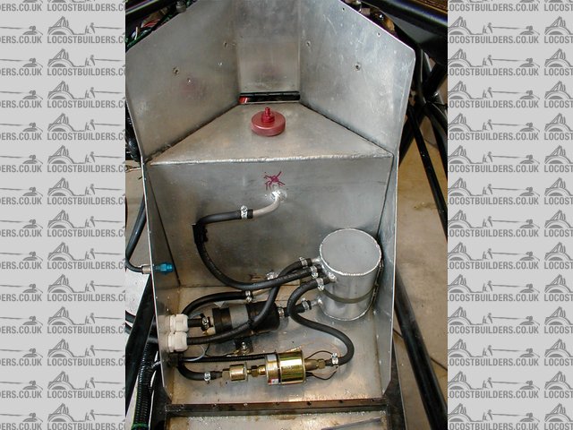
Originally I bought a part built kit so have a few parts that I dont know exactly what they are, how can I tell if a fuel pump is high or low
pressure?
I realise picture doesnt show anything but worth a shot:
 
While Im posting, anybody know what this is?
Cheers
|
|
|
|
|
bi22le
|
| posted on 26/10/11 at 08:11 PM |
|
|
The thing at the bottom looks like a vacum sharing thing. Allows the vacum signal from the TB to go lots of places.
Some one with a whole lot more knowledge will be a long shortly to correct me and stick a 'D' hat on my head. . . . .
Track days ARE the best thing since sliced bread, until I get a supercharger that is!
Please read my ring story:
http://www.locostbuilders.co.uk/forum/13/viewthread.php?tid=139152&page=1
Me doing a sub 56sec lap around Brands Indy. I need a geo set up! http://www.youtube.com/watch?v=EHksfvIGB3I
|
|
|
rb968
|
| posted on 26/10/11 at 08:13 PM |
|
|
Bottom one looks like a vacuum block to me....no expert though.
|
|
|
sky12042
|
| posted on 26/10/11 at 10:00 PM |
|
|
Think your filter needs to be before the pump, so the fuel is filtered before it reaches and possable damages the pump.
Andy
|
|
|
wombat
|
| posted on 27/10/11 at 05:54 AM |
|
|
Handy post, was thinking of the same earlier in week in preparation for mine.
Using GSXR600 TBs with ST170 inlet manifold as previous advice on here.
Would be really helpful to have the layout sorted in my head
e.g. Tank to ? to ? etc
Flak Monkey can supply fuel rail at good price or you can modify ST rail.
Send me u2u with e-mail address and I will forward info these guys have sent me so far regarding TBs to ST inlet, really useful with pics etc
|
|
|
Norfolkluegojnr
|
| posted on 27/10/11 at 08:22 AM |
|
|
http://www.fatbaldbloke.co.uk/westfield_articles/Westtbs.html
Useful linky. Think Fatbaldbloke might be a member on here? anyway, a thorough write up with some decent pics.

|
|
|
Bizarro
|
| posted on 27/10/11 at 09:15 AM |
|
|
quote:
Originally posted by Norfolkluegojnr
http://www.fatbaldbloke.co.uk/westfield_articles/Westtbs.html
Useful linky. Think Fatbaldbloke might be a member on here? anyway, a thorough write up with some decent pics.
Very good link, thanks
Wombat u2u sent, thanks
|
|
|
Bizarro
|
| posted on 27/10/11 at 09:23 AM |
|
|
quote:
Originally posted by bi22le
The thing at the bottom looks like a vacum sharing thing. Allows the vacum signal from the TB to go lots of places.
Some one with a whole lot more knowledge will be a long shortly to correct me and stick a 'D' hat on my head. . . . .
You can borrow my hat, already has a 'D' on it
Out of interest, apart from ECU pressure sensor and possible fuel presssure regulator, where else would you need to send vacuum signal to?
|
|
|
adithorp
|
| posted on 27/10/11 at 12:31 PM |
|
|
The swirl pot... Don't know as never seen on like that and don't have one myself; I just have a baffled well on the bottom of the tank.
The usual order is tank pick up > LP pump > swirl pot > lp filter > HP pump> HP filter > fuel rail > rail return > swirl pot
> swirl pot return > tank.
On the tank... That could be either a return or a breather. Personally I 'd fit another for return and use that as the breather with a 2 way
valve fitted rather than a breather cap. If thats the pick up at the bottom on the end, then it will suffer from starvation when cornering one way, so
might be worth considering using that as return and putting a new one near the middle for pick up.
The pump... Yes thats a high presure pump and is probably rated at 3bar like most. It should have an injection filter after the pump. It will also
want a pre-pump filter before it. Either a gauge on the pick uppipe as tin-tops have will do or a low presure filter in the line (just be sure
it'll allow enough flow or it'll cavitate and create air bubbles).
"A witty saying proves nothing" Voltaire
http://jpsc.org.uk/forum/
|
|
|
Bizarro
|
| posted on 27/10/11 at 03:28 PM |
|
|
quote:
Originally posted by adithorp
The swirl pot... Don't know as never seen on like that and don't have one myself; I just have a baffled well on the bottom of the tank.
The usual order is tank pick up > LP pump > swirl pot > lp filter > HP pump> HP filter > fuel rail > rail return > swirl pot
> swirl pot return > tank.
On the tank... That could be either a return or a breather. Personally I 'd fit another for return and use that as the breather with a 2 way
valve fitted rather than a breather cap. If thats the pick up at the bottom on the end, then it will suffer from starvation when cornering one way, so
might be worth considering using that as return and putting a new one near the middle for pick up.
The pump... Yes thats a high presure pump and is probably rated at 3bar like most. It should have an injection filter after the pump. It will also
want a pre-pump filter before it. Either a gauge on the pick uppipe as tin-tops have will do or a low presure filter in the line (just be sure
it'll allow enough flow or it'll cavitate and create air bubbles).
Thanks for the info, I will have a look in the tank as from memory I think the tank has a baffle fitted about at the centre. Just a thought but doesnt
the return need to be at the top of the tank? If I put the return in the bottom of the tank I will be trying to push fuel against the fuel in the
tank?
|
|
|
adithorp
|
| posted on 28/10/11 at 07:57 AM |
|
|
Going into the bottom then yes, it has to over come the pressure from of the height of fuel in the tank. To go in the top it has to overcome pumping
to the top of the tank. In reality the 2 are the same... except as the tank empties the height of fuel in the tank reduces.
Going into the top of the tank for most of the time it'll be spraying into the air space above the fuel and the amount of vapor created (and
presure in the tank) will be more than if going into the bottom.
"A witty saying proves nothing" Voltaire
http://jpsc.org.uk/forum/
|
|
|
mrwibble
|
| posted on 29/10/11 at 12:01 PM |
|
|
anyone explain this from fatbaldblokes website
"There's one trick here I'm going to pass on. The delivery flow rate (and hence the rate of the ticking noise) from the low pressure
pump is regulated by the back pressure it has to pump against. In the normal course of events when it's feeding a carburettor or two and the
float chamber needle valves close, the back pressure increases and the pump stops ticking away. In the system I've described where all the LP
pump does is keep the swirl pot topped up there's very little back pressure so the pump ticks away like mad. The trick is to fit a small
orifice, around 1.0 - 1.2mm in the return line from the swirl pot to the tank, to limit the flow. This will slow the LP pump down to a
not-too-intrusive ticking rate."
An orifice to my mind means a hole, does the guy mean an obstruction, like a dimple in the pipe?
|
|
|
lsdweb
|
| posted on 29/10/11 at 01:04 PM |
|
|
My setup in my single seater (long gone). The HP filter is in the line to the TB's.
Swift Fuel
Wyn
|
|
|
fatbaldbloke
|
| posted on 30/10/11 at 08:38 AM |
|
|
quote:
anyone explain this from fatbaldblokes website
Hello, I think I can probably explain this.... (sorry, don't get on this site as often as I once did, new project on the go).
Normally the low pressure pump supplies carbs and as the float chamber fills and the needle valve seals the backpressure increases and the pump slows
down until it is just supplying only the fuel the carbs need, so it ticks every few seconds. On the other hand if you allow completely free flow from
an LP pump it will run flat out and tick 5 or 6 times a second, which is quite irritating and will potentially also increase wear and tear. In the
EFI type installation where the LP pump simply supplies a swirl pot there is effectively no restriction to flow, so it will run in this full flow
condition. So, to slow it down to a more acceptable rate you need to provide a bit of resistance for it to pump against, hence a restriction in the
pipe from the swirl pot back to the tank. I used a bar with a small hole (orifice) drilled in it and clamped inside a length of hose. (In a bit more
detail, as I recall it was 8mm dia bar about 50mm long. Drilled through with a 5mm bore apart from the final 4mm or so. Then a 1mm hole through this
last bit.) I guess you can squeeze the pipe a bit if you want or any other way of constricting flow, it's just a bit cruder than a machined
orifice.
Does that make sense?
[Edited on 30/10/11 by fatbaldbloke]
|
|
|
mrwibble
|
| posted on 31/10/11 at 01:46 PM |
|
|
quote:
Originally posted by fatbaldbloke
quote:
anyone explain this from fatbaldblokes website
Hello, I think I can probably explain this.... (sorry, don't get on this site as often as I once did, new project on the go).
Normally the low pressure pump supplies carbs and as the float chamber fills and the needle valve seals the backpressure increases and the pump slows
down until it is just supplying only the fuel the carbs need, so it ticks every few seconds. On the other hand if you allow completely free flow from
an LP pump it will run flat out and tick 5 or 6 times a second, which is quite irritating and will potentially also increase wear and tear. In the
EFI type installation where the LP pump simply supplies a swirl pot there is effectively no restriction to flow, so it will run in this full flow
condition. So, to slow it down to a more acceptable rate you need to provide a bit of resistance for it to pump against, hence a restriction in the
pipe from the swirl pot back to the tank. I used a bar with a small hole (orifice) drilled in it and clamped inside a length of hose. (In a bit more
detail, as I recall it was 8mm dia bar about 50mm long. Drilled through with a 5mm bore apart from the final 4mm or so. Then a 1mm hole through this
last bit.) I guess you can squeeze the pipe a bit if you want or any other way of constricting flow, it's just a bit cruder than a machined
orifice.
Does that make sense?
[Edited on 30/10/11 by fatbaldbloke]
I wouldnt have the skills or tools to produce a machined piece of pipe like that, but i do understand what your getting at.
Many thanks. Ed.
|
|
|