Ron Lang
|
| posted on 1/1/17 at 01:11 PM |

|
|
Engine Harness Connector Terminal Identification
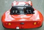
So the engine harness build fiasco continues. It's taken me weeks to identify how everything works and what is connected to what. I now have the
emerald to replace the megasquirt and a large diagram of what the harness should look like. Unfortunately, whilst I know the wiring runs, i have no
way to identify which terminal is which on the various connectors. For example, how do I which of the throttle position sensor terminals is 5v and
which is signal? The existing megasquirt connector was such a mess that I can even work back.
I'm not sure if I've explained that very well...
|
|
|
|
|
avagolen
|
| posted on 1/1/17 at 01:22 PM |
|
|
Hi,
To check the throttle pot, you will need a multi meter. Set it on ohms - resistance checking.
Measure between any two wires and move the throttle shaft. If you get a change in the reading,
you have the wiper and one end. Test again with another combination of wires and eventually you will
find the ends of the pot and the wiper. If your ECU requires 0 to 5 volts, connect the ground wire to the
wire that has the lowest resistance to the wiper when the throttle is closed and the 5 volts to the other wire.
Hope this helps.
The Answer for everything, but never the last word....
|
|
|
Ron Lang
|
| posted on 1/1/17 at 01:32 PM |
|
|
quote:
Originally posted by avagolen
Hi,
To check the throttle pot, you will need a multi meter. Set it on ohms - resistance checking.
Measure between any two wires and move the throttle shaft. If you get a change in the reading,
you have the wiper and one end. Test again with another combination of wires and eventually you will
find the ends of the pot and the wiper. If your ECU requires 0 to 5 volts, connect the ground wire to the
wire that has the lowest resistance to the wiper when the throttle is closed and the 5 volts to the other wire.
Hope this helps.
Sorry, what is wiper?
|
|
|
avagolen
|
| posted on 1/1/17 at 01:48 PM |
|
|
Sorry, bit difficult to explain.
The wiper is the part of the potentiometer that
picks up the position of the shaft.
It 'wipes' across the surface of the resistor giving
the variable signal.
The Answer for everything, but never the last word....
|
|
|
CosKev3
|
| posted on 1/1/17 at 01:48 PM |
|
|
If the wiring is that bad surely you will be better off starting from scratch and building yourself a new engine loom?
|
|
|
Ron Lang
|
| posted on 1/1/17 at 02:18 PM |
|
|
quote:
Originally posted by CosKev3
If the wiring is that bad surely you will be better off starting from scratch and building yourself a new engine loom?
That's the plan yes. But was hoping to use the connectors to save cost. And if I bought new connectors I still wouldn't know which
terminal was which.
|
|
|
CosKev3
|
| posted on 1/1/17 at 03:02 PM |
|
|
Pretty sure if you Google the sensors/switches etc it will show you which terminal does what! 
|
|
|
turnipfarmer
|
| posted on 1/1/17 at 04:28 PM |
|
|
I've got quite a bit of documentation on Ford connectors. So if that's what they are...
let me know which connectors you're using, I might be able to tell you which pin does what.
|
|
|
Ron Lang
|
| posted on 1/1/17 at 05:42 PM |
|
|
quote:
Originally posted by turnipfarmer
I've got quite a bit of documentation on Ford connectors. So if that's what they are...
let me know which connectors you're using, I might be able to tell you which pin does what.
That would be great. I'll take some pictures of the connectors later. I'm not sure what they are tbh.
|
|
|
Ron Lang
|
| posted on 1/1/17 at 07:37 PM |
|
|
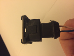
Injector Connectors:
Injector Connector
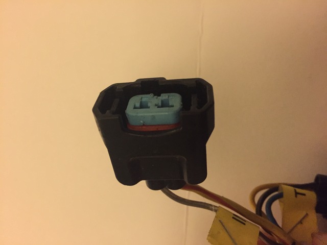
Throttle Pos Connector:
TPS Connector
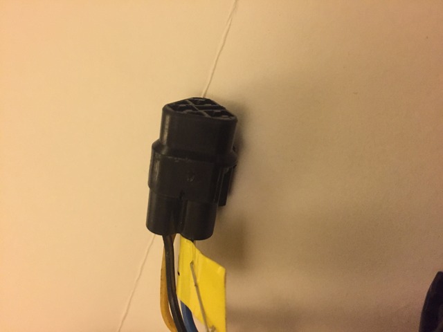
Stat/Air Temp/Crank Connector:
 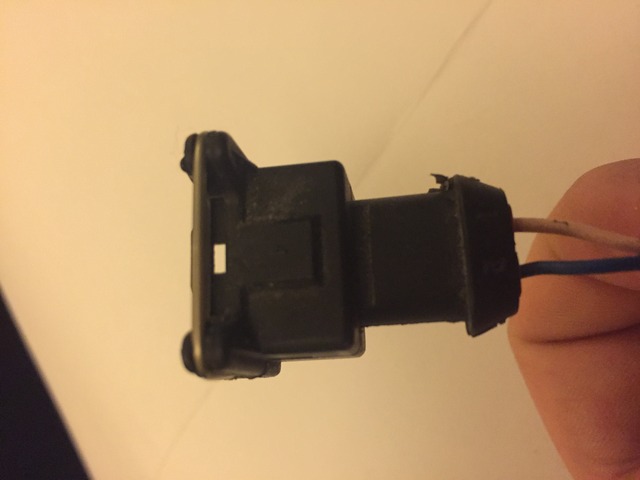
Stat/ATS/CPS Connector
Looking at these more closely, I realise the only way I could reuse them is to splice onto the existing cables which are not in great condition. May
be better to buy new ones depending on cost.
|
|
|
gremlin1234
|
| posted on 1/1/17 at 07:52 PM |
|
|
quote:
Originally posted by Ron Lang
Looking at these more closely, I realise the only way I could reuse them is to splice onto the existing cables which are not in great condition. May
be better to buy new ones depending on cost.
you may be able to change the individual connector pins, and keep the housing
|
|
|
nickm
|
| posted on 1/1/17 at 08:11 PM |
|
|
Hi
As gremlin said, but it will take a while to remove the whatever pin/connectors are in them. All the connectors will have a small tab to retain them
in the housing and if you look there will normally be a little excess groove slot for you to insert a tool along the length of the connector to
release the tab then pull them out easier said than done though ! it will drive you nuts.
Look at Vehicle Wiring Products website to identify what type of connector is it then buy twice as many as you need so you can practice crimping them
! and reinsert.
The crank sensor may have to be shielded cable to stop interference in the signal.
Hope this helps
Nick M
|
|
|
Ron Lang
|
| posted on 1/1/17 at 08:17 PM |
|
|
So you can't buy them with the housing? Is the housing car/engine specific?
Had a quick look but couldn't see how to remove the pins. Will look again...
|
|
|
Ron Lang
|
| posted on 1/1/17 at 08:44 PM |
|
|
Looks like these might be the stat/air/crank plugs:
http://www.emeraldm3d.com/connectors/2-pin-junior-mini-timer-plug.html
No luck with others yet.
|
|
|
gremlin1234
|
| posted on 1/1/17 at 08:59 PM |
|
|
quote:
Originally posted by Ron Lang
Looks like these might be the stat/air/crank plugs:
http://www.emeraldm3d.com/connectors/2-pin-junior-mini-timer-plug.html
No luck with others yet.
try
http://www.polevolt.co.uk/acatalog/Junior_Power_Timer_Connectors.html
|
|
|
turnipfarmer
|
| posted on 2/1/17 at 01:59 PM |
|
|
Ron
u2u me your email address & I'll send you a pdf you may find useful
|
|
|
Schrodinger
|
| posted on 3/1/17 at 09:40 PM |
|
|
how many pins do you need?
iirc I have some male and female in my garage and I can send you a few.
If you have the loose pins it might be a bit more obvious how they should be removed.
If this is any help u2u me with your address.
Keith
Aviemore
|
|
|
Ron Lang
|
| posted on 3/1/17 at 10:10 PM |
|
|
quote:
Originally posted by Schrodinger
how many pins do you need?
iirc I have some male and female in my garage and I can send you a few.
If you have the loose pins it might be a bit more obvious how they should be removed.
If this is any help u2u me with your address.
That's really kind thank you. Which connectors are they from?
I think we've established that most of the connectors (CPS, stat, coil pack etc) are Ford, but that the injector and TPS connectors are probably
from the Hyabusa TB's. I should be able to get hold of the ford ones (you'd think) but the others are a mystery.
|
|
|
lsdweb
|
| posted on 4/1/17 at 08:53 AM |
|
|
The bottom one is probably a junior power timer connectors. Removing the pins is a bit of a nightmare and not worth it as these are so cheap to buy -
4 x Fuel injector plugs with boots - Bosch EV1 2 pin - Mini Timer - Cosworth etc
Regards
Wyn
[Edited on 4/1/17 by lsdweb]
[Edited on 4/1/17 by lsdweb]
|
|
|
lsdweb
|
| posted on 4/1/17 at 09:02 AM |
|
|
And the injector ones look a lot like these -
1 X Honda / Acura S2000 Type R Suzuki GSXR Fuel Injector Connector Plug
|
|
|
Schrodinger
|
| posted on 4/1/17 at 02:17 PM |
|
|
quote:
Originally posted by Ron Lang
quote:
Originally posted by Schrodinger
how many pins do you need?
iirc I have some male and female in my garage and I can send you a few.
If you have the loose pins it might be a bit more obvious how they should be removed.
If this is any help u2u me with your address.
That's really kind thank you. Which connectors are they from?
the pins are from the mini timer type iirc
you are welcome to a few to try them, they may possibly fit the ford plug as well.
Keith
Aviemore
|
|
|