james h
|
| posted on 2/2/16 at 04:51 PM |

|
|
Wiring issue
Afternoon,
I've had an ongoing issue with a lack of a speedo due to electrical gremlins. I'm another step closer to fixing it (i think) - but not
just yet!
The speedo works off a Hall Effect sensor, which consists of three wires. One of which (white) also connects to the clocks and the ignition control
unit (CDI). With the ignition on, this should be at 5v. It isn't! It's 12V. So to isolate this white wire I disconnected:
1. The speedo sensor
2. The clocks
3. The Ignition control unit (CDI)
With the ignition OFF there is a short to earth. With it ON there is infinite resistance (open circuit?) but 12V!
I haven't unwrapped the loom yet, it's pretty tucked away. But what on earth (pun intended) could be going on? Anyone had something
similar?
P.s I've had a weird issue with the gear indicator (which takes a feed off this white wire) where with the engine running it would flicker a
lot. But not when I disconnected the stator/alternator and ran it as a total loss system. Then it would be fine - the car just wouldn't be
charging. Now the speedo just won't work at all. I've disconnected the gear indicator, shift lights and speedohealer when doing the above
checks.
[Edited on 2/2/16 by james h]
|
|
|
|
|
coozer
|
| posted on 2/2/16 at 07:08 PM |
|
|
Try feeding them by running a wire to the battery and see what happens. If that doesn't fix it maybe an earth problem...
1972 V8 Jago
1980 Z750
|
|
|
britishtrident
|
| posted on 2/2/16 at 08:15 PM |
|
|
Part of the problem would appear to be excessive alternator ripple or loose alternator connection cause drop outs it can play havoc with digital
systems.
This is an oscilloscope trace of the good alternator output voltage wave form of the alternator on my tintop --- measured directly on the output B_
terminal of the alternator.
 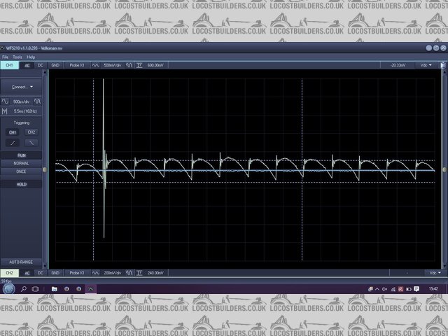
Denso Alternator Ripple - GOOD
The very sharp pikes aren't important what is important is that none of the rounded voltage humps are missing or dip down well below the
average.
The best test is to use an an oscilloscope to capture both voltage and current (using a DV current clamp) of the alternator under load but you can
use a normal DMM set to AC mV scale for a rough and reday test,
See these links --
Link 1 -- Youtube Alternator Ripple Testing -- Scannerdanner
Link 2 -- Peoples Garage Youtube video
[Edited on 2/2/16 by britishtrident]
[Edited on 2/2/16 by britishtrident]
[I] What use our work, Bennet, if we cannot care for those we love? .
― From BBC TV/Amazon's Ripper Street.
[/I]
|
|
|
02GF74
|
| posted on 2/2/16 at 09:38 PM |
|
|
Unfortunately you need to trace wire back. Look round ignition switch for matching wire, assuming your loom is not hacked i.e. extended using
diiferent coloured wires.
Do you have loom diagram.
Measuring resistance on a powred circuit will not give valid reading, dvm supplies a small fixed current and measures voltage. Supplying external
power interferes.
Is it a new problem or has it never worked?
It may be easier and quicker to run a new wire to feed s 5 v regulator if it is 5v you need.
|
|
|
james h
|
| posted on 2/2/16 at 11:36 PM |
|
|
Thanks all.
Britishtrident - The ScannerDan channel is great! Lots of good stuff - found info on 5V signal wires, and how to trace them as well as ripples.
I'd love to get an oscilloscope (when funds allow) - I think you may have mentioned them to me before. If I keep struggling then it'll
probably be a worthwhile investment.
02GF74 - I've a feeling I may have issues with alternator ripple AND a short to earth. Tomorrow I'll trace the wires. Before I rebuilt the
car everything worked great.
This may not be relevant: I had an incident a few months ago where a coil fell onto the exhaust manifold. The speedo was already intermittent at this
point, and the gear indicator flickering. The coils were surprisingly fine, if slightly melted on one edge, but the ICU broke - one signal wire
stopped transmitting. I bought an eBay replacement, then I was back to four cylinders. Funny thing is, I borrowed some replacement clocks, and the
speedo started working immediately! But now there was an error code regarding the fuel sender. Next time I came to start the car, the speedo stopped
working again. I think I must have accidentally undone the short to ground temporarily, confusing things.
[Edited on 2/2/16 by james h]
|
|
|
james h
|
| posted on 3/2/16 at 05:38 PM |
|
|
So it looks like I've found where the issue is....
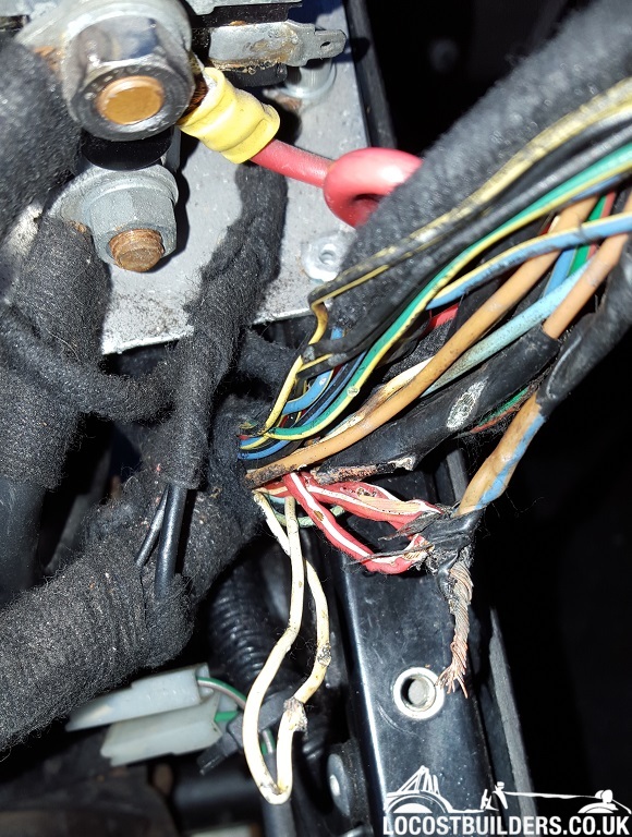
This is after unwrapping part of my loom (not made by me) - almost missed a section of cloth tape that appeared to be brown (the twisted together
wires) rather than black.
The white wire loop as you look bottom centre in the photo, is the signal wire for the speedo. It was stuck to the other wires. I need to replace that
entire section of wiring now I think! Nightmare.
|
|
|
perksy
|
| posted on 3/2/16 at 07:44 PM |
|
|
Yep, That'll do it 
At least you've caught it before it got a whole lot worse
|
|
|
02GF74
|
| posted on 3/2/16 at 09:55 PM |
|
|
Nasty but at least it appears the source of the problem has been identified.
Vehicle Wiring Products sell coloured wired with tracer should you wish to match the existing loom. It may turn out to be a pretty big job if you
want to do it properly i.e. peel back the loom cover and replace the full cable runs from end to end.
A cheaper and quicker job is to peel back about 15-20 mm of insulation, push the copper wire ends into each other and twist before soldering followed
by heatshrink (that you will ofcourse have fitted before soldering the wires together!). I suspect you may not have enough slack in the cables to do
this.
|
|
|
james h
|
| posted on 4/2/16 at 08:03 AM |
|
|
I want to fix it properly for sure. However, the car is in a rented garage with no tea-making facilities, and less importantly, no electricity for a
soldering iron.
I'm at uni at the moment, so what I might have to do is take the loom out of the car and replace the damaged wiring away from the car.
Fortunately I have a large selection of coloured wires from VWP (I bought some to move switches around).
Do I fix the wires by soldering in new sections, or with crimping in connectors? Proper ones like these:

|
|
|
ian locostzx9rc2
|
| posted on 4/2/16 at 08:15 AM |
|
|
Cut the loom back a bit to make sure there's no damage further back as for soldering or connectors either will be ok as long as it's
nicely insulated.
|
|
|
02GF74
|
| posted on 4/2/16 at 09:22 AM |
|
|
quote:
Originally posted by james h
. However, the car is in a rented garage with no tea-making facilities, and less importantly, no electricity for a soldering iron.
Tea = solved by vacuum flask or gas camping stove
Soldering iron = gas or battery powered, search on maplins or ebay, the one that runs off AA batteries is appealing, almost instant heat.
Repair in situ shoukd be qicker and youll know you have added the correct amount of wire.
|
|
|
james h
|
| posted on 6/2/16 at 06:50 PM |
|
|
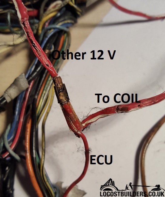
I want to repair a section of wiring from the ECU/ICU which splits to the coils and another 12V wire.
The gauge of wire increases where it splits to the (above mentioned) two slightly thicker sections - these thicker sections have been repaired poorly
in the past and need redoing, which is what I'm attempting now.
I already have the same gauge and coloured wire as the Yamaha OEM one coming from the ECU.
If the Yamaha wire is fine for the ECU/ICU, then surely such a gauge will be fine for the other two wires joined to it too?
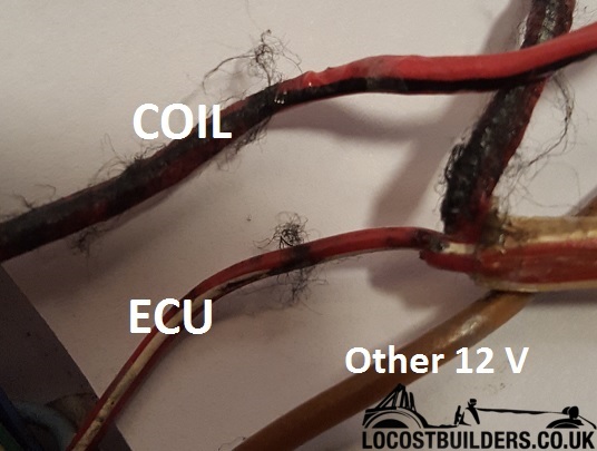
Here is the split:
Here is the difference in gauge of wire:
|
|
|
CosKev3
|
| posted on 6/2/16 at 08:32 PM |
|
|
Nice to see you've found the issue
the coils will need a thicker wire than the ECU,I would replace like for like.
|
|
|
gremlin1234
|
| posted on 6/2/16 at 08:40 PM |
|
|
quote:
Originally posted by CosKev3
Nice to see you've found the issue
the coils will need a thicker wire than the ECU,I would replace like for like.
certainly don't replace the failed wires with anything
less
the wire to the ecu may be just an input (but wiring theory says it should be as thick as the others unless explicitly fused)
you appear to have a brown/light-blue wire connected to red/white, - why?
|
|
|
james h
|
| posted on 6/2/16 at 08:43 PM |
|
|
quote:
Originally posted by CosKev3
Nice to see you've found the issue
the coils will need a thicker wire than the ECU,I would replace like for like.
Yep, should be able to update you on the 5JJ clocks soon! (I hope).
I think you're right regarding the wires, like for like is going to be best. It's annoying as I have the right colour wire too!
|
|
|
CosKev3
|
| posted on 6/2/16 at 08:46 PM |
|
|
I'm pretty sure that red and white wiring with the take off to ECU is standard Yamaha wiring?
The brown and blue looks like that's been used when car built to give the red/white wire it's ignition feed?
|
|
|
britishtrident
|
| posted on 6/2/16 at 08:57 PM |
|
|
Coil peak current during dwell phase ramps up from 0 to 12 amps over about 2,5 to 3.5ms for wasted spark system, the duty cycle is generally quoted
as about 30 to 35% at 7,000 rpm
[img]
 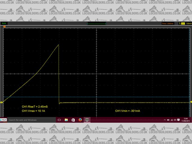
K series Double Cop Primary
[/img]
[Edited on 6/2/16 by britishtrident]
[I] What use our work, Bennet, if we cannot care for those we love? .
― From BBC TV/Amazon's Ripper Street.
[/I]
|
|
|
james h
|
| posted on 6/2/16 at 10:09 PM |
|
|
quote:
Originally posted by CosKev3
I'm pretty sure that red and white wiring with the take off to ECU is standard Yamaha wiring?
The brown and blue looks like that's been used when car built to give the red/white wire it's ignition feed?
Looking at the wiring diagram in the back of the Haynes, I think you are probably correct.
quote:
Originally posted by britishtrident
Coil peak current during dwell phase ramps up from 0 to 12 amps over about 2,5 to 3.5ms for wasted spark system, the duty cycle is generally quoted
as about 30 to 35% at 7,000 rpm
[img]
K series Double Cop Primary
[/img]
[Edited on 6/2/16 by britishtrident]
And I think I need to get one of those scopes! Some good info there, thanks.
[Edited on 6/2/16 by james h]
|
|
|