lsdweb
|
| posted on 28/11/07 at 08:11 PM |

|
|
Pull up resistor?
Hi All
I'm wiring in my DL1 data logger and trying to work out the wiring for the oil temperature and pressure sensors.
The manual says
When supplied with a cable for use with the Data Logging Units, the sensor is supplied with a series 1k "pull up" resistor. There are 3
leads that come from the sensor: the red lead should be attached to the +5v supply from the Data Logger Unit, the black lead should be connected to
the ground connection and the white lead should be connected to an analogue input.
I'm a bit confused on where the pull up resistor sits and how they use a three wire cable on a two terminal sensor (is one the screen?)
I'm not using their cable or sensors - have a look at their prices !!
Any thoughts?
Wyn
|
|
|
|
|
MikeRJ
|
| posted on 28/11/07 at 08:24 PM |
|
|
The 1k resistor will be inserted somewhere in the red wire. Three wires are used because you have to supply a current to the sensor via the pullup
resistor in order to get a voltage to measure. The voltage is measured via the white cable connected to the analog input of the datalogger, and
eveerything is referenced to the ground connection. Essentialy the red and white wires will be joined togther at one terminal of the sensor.
In practice you should be able to connect the pull-up resistor between the +5v supply and the analog input at the datalogger itself, so you would then
only need two wires going to the sensor.
|
|
|
lsdweb
|
| posted on 28/11/07 at 08:40 PM |
|
|
Thanks Mike
Any chance of one of your great diagrams.....
|
|
|
tegwin
|
| posted on 28/11/07 at 10:17 PM |
|
|
Mike RJ- Im not convinced you are correct...
Logic would suggest that "pull up" resistor should go on the white cable so that the analogue input to the module is not allowed to
"float" (And is, by deffinition, pulled "high" when it is not being signaled to reduce spurious results...)
I may be wrong though...these things happen...
|
|
|
Bob C
|
| posted on 28/11/07 at 10:18 PM |
|
|
I'd say between red wire and white wire....
best of luck ;^)
Bob
|
|
|
MikeRJ
|
| posted on 28/11/07 at 11:10 PM |
|
|
quote:
Originally posted by tegwin
Mike RJ- Im not convinced you are correct...
Logic would suggest that "pull up" resistor should go on the white cable so that the analogue input to the module is not allowed to
"float" (And is, by deffinition, pulled "high" when it is not being signaled to reduce spurious results...)
I may be wrong though...these things happen...
Correct, the resistor does connect to the white wire as I said, and is also connected to the red wire which provides the pull-up.
The sensor is resistive and the datalogger measures voltage. The simplest way to convert resistance to voltage is to put the variable resistor in one
side of a potential divider, the other half is formed by the "pull-up" resistor.
Sorry for ultra crappy ASCII art, the forum is horribly broken so it eats back slashes and the code tags double space everything.
+------1k Resistor-------o +5v
|
+----------------------------o Datalogger Input
|
#
#
# Sensor
#
|
|
+----------------------------o 0v
|
|
|
lsdweb
|
| posted on 29/11/07 at 08:47 AM |
|
|
Like this?
 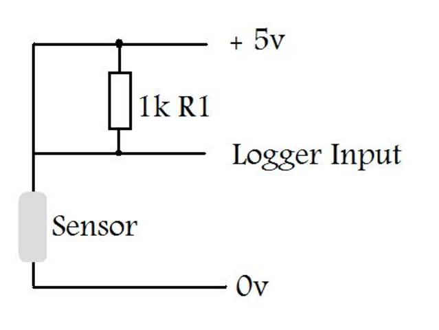
Rescued attachment logger2.jpg
|
|
|
MikeRJ
|
| posted on 29/11/07 at 09:45 AM |
|
|
Not quite! In that schematic the 1k resistor is rather redundant as it has both sides connected to +5v, so the datalogger would only ever see +5v
irrespective of the sensor resistance.
By the power of MS Paint I have corrected it 
 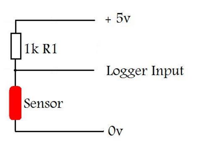
Logger-sensor connection
|
|
|
lsdweb
|
| posted on 29/11/07 at 01:43 PM |
|
|
Thanks Mike
It's obvious now!!!
Regards
Wyn
|
|
|
omega0684
|
| posted on 16/4/11 at 04:07 PM |
|
|
can anyone post up a diagram of how to wire up the fuel sender please?
I love Pinto's, even if i did get mine from P&O!
|
|
|
daniel mason
|
| posted on 20/4/11 at 08:54 PM |
|
|
as far as im aware alex the fuel sender wire from the dash connects directly to the wire through the sender to ground. then before you actually
connect the wires together you need to take a resistance reading across the sender with tank empty,half full,full and enter these when programming the
dash!
i am currently trying to set up the can lo and high from my dta s60 to transmit data direct from ecu to dash, as the ecu monitors loads as
standard,meaning less wiring
|
|
|