reservoir cogs
|
| posted on 7/1/11 at 07:41 PM |

|
|
bottom rail cut dimensions vs plan dimensions
Hi all, I recently got hold of a copy of the haynes roadster and have just started building a CAD model. Starting with the bottom rails ive modelled
them as per drawings in the appendix but when assembling them together there are several rails that pass through each other, checking the lengths
against the plan dimensions in chapter 1 it seems the cut dimensions do not directly translate.
What is the purpose of this and what dimensions should i be following?
|
|
|
|
|
handyandy
|
| posted on 7/1/11 at 08:04 PM |
|
|
I,m not a CAD operator so can,t comment why CAD seems to struggle computing the dimensions but when actually building the chassis in steel, the
dimensions in the book are spot on, tho there have been a few revised dimensions from the books first edition, tho they are mainly to do with the
length of the wishbones , there is one small dimension fault, namely the SW parts, SW1 needs a 19degree compound angle & not 23 as stated in the
book.
Just a thought & I maybe wrong but maybe CAD can,t take into account the rounded profile of steel?? .
Sorry if that doesn,t help you tho 
cheers
andy
|
|
|
reservoir cogs
|
| posted on 7/1/11 at 09:14 PM |
|
|
quote:
Originally posted by handyandy
I,m not a CAD operator so can,t comment why CAD seems to struggle computing the dimensions but when actually building the chassis in steel, the
dimensions in the book are spot on, tho there have been a few revised dimensions from the books first edition, tho they are mainly to do with the
length of the wishbones , there is one small dimension fault, namely the SW parts, SW1 needs a 19degree compound angle & not 23 as stated in the
book.
Just a thought & I maybe wrong but maybe CAD can,t take into account the rounded profile of steel?? .
Sorry if that doesn,t help you tho
cheers
andy
Hi Andy, I can make the steel sections fit but looking at the dimensions in the book from a mathematical point of view it seems they dont directly
relate to each other which is why the CAD assembly doesnt seem to work. I can make them fit but that involves changing the dimensions & angles of
the sections to match the layout shown in chapter 4. Doing this however means that whole numbers cannot be used for the cutouts and the dimensions
change a slight amount, for example BR3&4 would change from 584 to 584.4 and the angles from 10 to 9.62 deg at either end if they were to match
drawing specs on chapter 4. Using these dimensions i can get the projected distance to match the book as shown below:
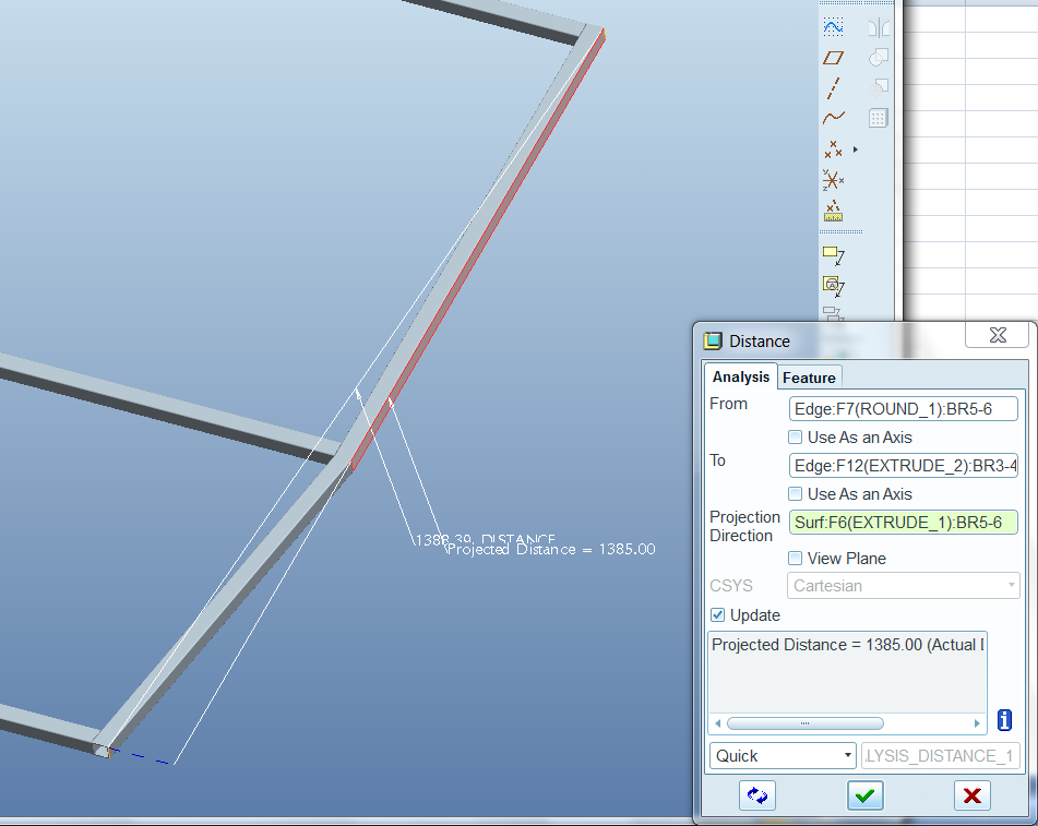
If i use the standard dimensions the projected distance is 1388.13.

I can see why theyve possibly done this as it means your not trying to cut steel sections to a decimal point but over the project length that adds up
to a 3mm increase over the drawing.
[Edited on 7/1/11 by reservoir cogs]
[Edited on 7/1/11 by reservoir cogs]
|
|
|
handyandy
|
| posted on 7/1/11 at 09:21 PM |
|
|
I,m just doing some calculations, will get back to in a few mins.
It,ll be interesting see if we can work out whats happening, tho I have heard in the past that CAD doesn,t like working beyond 0.1 when it has to
allow for angles, not sure how true that is tho .
cheers
andy
|
|
|
reservoir cogs
|
| posted on 7/1/11 at 09:23 PM |
|
|
quote:
Originally posted by handyandy
I,m just doing some calculations, will get back to in a few mins.
It,ll be interesting see if we can work out whats happening, tho I have heard in the past that CAD doesn,t like working beyond 0.1 when it has to
allow for angles, not sure how true that is tho .
cheers
andy
Ive just made some small alterations to my post as i typed the wrong number for BR3 length its been amended now, ive done the calcs both on paper and
in CAD and they come out to be identical
|
|
|
Mad Dave
|
| posted on 7/1/11 at 09:28 PM |
|
|
The dimensions in the book are to zero decimal places. You are never going to be able to create a CAD model by assembling individual tubes. The best
way by far is to create a weldment which is a single part file made up of individual bodies which are dimensioned as per the chapters.
I can assure you that the CAD drawings are correct
|
|
|
handyandy
|
| posted on 7/1/11 at 09:36 PM |
|
|
As I,ve already said, I,m not a CAD user so don,t really know its limitations,
BUT......
here,s me thinking from "top of my head"  
Instead of using the dimensions of the bottom rails , as in your sketch above , you have BR5 as 813mm & BR3 as 584mm which is as per book
dimensions.......
here,s my suggestion for seeing if you can get CAD to "understand" the measurements/angles...............
how about putting in the total chassis bottom rail dimension in as 2360mm which is the total distance between the rearward face of BR12 to the forward
face of FF1, which would create the outer perimeter of the chassis & see if CAD will then work out the dimensions that it can accept once putting
in the some angles (eg 10degree,s of BR3 & 4, & the 16degree,s of BR1 & 2 ) & seeing if it will work that way......again, I don,t know
if it will but setting the outer parameters of the chassis into the CAD drawing & see what happens.......just a thought 
I,ve cut over 40 chassis,s for the Roadster & have not had a problem with the bottom rails when fabricating it in steel, CAD is not something I
know much about ( read.....zilch  ). ).
cheers
andy
|
|
|
reservoir cogs
|
| posted on 7/1/11 at 10:47 PM |
|
|
quote:
Originally posted by Mad Dave
The dimensions in the book are to zero decimal places. You are never going to be able to create a CAD model by assembling individual tubes. The best
way by far is to create a weldment which is a single part file made up of individual bodies which are dimensioned as per the chapters.
I can assure you that the CAD drawings are correct
Hi Dave, it shouldnt be a problem to build a CAD model through an assembly, ill just have to work off the scheme drawings to get the exact dimensions
for section length and angles. Id rather follow this method as it will means the sections length will then exactly match scheme dimensions.
quote:
As I,ve already said, I,m not a CAD user so don,t really know its limitations, BUT...... here,s me thinking from "top of my head" Instead
of using the dimensions of the bottom rails , as in your sketch above , you have BR5 as 813mm & BR3 as 584mm which is as per book
dimensions....... here,s my suggestion for seeing if you can get CAD to "understand" the measurements/angles............... how about
putting in the total chassis bottom rail dimension in as 2360mm which is the total distance between the rearward face of BR12 to the forward face of
FF1, which would create the outer perimeter of the chassis & see if CAD will then work out the dimensions that it can accept once putting in the
some angles (eg 10degree,s of BR3 & 4, & the 16degree,s of BR1 & 2 ) & seeing if it will work that way......again, I don,t know if it
will but setting the outer parameters of the chassis into the CAD drawing & see what happens.......just a thought I,ve cut over 40 chassis,s for
the Roadster & have not had a problem with the bottom rails when fabricating it in steel, CAD is not something I know much about ( read.....zilch
). cheers andy
Andy ive no doubt the chassis will go together off the specifications in the book, my only doubt is that the finished chassis wont theoretically match
the drawing specs. In a real world i know this wont be the case anyway due to machining tolerances and distortion, and also that it will have a
negligible effect on vehicle dynamics but i guess i just like to be fussy
Following what you said here are the results:
As you can see drawing the bottom rails as per scheme gives the dimensions for BR3&4 as i stated above:
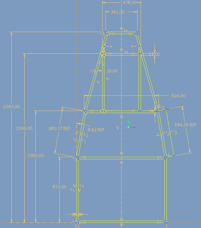
Though the difference in length and angle of both BR3-4 & BR8-9 are small taken over the total length of chassis section the difference adds up to
the following.
Drawing the model again but this time using the cut section dimensions from the appendix the following occurs:
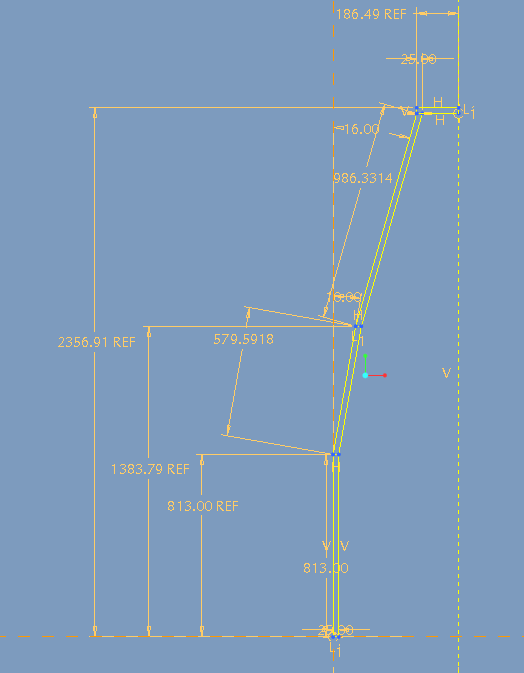
This leaves the chassis 3.1mm shorter in total length, and 19mm shorter in width at the top section. Like i said the difference is largely negligible,
and taking into account a general angular tolerance of 2.5 deg and linear tolerance of 2mm for each section the end result will be far from that
anyway. Im just thinking that if I can get access to relatively high precision machine tools it would be better to work to the nominal dimensions.
|
|
|
ashg
|
| posted on 8/1/11 at 12:43 AM |
|
|
i had a chat with chris about this about 2 years ago when i built my car. when he wrote the book he purposely decided not to go to 0.1mm etc as it
was decided that the average home builder wouldn't be able to achieve that level of accuracy especially on the compound joints. if your going
to cut the box on a tube laser i know of a man that may have a digital cut list.
to be honest it would be overkill to go to an accuracy of more than half a millimetre.
Anything With Tits or Wheels Will cost you MONEY!!
Haynes Roadster (Finished)
Exocet (Finished & Sold)
New Project (Started)
|
|
|
PSpirine
|
| posted on 8/1/11 at 09:50 AM |
|
|
I've CAD'd the thing in solidworks (not finished yet, but about 60%) and I struggled at first too, but then got it all spot on (except
where I purposefully changed the design) to within 1 decimal place. As said, there will be differences of 0.1mm etc. which are irrelevant.
|
|
|
Steve Hignett
|
| posted on 8/1/11 at 10:00 AM |
|
|
Hi,
Just out of interest - is there a reason why you're spending so long thinking/discussing/deliberating/drawing instead of just making it?
|
|
|
Mad Dave
|
| posted on 8/1/11 at 10:35 AM |
|
|
There is no need to model the Roadster unless you plan to modify it
The original book models and drawings were done in Solidworks so are accurate. It is pointless trying to get dimensions to 0.1mm because how are you
going to achieve that with a bandsaw? Anyway it's not a bad thing to have a slight gap between tubes when welding. Just make sure you
accurately mark out the chassis base on your build table
 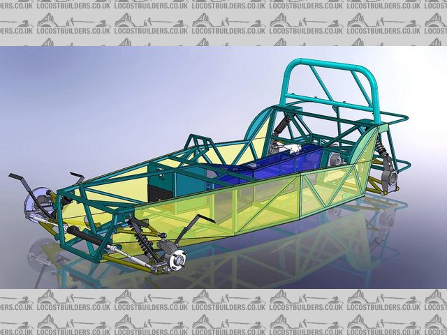
Haynes Roadster CAD iso a
Haynes Roadster CAD iso b
[Edited on 8/1/11 by Mad Dave]
|
|
|
architect
|
| posted on 1/3/11 at 01:24 PM |
|
|
@reservoir cogs,
I modeled the bottom chassis rail components in sketchup and am getting similar discrepancies, too. I also calculated the angles manually and arrived
at the same deviations. I was wondering what approach you used in resolving the issue (if you ever did) - if you altered the angles of the B3 and B4
rails, modified their dimensions instead, or re-positioned BR10.
Since per forum postings, the dimensions in the book has been determined to be correct, I am really perplexed by the discrepancies cropping up since
all the values are zero decimal point and hence are not subject to precision rounding, if any at all. Moreover, the same deviations came up when I
manually calculated the positions, independent of sketchup or any CAD program.
Is it possible that during the actual build, adjustments were made to rectify the discrepancies? After all the values concerned are very minimal
relative to the overall dimensions. The way I see it, though I might be 100% wrong, it would be easy to pull BR3 and BR4 outward to accommodate BR10
at its intended position.
Anyways, reason why I am modeling the chassis first is that I plan to modify it and expand the width and other dimensions accordingly. Also, being an
architect, I guess I am used to working off CAD drawings and have been conditioned to be bothered by both design and structural issues, however minor
they may be.
TIA.
|
|
|
Bare
|
| posted on 1/3/11 at 06:11 PM |
|
|
cad
CAD really does have it's limitations :-)
It fools us into assuming that whats' 'on screen' is what you will actually be welding together.. As if
This isn't Boeing kids, there's ...no.. direct to robotised fabrication possibilities Here :-)
To build this thing you will need to pencil out the frame outline onto a build table, then build the thing, piece by piece, just like those Model
Airplanes' one built as a kid.
Any 'CAD' errors will be looong forgotten, as new and improved errors will surface.
Even a hacksaw cut cannot be 'that' precise.
I'd be far more concerned with 'fixin' the load paths from "Ron's" errm .. odd, suspension bracket mounting
/design/locations than the ultimate length of a tube... which will invariably (if Human:-) get cut a mm or so 'inaccurately'.
[Edited on 1/3/11 by Bare]
|
|
|
architect
|
| posted on 2/3/11 at 01:26 AM |
|
|
@Bare,
While I acknowledge CAD has its limitations, what bothers me is that if you manually draw out the lay-out, the angles are off. And if you manually
calculate the angles pertinent to the dimensions or vice-versa, they are also off. Reservoir cogs got similar errors and in fact has posted them here.
Thus the discrepancy has nothing to do with CAD and its so-called limitations.
I submit I am a complete noob when it comes to car building, and perhaps such discrepancy is well-accepted since this can be corrected during the
actual build. It is just that I am more used to nitpicking details in architectural/construction CAD drawings since such oversights and/or errors can
result in disastrous results post-construction.
|
|
|
PSpirine
|
| posted on 2/3/11 at 01:54 AM |
|
|
Are you sure you're measuring your BR3/4 and 8/9 correctly? The length of 584mm is the overall maximum length of the steel section, if you only
look at one side of the box section it'll be less than that (by 10 degrees over 25mm, whatever that is).
I have a feeling your file shows the reference dimension of the outer side of BR3/4.
Check your diagonals as per the book schematic, if they're within 0.5mm, then you're fine.
|
|
|
architect
|
| posted on 2/3/11 at 04:09 AM |
|
|
@PSpirine,
Thanks for the reply.
Yes. Each side of the BR3/4 is 584mm, and the resultant side where I applied the 10 degrees is 25.4mm x 25mm.
I have not tried to place the BR8/9 bars yet.
BR
|
|
|
architect
|
| posted on 5/3/11 at 08:49 AM |
|
|
Finally found the answer in the Haynes forum. Not sure if I am allowed to post a link but it is in the chassis subforum under the "the haynes
chassis design. Per user eSteve,
quote:
We basically have two sets of information enabling us to build the lower chassis, that given in fig 4.2 and that given in the cutting list by way of
the dimensions of the bottom rails. Either could be used to construct the bottom rails, but the correct one is fig 4.2 as stated by Chris Gibbs (see
below) and for the reason I give above i.e the limit on the tolerances of the cutting list, to the nearest degree and millimetre.
Remember to keep a foot in the real world whilst modelling. Think about construction. The dimensions given in fig 4.2 are the important ones and what
a welder would use to build the chassis rails, in fact all the lower chassis could be built from the dimension given in fig 4.2. Without using the
cutting list for the lower rails! This is why Chris Gibbs states that fig 4.2 is used to layout the chassis and tubes are cut to the correct length to
fit, (note: not necessarily cut to the cutting list lengths and angles).
I hope this helps those who, like me, are a bit confused about the dimensions.
|
|
|