
front lower balljoint dimensions/offsets
davimora - 24/10/18 at 08:07 AM
hi,
the suspension drawings in my hands just define the distance between balljoint's center and the rosejont's hole center.
online i wasnt able to find the exact distance between the bj's center and the horizontal hole center (or another reference point, as the
vertical hole).
anybody know this magic number?
See image
thanks!
David
[Edited on 24/10/18 by davimora]
jps - 24/10/18 at 08:28 AM
What are you building - and what suspension plans? Doesn't look at all like the Haynes (which I assume is fairly similar to the Locost)...?
And what ball joint are you using? I thought everyone used a Maxi ball joint - which doesn't look like that...
davimora - 24/10/18 at 08:41 AM
hi Jps,
i'm building a Midlana, i'm using a balljoint is MX5 NB (made from MAPCO in this case but doesnt really matter).
i posted my question on the mx5 sub-forum, maybe somebody know this little number.
thanks!
jps - 24/10/18 at 09:16 AM
quote:
Originally posted by davimora
hi Jps,
i'm building a Midlana, i'm using a balljoint is MX5 NB (made from MAPCO in this case but doesnt really matter).
i posted my question on the mx5 sub-forum, maybe somebody know this little number.
thanks!
Might be worth looking on the Haynes Roadster site too (http://forums.haynes.co.uk/index.php) - plenty of MX-5 builds there - so presumably the same
sort of front upright solutions?
nick205 - 24/10/18 at 09:19 AM
Don't know the ball joint, but also wonder what you need that dimension for?
If you have a ruler you must be able to measure it near enough across the base of the ball joint (looking at the image).
davimora - 24/10/18 at 10:21 AM
i need this information because, i have this equation: rosejoint + tube + bj carrier + bj offset = have to be X mm.
i have 2 missing variables, tube length (and it's ok) and bj offset (what i'm trying to find out).
measure it manually, yes, is possible and i did it better as i can. the real shape is not so easy to measure.
if i can find the 'official' distance, i can sleep better)
it's my first car and.. probably i'm too worry about nothing.
nick205 - 24/10/18 at 10:45 AM
Understand your problem now.
I'd have thought ±2mm is acceptable in this case.
If you've not already made the upper wishbones then make the upper outer ball joint adjustable so you can set the camber of the wheel.
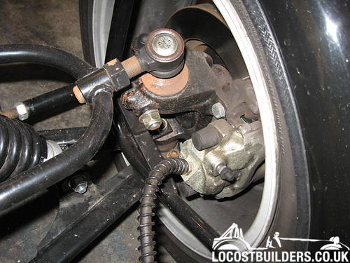
This photo shows the front upper outer ball joint on the MK Indy I built. The ball joint itself is a Transit drag link and it screws in/out of the
wishbone giving this adjustment...
[Edited on 24/10/18 by nick205]
jonny007 - 24/10/18 at 11:06 AM
There are some mx5 suspension drawings on Grabcad, if you search for Miata, you may be able to measure from there
davimora - 24/10/18 at 11:20 AM
@jonny007
i think i have this 3d model. as i remember there was some problems about dimensions. i will give another try.
@nick205
all the wishbones are fully adjustable by design. so i can get 'close enough' with measurements and adjust it later, as you said)
thanks!
Camber Dave - 24/10/18 at 12:04 PM
As per your drawing - 28.61mm (1.1/8"
The centre of the ball is 5mm below the circlip groove
Displace the stud fully one way and sketch a pencil C/Line on the casting
Move it all the way back and repeat a line
Where they cross - Ball centre.
From the cross bolt to the vertical one is 47.6mm (1 7/8"
The included angle between ball stud and base plate is 70 deg.
Edited to correct dimension Some Japanese stuff is Imperial.
[Edited on 24/10/18 by Camber Dave]
davimora - 24/10/18 at 12:36 PM
ooooh!! thank you very very much Dave!!
now i will sleep better)
i wonder.. where you found this informations? any link to this (and maybe others) valuable informations?
Camber Dave - 24/10/18 at 03:04 PM
I built a a Haynes using MX5 uprights and pushrod suspension
So had my drawings on file and a spare joint to check with.