
Haynes Roadster MX-5 scratch build
Half Finished - 1/9/18 at 12:09 PM
Hello everyone, I have been working on this for a while now. I thought I would share my progress so far.
This will use as much of the donor car as possible to keep the budget low. I am planning to use a Speeduino ECU. I am hoping to make/fabricate as much
as possible of everything else. I am using the Saturn chassis plans.
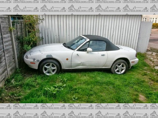
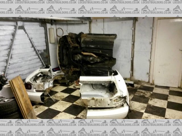
I managed to pick up this sorry looking donor car as an MOT failure for practically nothing. I stripped it down for everything I needed and sold
everything else. I managed to make enough money to buy the box section for the chassis later on.

Description

Description
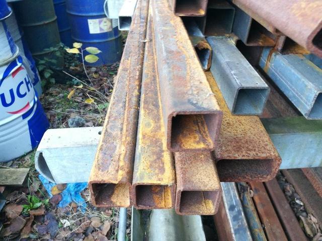
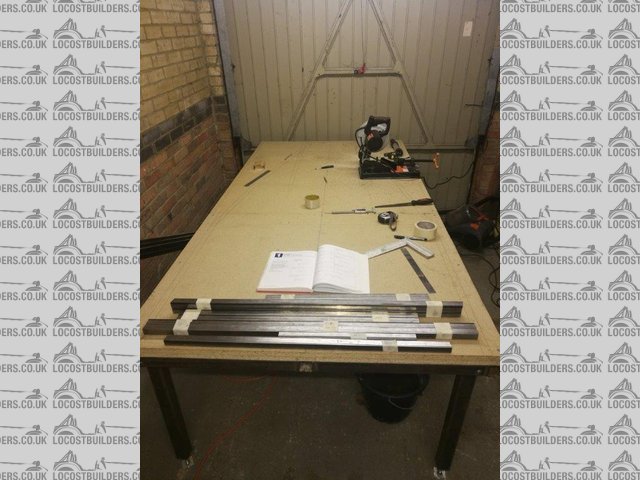
I weighed in the battery and picked up some scrap box section steel for my build table.

Description

Description
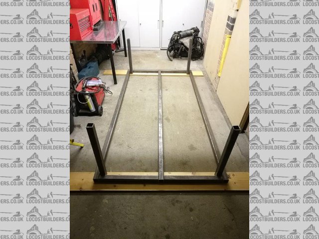
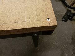
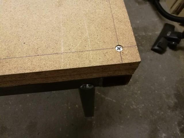
The legs are bolted on with coach bolts. I'm hoping to store it if I decide to build a second one later on.
The top surface is just 6 pieces of chip board fixed with sheet metal screws. The build table is made from all scrap and cost me nothing in materials.
Description
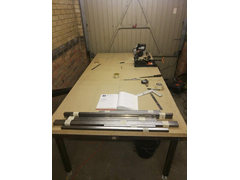
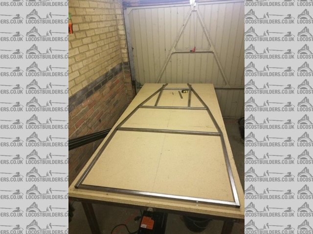
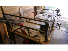
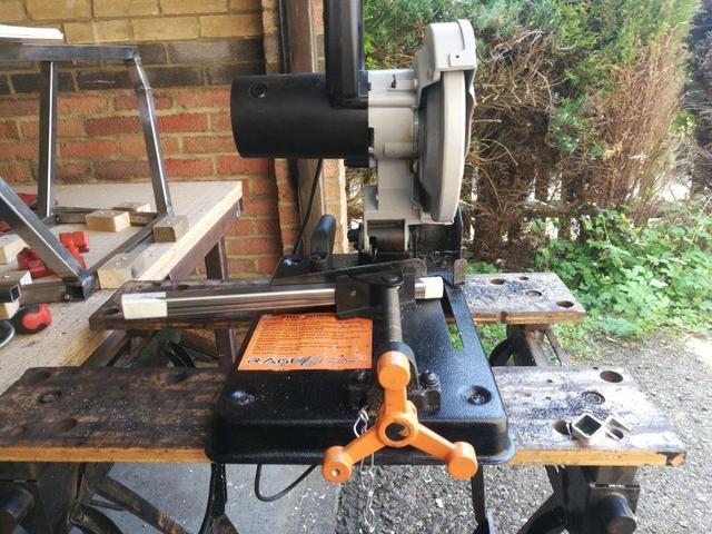
After marking out the chassis dimensions I cut the base rails to length with an evolution chop saw. It makes a nice cut and needs minimal deburring
with a file.
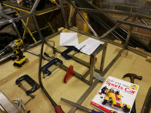
Description
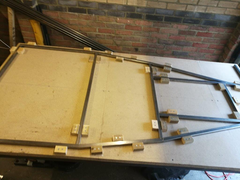
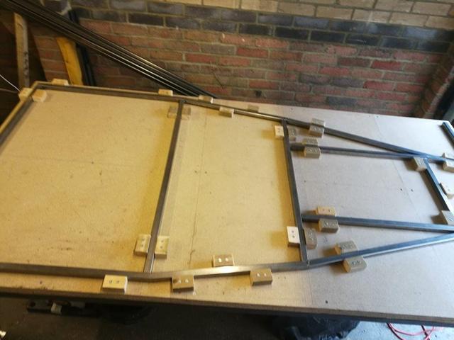
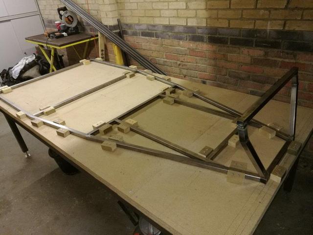
Laying out the base rails and securing with wooden blocks.

Description
Description
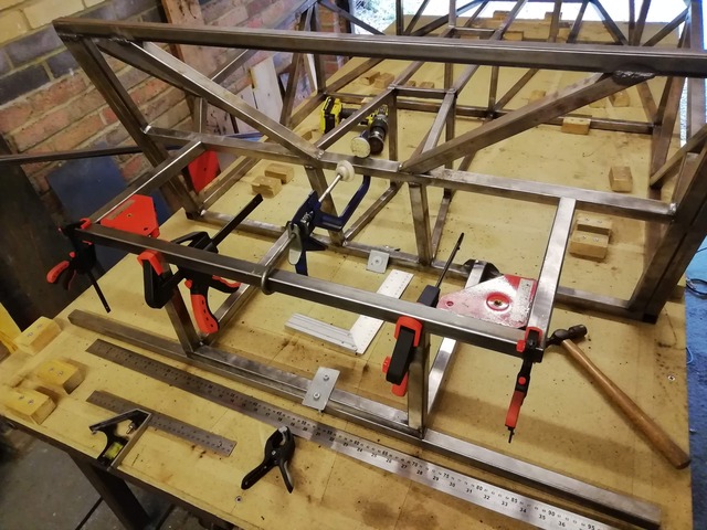
Jig for the front frame
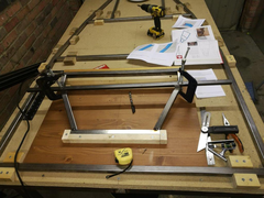
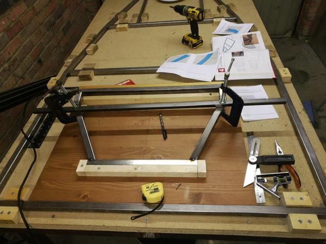
Description
Front frame welded

Description
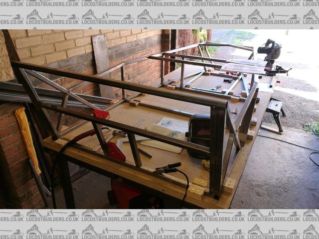
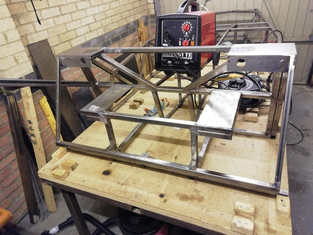
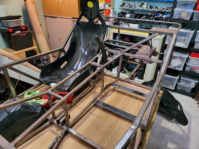
Front uprights in place. I know the driver side upright rail is in the wrong place. I moved it later on.

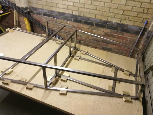
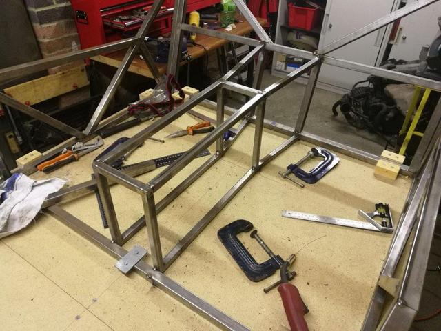
Description
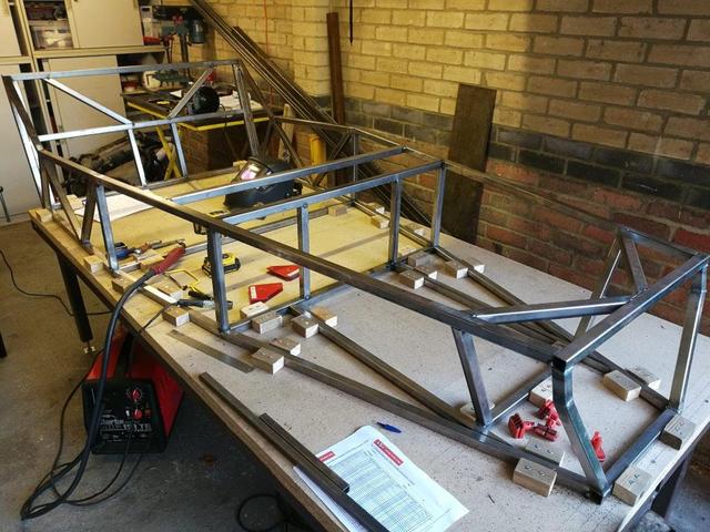
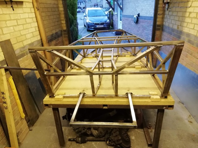
Rest of the uprights in place

Description
Description
Seat back rails in place

Description
Cutting the transmission tunnel rails. Some of these had angles on both sides, I clamped them into the chop saw with an angle to the base.

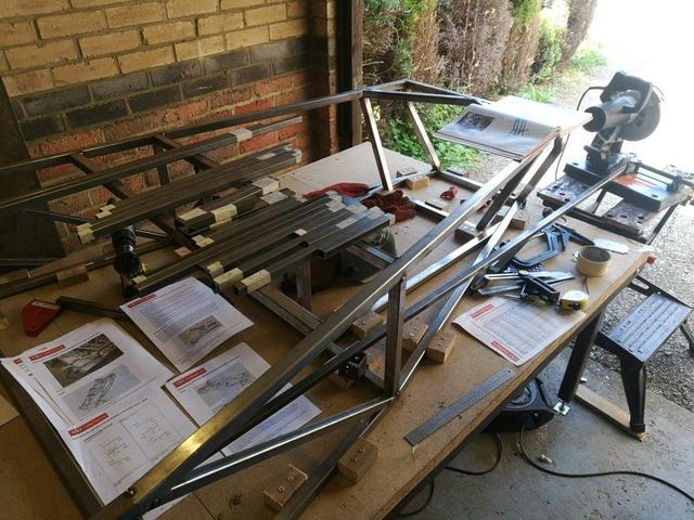
Description

Description
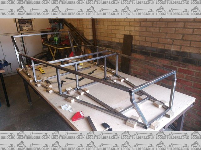
Setting out the transmission tunnel

Description

Description
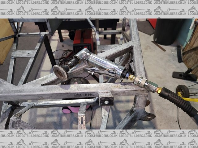
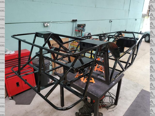
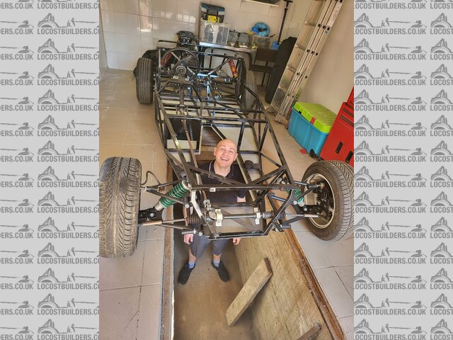
And this is my progress up to today. I've been away all summer and annoyingly the chassis has a light coating of surface rust.


Description
Getting there slowly. The next step is to fully weld the chassis and cut the bars for the rear.
It is handy there is metal scrapyard next door that always has a big stockpile of aluminium and steel too.
ianhurley20 - 1/9/18 at 12:38 PM
Welcome to the group . Great progress. The light rust can often be cured with a dab of phosphoric acid which converts the rust to a black phosphate.
Costs about Ł8 for a bottle from ebay. I used the wiring loom and ecu from the MX5 with mine and also used brake pedals and steering column as well so
all the column switches etc.
Good luck and feel free to ask questions, someone will know the answer
Half Finished - 1/9/18 at 12:59 PM
Thank you. I will get some of that.
I didn't think of pedals, I'm not sure I kept them.
I stripped the car down ages ago before moving. The bits have been sat in a shed. It should be interesting to refurbish everything, the MX5 was on
180,000 miles!
The cost of a brake seal kit is almost as much as a whole refurbished caliper.
Slimy38 - 1/9/18 at 01:21 PM
quote:
Originally posted by Half Finished
The cost of a brake seal kit is almost as much as a whole refurbished caliper.
I got my seals from Brakes International on Ebay, it cost me Ł15 for the rears, Ł14 for the fronts and another fiver for new brake nipples. The
pistons were salvageable as were the handbrake mechanisms (once they'd sat in rust remover to get them open in the first place!!).
It was surprisingly satisfying to clean and recondition them myself though, I now have these waiting to go on the car;

Half Finished - 1/9/18 at 03:35 PM
They look really smart. I'll have a go with my calipers.
Half Finished - 12/4/20 at 08:57 PM
How long ago did I start this thread?! I have been making some progress again on this.
Cut the brackets from box section offcuts

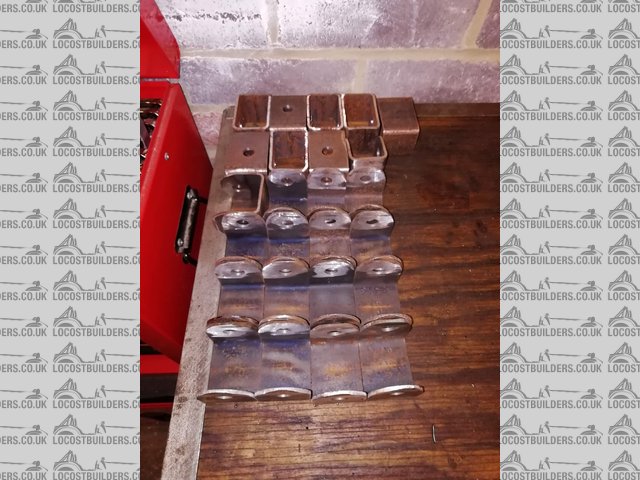
Description
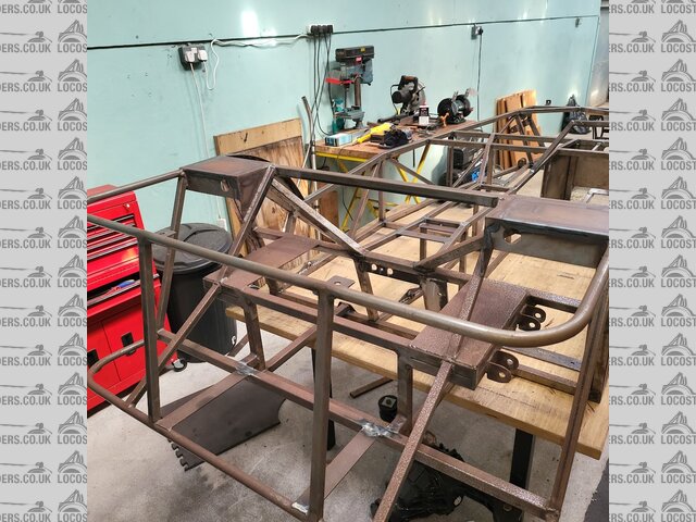
Started adding the rear bars. got this part jigged up and fully welded.

Description
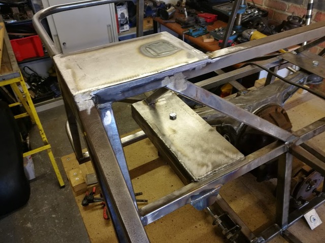
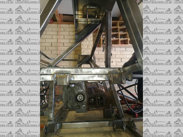
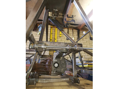
Adding the wider section to accommodate the MX5 diff from the Saturn plans.

Description
More plates added.

Description
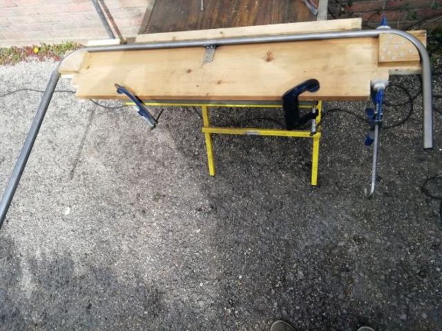
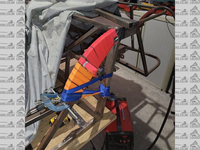
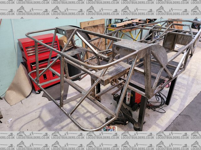
For the rear panel supports I made up a former. Clamped everything down and bent the two ends round with a bar.
Worked a treat. Even got the wife to help.

Description
And tacked in. The saturn plans don't have these but I'm going with the the aluminium bodywork.

Description
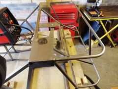
Even got my son helping out

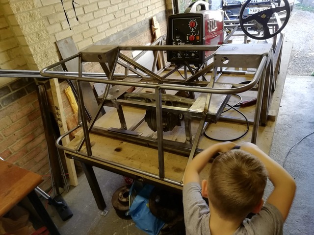
Description
Next job wishbones. Parts arrived from thelatheman on ebay.
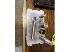
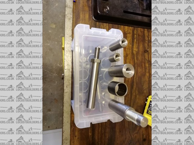
Description
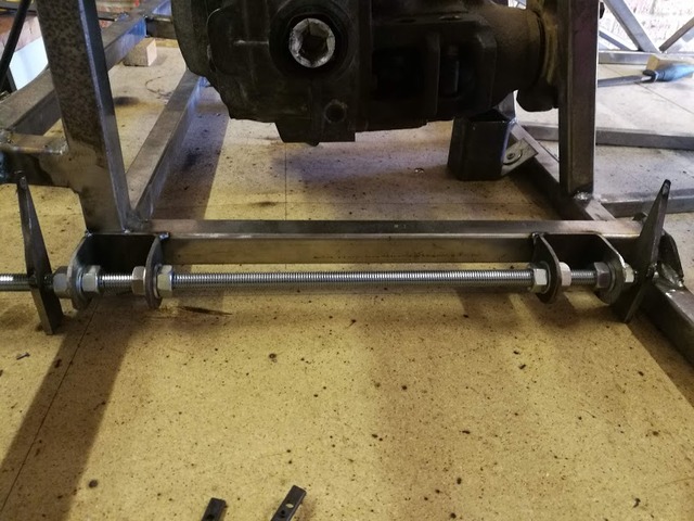
I've also been looking at the best way to mount the diff. I will make up a nose mount bracket and polybush the top mounts.
I was sorting through the donor parts. It seems my drive shafts are properly stuck in the hubs. they are currently sitting up right with penetrating
oil in the cup, hopefully they free up.
Half Finished - 13/4/20 at 09:33 AM
What clearance is best for the sump on these? Im using the MK2 1.8. I would prefer to not have the sump below the chassis rails.
Can I shorten the sump to the same height as the gearbox bellhousing and mount level?
ianhurley20 - 13/4/20 at 10:56 AM
I didn't shorten the sump on mine and ended up with 90mm clearance under the sump and 5 mm clearance under the Equinox bonnet. If yours is a VVTI
engine I guess a bit of a bulge will be needed.
Half Finished - 25/4/20 at 05:54 PM
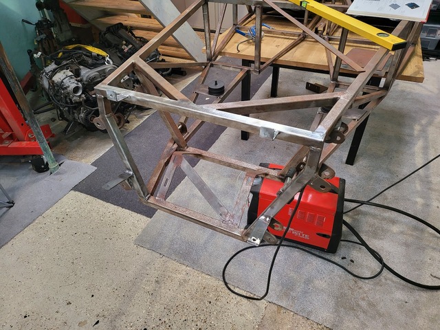
Got a bit more done on this today. Welded up the rear section and grinded down the top plates.

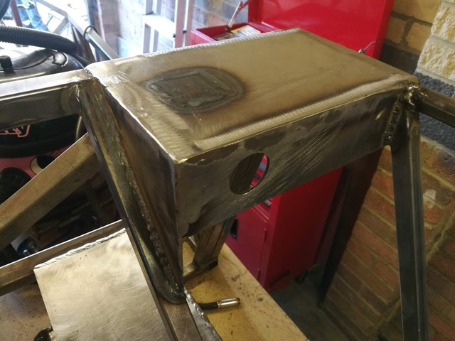
Description
Still need to weld the underside but happy with how this turned out.

Description
Tacked in the lower brackets

Description
and the top brackets

Description
And then welded both sides

Description
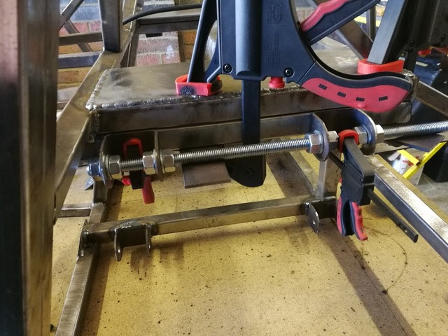
Making up a nose bracket for the diff is on the to-do-list. just waiting for poly bushes to arrive for the diff top mounts.
Bracket will bolt to top and bottom of diff and CP10/SB4
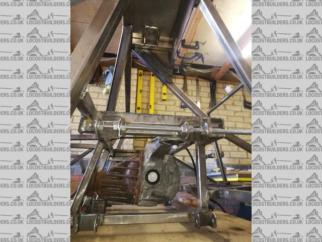
Description
I also had a chance to clean up and separate the donor parts. The brakes are definitely much newer than the rest of the car.
The rubber seals on them are actually OK. but one bleed nipple did snap off, I managed to weld on a nut and get it out.
Tomorrow's job is adding the front wishbone brackets.
I still need to make up the wishbones, I cut all of the wishbone plates from 5mm plate already.
I have all of the parts I need to get it rolling now, just as well because I lose the garage on the 5th May!
Does anyone want the build table?
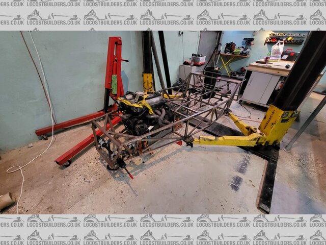
Half Finished - 20/2/21 at 07:39 PM
So I moved and lost my garage since the last update. Everything has been sitting in a damp lockup since..
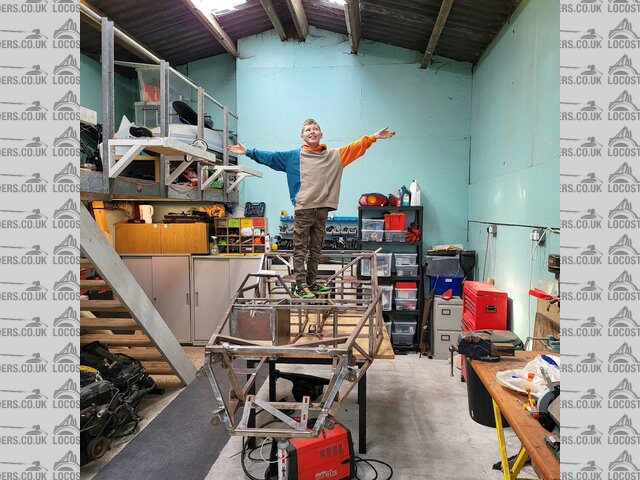
Recently got myself a new space with a 2 post lifter.

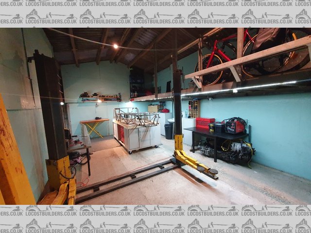
Description
More to follow.
ianhurley20 - 20/2/21 at 09:36 PM
Now I'm jealous
Half Finished - 1/5/23 at 08:08 AM
I recently picked this back up after being occupied with other projects. I had a check list of items to finish before paint that took ages.
I can see why so many of these projects ended up on eBay as unfinished projects..
Column supports

Description
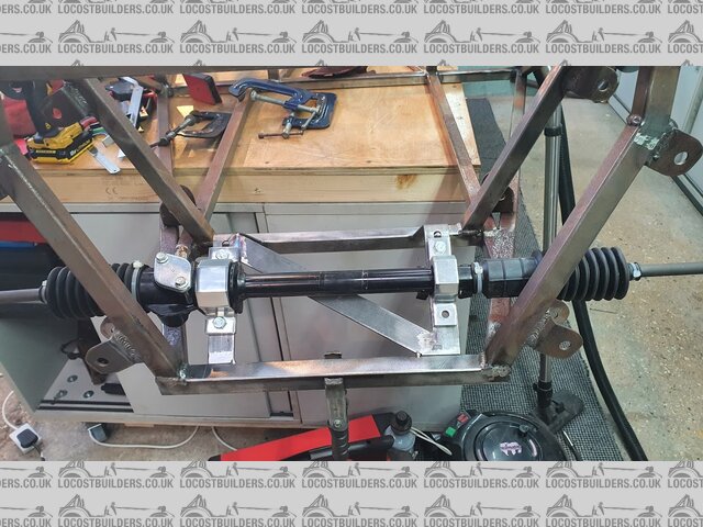
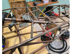
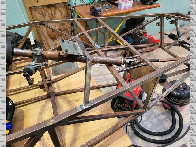
Getting the engine aligned, I adjusted the bottom of the bellhousing to be level with the bottom chassis rails

Description
Gearbox support was tricky, there isn't any space above the gearbox. so the rubber bush slots in from the front.

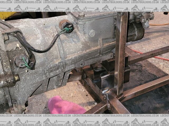
Description
Engine mounts made up

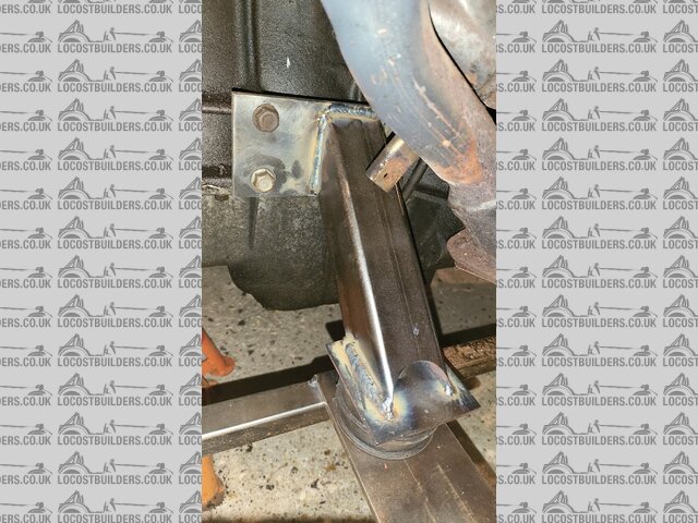
Description
Seat supports and handbrake supports. The handbrake is a Sierra part offset to the side. I made up an adjustable link to go with the MX5 handbrake
cables.

Description
Polo rad supports

Description

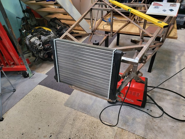
Description
MX5 Column supports, with a small amount of adjustability.
Description
For the side supports I don't have a roll bender, this worked to form the steel bar around the side support plate.

Description
Side supports finished

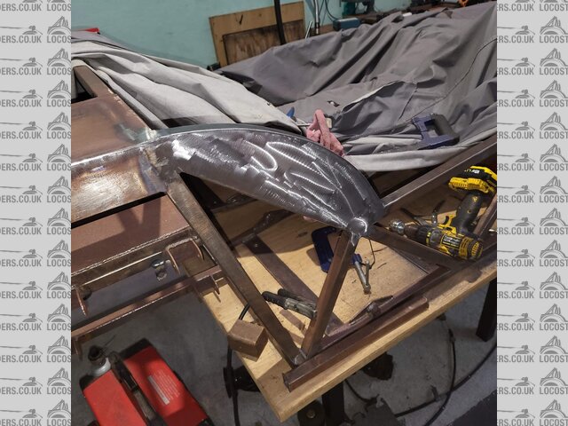
Description
With the chassis finally finished I started prepping it for paint.

Description
Tools you wish you bought sooner...

Description
Before

Description
After.
I'm using POR15. This is after using the cleaner degreaser and then their metal etch.

Description
And after first coat of paint

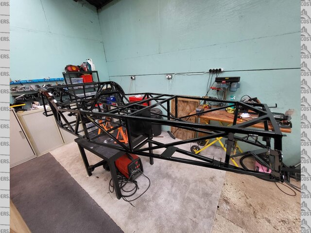
Description

Description
And second coat

Description
Next time, I'll just buy one.
Slimy38 - 1/5/23 at 08:16 AM
Good progress, well done! Did you check the steering column for the sufficient angle deflection? Mine is pretty much the same as yours and it ended up
perfectly in line, I had to move the middle bracket outwards to get more of an angle. It also has the added benefit of clearing the engine a little
more.
JoelP - 1/5/23 at 08:34 AM
Thanks for sharing, I enjoyed reading that.
Half Finished - 1/5/23 at 08:34 AM
I have some adjustment in the column left to right in the bottom mount.
If it's inline with the driver it's under 10 degrees, But it can be offset to meet the 10 degrees.
James - 3/5/23 at 11:45 AM
Great project.
Following with interest and great nostalgia!
Slimy38 - 3/5/23 at 03:02 PM
quote:
Originally posted by Half Finished
I have some adjustment in the column left to right in the bottom mount.
If it's inline with the driver it's under 10 degrees, But it can be offset to meet the 10 degrees.
Aye, that's pretty much what I found when I set everything up the first time, I didn't have adjustment in mine though. I had to be a bit
more enthusiastic with the grinder and welder to get things in the right place!
Half Finished - 3/5/23 at 03:35 PM
My next issue is the rear wishbones. The saturn plans have missing dimensions and I've been trawling through old posts to try and find a
definitive answer. It seems others have ended up with excessive rear camber or adjusters wound too far out.
I really don't want to weld up a set only to find they are wrong. I'm going to reproduce the whole thing in CAD. I could even 3d print a set
of wishbones to check the fit.
christim - 5/5/23 at 10:56 AM
Great to see a build progressing! I'm not sure how many are even buying 1/2 built projects any more, seems fewer and fewer out there nowadays
Slimy38 - 5/5/23 at 01:36 PM
quote:
Originally posted by Half Finished
My next issue is the rear wishbones. The saturn plans have missing dimensions and I've been trawling through old posts to try and find a
definitive answer. It seems others have ended up with excessive rear camber or adjusters wound too far out.
I really don't want to weld up a set only to find they are wrong. I'm going to reproduce the whole thing in CAD. I could even 3d print a set
of wishbones to check the fit.
I hit the same and had to 'make it up'. Because I was starting with the MX5 driveshafts and diff I started with them, ensuring that at rest
the driveshafts were 'comfortable' (IE the joints weren't stretched but also wouldn't bind through the full suspension travel).
That gave me the upper and lower positions of the MX5 uprights. With the chassis mountings already defined it was just a case of 'connecting the
holes'.
I did include a level of adjustment in the upper wishbone, I think it goes from about 0 to -10?
Half Finished - 5/5/23 at 07:01 PM
Cheers Slimy38. I'm looking through old posts on here and the Haynes forum, I really can't make much sense of the measurements.
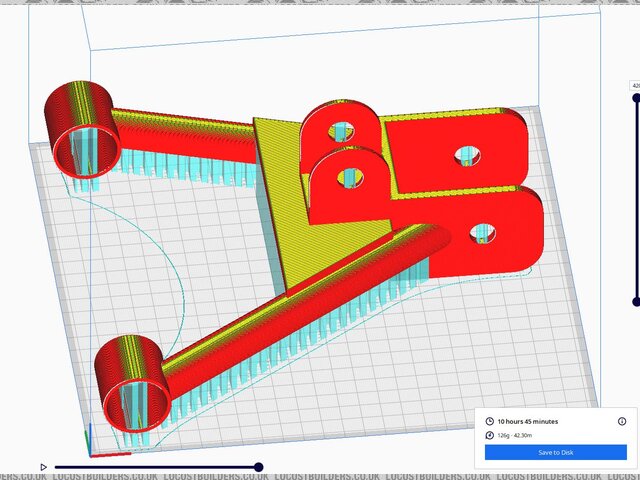
I've just made up the rear upper wishbone based on this Haynes forum post. I'm
3D printing it now so I can check the fit before I commit to welding anything.

Description
Half Finished - 5/5/23 at 07:37 PM
I've also just found this amazing 3d model of the hubs. This will make things easier.
MX5 Hubs
Slimy38 - 6/5/23 at 07:44 AM
quote:
Originally posted by Half Finished
Cheers Slimy38. I'm looking through old posts on here and the Haynes forum, I really can't make much sense of the measurements.
I've just made up the rear upper wishbone based on this Haynes forum post. I'm
3D printing it now so I can check the fit before I commit to welding anything.
Description
Nearly 11 hours for the print? Wow, that's dedication! Mind you, my 3D printer would be taking days to do the same, and that's even if the
print bed was big enough.
I just used lengths of steel and clamps to put everything in place, I'm sure wood sheets and plastic tubes got involved somewhere along the way
too.
Half Finished - 6/5/23 at 11:20 AM
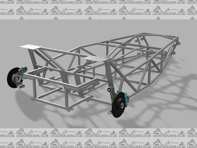
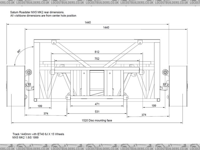
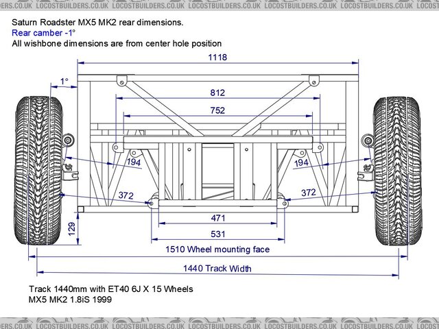
So after manipulating some free CAD models. I've made this.
It's wider than the previous drawings but then then the MK2 MX5 has a 10mm wider track, which adds to the confusion a bit.
I'm starting to make up my wishbones based on this.

Description

Description
Edited to add a version corrected for ride height and -0.5 degrees camber:

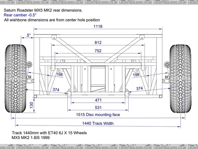
Description
This link lets you open the model in a web browser and take your own measurements:
CAD File
sources:
https://grabcad.com/library/haynes-roadster-chassis
https://grabcad.com/library/mx-5-wheel-and-tire-1
https://grabcad.com/library/miata-nb-non-sport-disc-brake-assembly-1
[Edited on 6/5/23 by Half Finished]
[Edited on 6/5/23 by Half Finished]
Half Finished - 5/6/23 at 08:20 PM
I've been making some progress on this. It's almost a rolling chassis.
Floor cut out. I've left some additional material on the inside edges for some rivnuts. I'll add a removable cover here.
Description
Cleaned up the hubs. Ready for paint

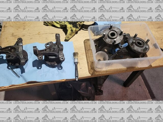
Description
Offering up the rear wishbone to check the spacing. It looks good.
In the end I adjusted my last drawing slightly to -1 degree camber, with the adjusters on the lower wishbone I've got some adjustment for the
camber.

Description

Description
All 8 wishbones done.

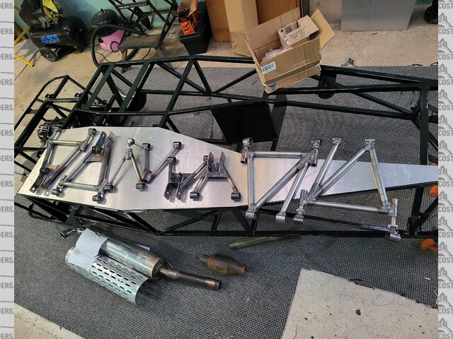
Description
Next job is painting and assembly. I've got the wrong universal joint for the steering rack. My part is for a sierra but I need a group 4 /
Escort short type. Does anyone have one or want to swap? A new one seems to be Ł60.
[Edited on 6/5/2023 by Half Finished]
[Edited on 6/5/2023 by Half Finished]
Half Finished - 12/6/23 at 08:57 AM
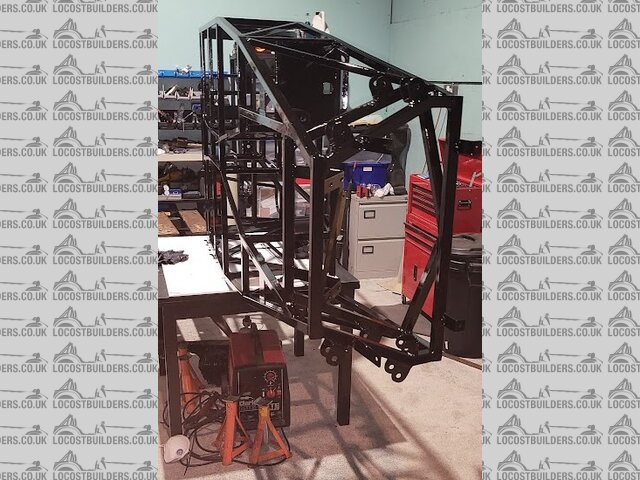
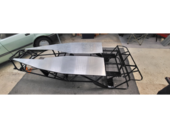
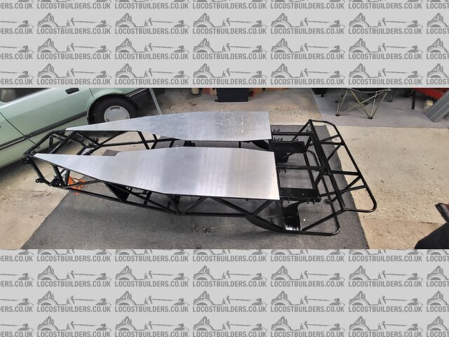
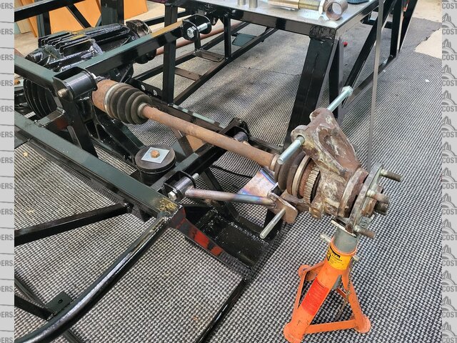
After a long few days in the garage, it's now a rolling chassis!

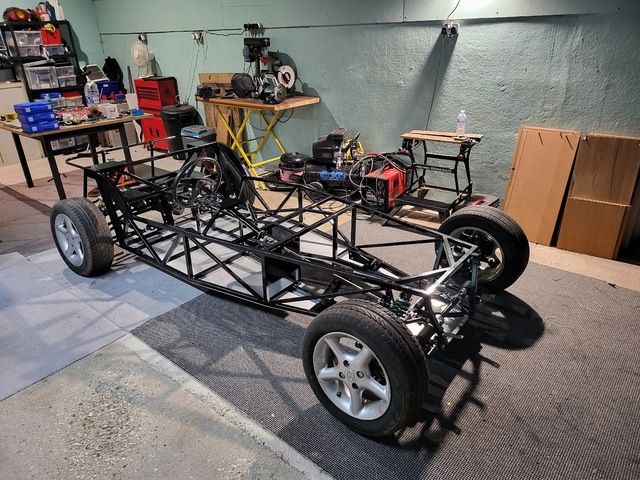
Description
Prof_Cook - 12/6/23 at 07:13 PM
Looks really good!
Mr Whippy - 13/6/23 at 06:27 AM
superb progress and a fantastic workshop
Half Finished - 13/6/23 at 10:24 AM
Thank you for the feedback.
Has anyone requested a VIN number from the DVLA recently? What's your experience been like?
Half Finished - 23/6/23 at 08:06 AM
I'm in the middle of paining the brake calipers right now. I'm also running the brake lines.
Unless I've missed it the IVA manual doesn't specify a fixing distance, is there a best practice for this?
Also, can I put the brake switch on a 4 way union in the rear? Most builds seem to include this in the front close to the master cylinder.
And lastly, do I need the MX5 bias valve? I'm not sure on the layout for this.
Slimy38 - 23/6/23 at 08:44 AM
quote:
Originally posted by Half Finished
I'm in the middle of paining the brake calipers right now. I'm also running the brake lines.
Unless I've missed it the IVA manual doesn't specify a fixing distance, is there a best practice for this?
Also, can I put the brake switch on a 4 way union in the rear? Most builds seem to include this in the front close to the master cylinder.
And lastly, do I need the MX5 bias valve? I'm not sure on the layout for this.
I did my clips roughly six inches apart down the transmission tunnel, the other distances were more constrained by where the bends were going to be.
The plan I used was that if they can move, they can fail. So at it went round the corner I would add an extra bracket.
I personally went for a pedal related brake switch as per the donor car. I'd heard some horror stories about trying to get a pressure based brake
switch working, and I thought having the brake switch left at the pedal was going to be easier to set up.
The bias valve is an interesting one, here's my original question with a few answers;
https://www.locostbuilders.co.uk/viewthread.php?tid=211283
In the end I kept it;

Half Finished - 23/6/23 at 09:40 AM
quote:
Originally posted by Slimy38
I did my clips roughly six inches apart down the transmission tunnel, the other distances were more constrained by where the bends were going to be.
The plan I used was that if they can move, they can fail. So at it went round the corner I would add an extra bracket.
I personally went for a pedal related brake switch as per the donor car. I'd heard some horror stories about trying to get a pressure based brake
switch working, and I thought having the brake switch left at the pedal was going to be easier to set up.
The bias valve is an interesting one, here's my original question with a few answers;
https://www.locostbuilders.co.uk/viewthread.php?tid=211283
In the end I kept it;
Thank you, I did spot your thread. But that link for the diagram is dead. Where do the lines run to on your picture please? Two out from the bias
valve and one more from the master cylinder?
I did save the brake switch from the donor, I'll just use that then. Pedal box is on the to do list as well.
Slimy38 - 23/6/23 at 09:54 AM
Does this help;

It was the loop back through the master cylinder that I could never figure out. If you just look at the valve first, you have one input (A), that goes
to three outputs, front left, front right and rear. I don't know why the front left loops back through but I replicated it.
[Edited on 23-6-23 by Slimy38]
Slimy38 - 23/6/23 at 09:59 AM
This post has an interesting solution to the brake switch;
https://www.locostbuilders.co.uk/viewthread.php?tid=200618
Half Finished - 23/6/23 at 11:03 AM
Thank you for the info, I'll see how far I get with it this weekend. I need to get the brakes working so I can get it down the ramp leading to
the workshop.
I'm starting an expat job later this year. I've not worked out what to do with the chassis yet...
Half Finished - 22/9/23 at 02:05 PM
Just a quick update, I moved to Hungary since my last post and life has been manic!
I cleaned up the brakes and painted them with POR15 caliper paint. They look pretty good finished.
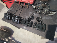

Description
My priority was getting the handbrake working, so that I could move the chassis without it crashing down a steep ramp from the garage.
This is a mix of Sierra and MX5 parts. I've got an issue with the cables fowling the chassis as they exit from the caliper, I still need to
modify this.

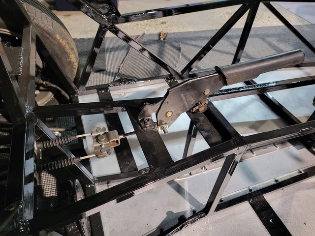
Description
I hired a box trailer and drove a 3000(!) mile round trip.

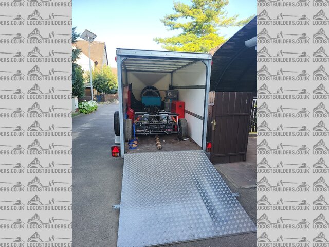
Description
And the new garage even has a pit!

Description
I'm now looking at the parts needed to complete, I had a few questions if anyone knows and could help please?
-Fuel system, Am I best sticking with the MX5 sender or using an out of tank pump? I see that both variants of fuel tank are available.
-Brake lines, has anyone used the made to order parts from Hel Performance? The builder is slick and they are just Ł29.99 per line? available in
Europe too
https://auto.helperformance.com/custom-car-braided-brake-lines
-Shocks and springs, based on other threads I'm going to get GAZ shocks, 14" open, 9.5" closed. with 8" x 250 lbs. & 8" x
350 lbs. springs.
-Are GAZ gold shocks worth the extra? and is there any appreciable difference between 1.9" or 2.25" springs?
-Bodywork, I'm going to get the full set from Equinox. But I've added the steel supports already at the back. Will I be able to fit the rear
panel or will I be cutting stuff away?
[Edited on 9/22/2023 by Half Finished]


