RazMan
|
| posted on 11/1/06 at 09:01 PM |

|
|
Wiring of Savage Switches & Lights for night & day driving
I'll be looking at wiring the dash soon and how the Savage range of switches can be configured.
The switches have led lights behind the legend and it would be useful if this light could be used for both backlighting and warning purposes - i.e.
1. Day - Full on when activated
2. Night - Dim backlighting and full on for activated state.
Has anyone played around with this type of setup? I would imagine a common series resistor would do the trick, with maybe a link to the car's
lighting circuit to toggle the brightness level at night.
I can't find a supplier of the lights which match the switches (main beam, oil, indicators etc) Anyone found one?

Cheers,
Raz
When thinking outside the box doesn't work any more, it's time to build a new box
|
|
|
|
|
RichieC
|
| posted on 11/1/06 at 09:24 PM |
|
|
Im planning on using them too and would also like the idea. Like the fan overide, dim at night, bright when fan is on.
Sorry I cant offer any help though
Rich
|
|
|
k33ts
|
| posted on 11/1/06 at 10:31 PM |
|
|
ive got those switches look cool lit up got them off of zxrlocost on this site
you could use a double switching relay to dim the lights when the side lights are switched on , switching it through to a resistor very simple
todo.
i could draw u up a diagram if u want.
|
|
|
RichieC
|
| posted on 11/1/06 at 10:34 PM |
|
|
That would be great mate
Rich
|
|
|
stevebubs
|
| posted on 11/1/06 at 10:39 PM |
|
|
Ditto - can't be bothered to play about with resistors...but if some soul happens to post a valid one, a few may just find their way into my car
|
|
|
k33ts
|
| posted on 11/1/06 at 11:01 PM |
|
|
not sure about resistor size yet will have to try a few for brightness t night
|
|
|
k33ts
|
| posted on 11/1/06 at 11:05 PM |
|
|
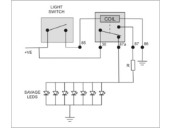
you would obviously use this one relay for all switches so if you wanted them to come brighter when switched on (will only work at night or when
lights on) you could connect the output from the switch to the led and there would need tobe a diode on each switch from the relay supply if that
dont make sense ill do another pic
for how razman wants it its simply resistor inline of side light supply
the switched live to the led with adiode between the side light supply
[Edited on 12/1/06 by k33ts]
|
|
|
k33ts
|
| posted on 11/1/06 at 11:07 PM |
|
|
this would auto dim at night be on full in day
[Edited on 12/1/06 by k33ts]jpeg.JPG)
|
|
|
stevebubs
|
| posted on 12/1/06 at 09:50 AM |
|
|
Circuit is simple enough; Any suggestions on resistor size?
[Edited on 12/1/06 by stevebubs]
|
|
|
RazMan
|
| posted on 12/1/06 at 10:39 AM |
|
|
If I remember my college circuit theory (which was 30 years ago  ) the resistor value would depend on the number of LEDs in parallel. Ideally every
LED should have its own resistor but that would complicate things and k33ts's circuit is a good compromise ) the resistor value would depend on the number of LEDs in parallel. Ideally every
LED should have its own resistor but that would complicate things and k33ts's circuit is a good compromise
 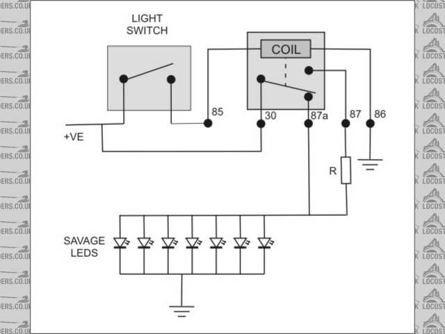
Rescued attachment Savage Circuit Diagrams.jpg
Cheers,
Raz
When thinking outside the box doesn't work any more, it's time to build a new box
|
|
|
rusty
|
| posted on 12/1/06 at 11:33 AM |
|
|
I dont see the need for a realy as long as you put some diodes in to stop the light trying to run the device being switched and visa versa. WOuld post
a diagram but not sure how to post pics.
|
|
|
DarrenW
|
| posted on 12/1/06 at 11:54 AM |
|
|
Sounds a bit overly complicated to me. Nearly all of mine light up when i put lights on. Only exception is hazard switch that flashes when hazards are
on. All other tell tales are on the DD2. Ive been driving in winter daylight with sidelights on as a better warning to other drivers so switches are
on most of time. I dont find them to be overly bright during night. If you think they are why not use one of those dimming wheels (rheostat?) that
most cars have nowadays so you can turn them down?
(If you use DD2 you need to be mindful that the indicator tell tale soent work with ignition off - fail point for hazard operation).
|
|
|
rusty
|
| posted on 12/1/06 at 11:56 AM |
|
|
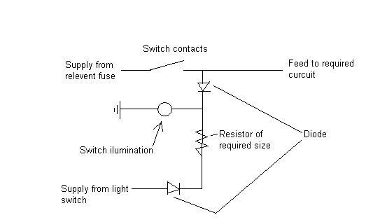
This curcuit will do the following.
During normall day driving, ie lights turned off, the switches will not be iluminated enless the switch is activated.
During night driving, ie light on, the switch will be ilimunated to a level dependent on the resistor and will go to full brightness when the switch
is turned on.
|
|
|
RazMan
|
| posted on 12/1/06 at 12:14 PM |
|
|
Rusty, I wasn't sure how to use diodes but your diagram makes it clear to me now. I suppose either method will have the same effect but yours
will need one diode for every switch whereas my relay method only requires 2 components for any number of switches.
Is there a particular type of diode for this application?
Cheers,
Raz
When thinking outside the box doesn't work any more, it's time to build a new box
|
|
|
RazMan
|
| posted on 12/1/06 at 12:22 PM |
|
|
quote:
Originally posted by DarrenW
Ive been driving in winter daylight with sidelights on as a better warning to other drivers so switches are on most of time. I dont find them to be
overly bright during night.
My intention was to make the state of the switches obvious during daylight (full brightness when on) and tone them down for night driving while adding
a subtle backlighting to all switches in the 'off' state so you can easily find them in the dark *plus* the full on indication.
[Edited on 12-1-06 by RazMan]
Cheers,
Raz
When thinking outside the box doesn't work any more, it's time to build a new box
|
|
|
rusty
|
| posted on 12/1/06 at 01:17 PM |
|
|
The type of diode depends on the current load but as the switches use LED's it is not alot.
1N4001 1A Rectifier diode 50V max are 4p from my supplier but in maplin 1N4006 1A 800V 7p each maplin code QL78K
|
|
|
MikeRJ
|
| posted on 12/1/06 at 01:43 PM |
|
|
Paralleling LED's like that doesn't usualy work very well, as the voltage drops are never identical, so the one with the lowest Vf hogs
most of the current, making it brighter. It's always best to have 1 resistor per LED.
You will also need a hand full of diodes to prevent reverse feeding the other LED's when one LED is set to full brightness.
Couple of circuits here. The first one requires 2 diodes and 2 resistors per LED. Taking the first LED as an example, the night illumination current
is determined by R1+R2, and the "active" current is set by R2.
The "deluxe" version uses a voltage regulator to set the night illumination current. This means you can control the night illumination
brightness of all the LED's with a single potentiometer. It uses 1 diode and two resistors per LED.
Please note the LED resistor values are guesses, they will probably need to be adjusted by experimentation to see what brightness level you prefer.
[Edited on 23/6/07 by MikeRJ]
|
|
|
RazMan
|
| posted on 12/1/06 at 02:15 PM |
|
|
This must be what its like to be part of the Borg collective !! Thanks for all the ideas guys
Mike, your diagrams are exactly what I had in mind - controlling the levels with a pot is ideal. One thing that springs to mind is the fact that the
led's in the switches must already have a resistor in series to operate on 12V. This resistor may have a bearing on the value of the external
components used (although I haven't a clue how) I have dismantled a switch and the led looks like a tiny filament bulb with a metal case and a
contact on the bottom. The resistor is possibly inside this case.
As the switches' spade terminals are quite tiny it will be difficult to terminate multiple wires onto them. IMHO the best way to connect
everything would be to make a small pcb which will contain all components. Flying leads would then go to the switches and 'choc blocks'
used for the loom connections. Does that sound feasable?
[Edited on 12-1-06 by RazMan]
Cheers,
Raz
When thinking outside the box doesn't work any more, it's time to build a new box
|
|
|
rusty
|
| posted on 12/1/06 at 03:21 PM |
|
|
I based my curcuit on the switch ilumination being 12v ready hence only one resistor.
I also agree that have one resistor per LED is a much better option and making up a PCB or strip board with all components would make a neat job.
[Edited on 12/1/06 by rusty]
|
|
|
MikeRJ
|
| posted on 12/1/06 at 05:54 PM |
|
|
quote:
Originally posted by RazMan
As the switches' spade terminals are quite tiny it will be difficult to terminate multiple wires onto them. IMHO the best way to connect
everything would be to make a small pcb which will contain all components. Flying leads would then go to the switches and 'choc blocks'
used for the loom connections. Does that sound feasable?
[Edited on 12-1-06 by RazMan]
That's exactly how I would do this, put all the electronics in one place rather than have components hanging off the backs of switches etc.
|
|
|
RichieC
|
| posted on 13/1/06 at 07:04 PM |
|
|
Some great replies. Its years since I did electronics at school so Im going to have to have a good think, but heres another one for the pot.
The savage rear fog switch is non latching so its going to need a relay I guess to latch it on, so push on, push off. Is this easily incorporated
into the above illumination ?
Thanks for any advice, only got a rough idea of how to do this
Rgds
Rich
|
|
|
RazMan
|
| posted on 13/1/06 at 07:54 PM |
|
|
Rich, It would appear that Savage, in their infinite wisdom, made a few of their range momentary (not latching) and they have been subject to a number
of returns regarding this obvious error. The fan switch suffers from the same fault apparently. It is probably worth having a word with your supplier
to see if anything can done - the switches / button assemblies / legends are all interchangeable so as a worst case you could buy another latching
switch and swop the parts over - but not the cheapest solution.
Cheers,
Raz
When thinking outside the box doesn't work any more, it's time to build a new box
|
|
|
RichieC
|
| posted on 13/1/06 at 08:20 PM |
|
|
Ah sorry, it is the fan Im thinking of as I bought a fan and a rear fog from zxrlocost on here. I queried it at the time and the response was, that
was the way savage intended and any latching had to be done with a relay.
Bit dissapointing considering the price
Thanks
Rich
|
|
|
RazMan
|
| posted on 13/1/06 at 09:14 PM |
|
|
I think that is what's called a cop out Rich. How can they justify a non latching fan switch but have a latching aircon switch and who wants to
design in a switch which needs a circuit board to do a simple job anyway? 
I was told by the supplier that I bought mine from (but only a couple for evaluation purposes) that the fan switch issue has been resolved. I am
presently looking for about 10 switches & lights (including a fan) so it will be interesting to see which version I get
Cheers,
Raz
When thinking outside the box doesn't work any more, it's time to build a new box
|
|
|
RichieC
|
| posted on 14/1/06 at 07:38 AM |
|
|
Aye, certainly sounds like it. Ive mentioned it again to zxrlocost and hes going to exchange it with Savage.
Does anyone fancy making up some PCBs for this? I like the idea of using the pot to adjust the "dim" night mode, would it also adjust the
"full bright" when activated? Ive never used the predrilled type PCBs before, only UV etching and that was years ago.
Thanks
Richie
|
|
|