I'm hoping I've missed something blindingly simple and hope to be enlightened

[Edited on 21/11/11 by Mr C]
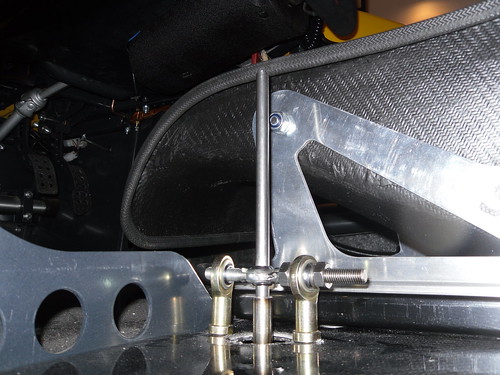
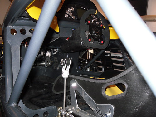
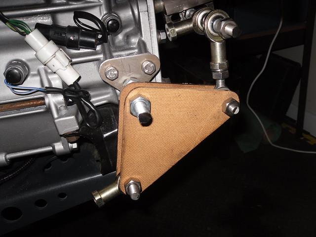
I'm attempting to design and make my own gearchange mechanism. Its for a subaru gearbox converted into a mid engined configuration. I've
currently got as far as the set up shown in the images, albeit the homemade parts have been replaced with machined components. The current problem is
the pattern is "upside down" 2nd is where 1st should be and 3rd is where 4th should be. Although I can live with this, I am worried that a
wrongly selected gear, resulting in engine damage may occur. So I'm looking for suggestions, thoughts etc, to get the pattern right. Cable change
mechanisms do not seem to work well with this box so is not an option. I would prefer to use existing mounting holes etc and the mechanism has to be
simple and robust.
I'm hoping I've missed something blindingly simple and hope to be enlightened
[Edited on 21/11/11 by Mr C]
I have a very similar problem in that I had considered modifying my gear change unit like you have. I think however I am going to risk it though and and turn the volvo gear change unit around and have new control cables made. this will mean my gears will be upside down for a volvo 850. My box was cable operated all along however.
Could you consider using the mechanism from a mid/rear engined car?
On my GTM Libra I used an Elise mechanism when I got rid of the rod change. It does use cable though.
911 could be an option too.
Failing that have you looked at the Ultima rod change?
Hello matey
i have been following this on your blog, i may have a solution to your problem u2u me your email and ill send u a diagram of what you will have to do
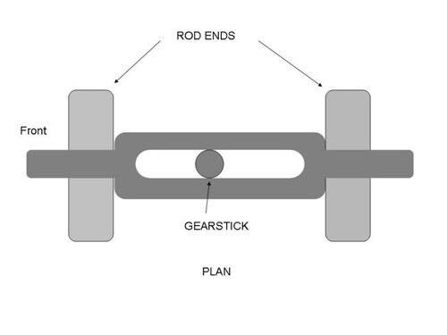
Surely it is simply a matter of changing the relatinship of the pivot & operating rod? At present you have pivot at centre & operating rod
below, if you move the operating rod to above the pivot everything will work "backwards" therefore making it the right way round for your
installation.
Seems, very straightforward unless I am missing something entirely?
Where might i find a link to your blog.
quote:
Originally posted by jack_t
Hello matey
i have been following this on your blog, i may have a solution to your problem u2u me your email and ill send u a diagram of what you will have to do
quote:
Originally posted by liam.mccaffrey
Where might i find a link to your blog.
quote:
Originally posted by jack_t
Hello matey
i have been following this on your blog, i may have a solution to your problem u2u me your email and ill send u a diagram of what you will have to do
As above - surely it's just a case of shifting a pivot point either at the front or back of the car?
Thanks all for such a rapid and helpful response, amazing.
My blog is Scoobystorm
The design is based on what I've seen on Ultimas and also a GD setup. The gearbox is originally rod and doesn't like cable particulary
because of 5th and reverse being internally strongly spring loaded.
As Jack stated, the rod needs to rotate
Thanks again all.
Mike
quote:
Originally posted by russbost
Surely it is simply a matter of changing the relatinship of the pivot & operating rod? At present you have pivot at centre & operating rod below, if you move the operating rod to above the pivot everything will work "backwards" therefore making it the right way round for your installation.
Seems, very straightforward unless I am missing something entirely?
quote:
Originally posted by MikeRJ
quote:
Originally posted by russbost
Surely it is simply a matter of changing the relatinship of the pivot & operating rod? At present you have pivot at centre & operating rod below, if you move the operating rod to above the pivot everything will work "backwards" therefore making it the right way round for your installation.
Seems, very straightforward unless I am missing something entirely?
It depends on the OP's interpretation of "upside down". If 1st is where 2nd should be, and both 1st and second are to the right of 3rd and 4th then this will work. If 1st and 2nd are correctly located to the left of 3rd and 4th, then changing the pivot will fix one problem and introduce another. i.e. does only the push/pull motion need to be reversed, or does both push/pull and rotation of the operating rod need to be reversed?
Jack, U2U sent, thanks, Mike
From the above gear pattern a simple swap of the operating rod/pivot position will do the job.
quote:
Originally posted by russbost
From the above gear pattern a simple swap of the operating rod/pivot position will do the job.
quote:
Originally posted by MikeRJ
quote:
Originally posted by russbost
From the above gear pattern a simple swap of the operating rod/pivot position will do the job.
I still don't understand how moving the pivot will reverse only the push/pull and not the rotation? Could you do a quick sketch?
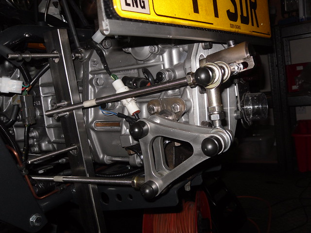
At the moment, standing at the rear end of the car and looking forwards, moving the gear lever left will turn the operating rod clockwise i.e. the rod turns in the opposite direction to the gearlever pivot. Pushing the gearlever forward will move the operating rod backwards. The rotation must be preserved whilst the push/pull motion reversed.
I can't see a simple solution to this without adding additional linkages.
Now in fairness I did say "Seems, very straightforward unless I am missing something entirely?" which I was!
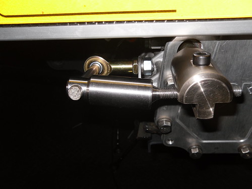
Sorry, should have looked more closely at the pics, I was asssuming it was a twin rod system & you'd only pictured part of it, I didn't
look at the third pic where it's more obvious!
I would therefore have to agree that without splitting the 2 motions I can't see an easy way of doing it.
Is this in an SDR storm? Actually doesn't matter whether it is or not as they use that engine & box IIRC, how do they get around the problem,
presumably they aren't selling kits where you finish up with a backwards gearshift, so they must have found a way around it???
If you make the pivot point for your gearstick the bottom set of balljoints and have the actuation rod coming from the top set of balljoints when you
push the stick forwards the actuation rod will go forwards instead of backwards.
Or am I missing something too?
Cheers!
quote:
Originally posted by russbost
Now in fairness I did say "Seems, very straightforward unless I am missing something entirely?" which I was!
Sorry, should have looked more closely at the pics, I was asssuming it was a twin rod system & you'd only pictured part of it, I didn't look at the third pic where it's more obvious!
I would therefore have to agree that without splitting the 2 motions I can't see an easy way of doing it.
Is this in an SDR storm? Actually doesn't matter whether it is or not as they use that engine & box IIRC, how do they get around the problem, presumably they aren't selling kits where you finish up with a backwards gearshift, so they must have found a way around it???
quote:
Originally posted by v8kid
If you make the pivot point for your gearstick the bottom set of balljoints and have the actuation rod coming from the top set of balljoints when you push the stick forwards the actuation rod will go forwards instead of backwards.
Or am I missing something too?
Cheers!
this any help to you??
http://www.youtube.com/watch?v=RJZiZfE_IoE&feature=related
Mike
2 suggestions, first would it be possible to split the gearchange into 2 x rods, with one doing the rotation & the other doing the fore/aft
motion. Can't be 100% certain looking at your setup from the pics but it looks as tho' you may be able to keep the lower rod to control the
rotating motion (which is in the correct plane as it is) tho' you would have to incorporate some sort of "slide" at the rear end to
stop from controlling the longitudinal motion & add an upper rod which would do the fore aft?
The other thing I would say is that there is no reason at all why a cable shift should be "wooly" or vague, the original MR2 which is what I
use as a donor for the Furore had a fairly precise shift & even controlling it from a position around 3 feet further forward with longer cables we
still get a precise shift. I would emphasise tho' that for the car shift we pay about �150 for bespoke cables, which, like the originals are
quite beefy. When using a bike engine we just use a teleflex cable, & I've heard of people using teleflex (or morse) cables for car shifts,
but personally I never would. However there are plenty of car cables around, which I would think would be long enough for your application without
needing modification, might be worth thinking about??
Russ thanks for your response, very helpful, potentially I would go to two rods if I can't get one to work and its better than the cable option
in terms of complexity and use. I'll keep this open as an option. One of the challenges is the routing of rods front to back, there are not
many/any options. The other challenge is the 5th/reverse gear which is heavily sprung. This is presenting a challenge for the cable setup according to
Jason at scoobybits(posted on exocars) and adjustment is tricky to say the least.
As well as work well the mechanism is on show at the back of the car so I would like it to look good as well (maybe too many asks on my part
I don't know why the cable system is not working as well as you say it should, perhaps Simon Dickens might be able to shed some more light on
this. If it did work well and was available I would gladly take it in preference to my own lashup 
I've come up with the arrangement below hope it makes sense. The UJ at the bottom of the gearstick would have to be modified to give left/right
movement only.
How well would this work given there is no fixed pivot point fore and aft?
jack_t is also thinking about options at the gear box end, thanks Jack, so I'm hopeful we can crack this.
Russ and all, just done a quick drawing of proposed UJ setup on the end of the gearstick in line with my previous thoughts and suggestions
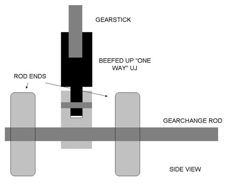
The back is to the left of the image, hope it makes sense.
Mike
Any help with this of mine....?
It's a hybrid rod/cable system
[img]

gc1
[/img]
Trying to make quite sure I understand what you have at the moment, between the 2 rod ends in the pic is the lever sitting in a spherical bearing
allowing the lever to pivot both fore/aft & side to side?
If I'm understanding your drawing correctly & I have understood what you had originally then it's possible, if you modify the lower
joint as you suggest, that it could work, but depending on the length above the lower slide thro' the rod ends I think it quite possible it might
"snag" & therefore make the fore/aft shift stick & jam, if you added further support, perhaps another pair of rod ends in front
& behind the 2 you already have I guess that might do the trick, it's one of those things that a little trial & error in practice is
probably necessary to find an optimum setup.
Although all the gears should then be in the right place, the change might still feel a bit strange as you'd be sliding the gearstick fore &
aft instead of the usual action of pivotting it. An interesting conundrum this one!
I would suggest ask Simon what cables he is using as if they are a bit lightweight the problem with that shift may be nothing more than that.
Hi,
At the moment it looks like moving the top of the gear lever forwards will move the lower control rod backwards because of the UJ at the skin plane,
if this is the case then it seems that if you changed the universal joint to a hinge orientated side to side to control the rotation of the lower rod,
then used a sliding horizontal rod through the upper eye ends so that the whole assembly moved forwards and backwards as you go through the 1-2 change
that would fix your problem. You might have to increase the stiffness of the assembly in the 1-2 plane to keep the gearchange tight.
Duncan
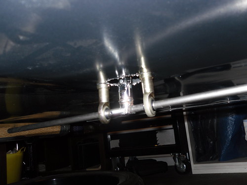
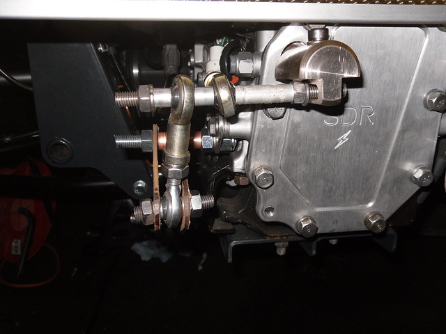
Russ, yes its actually another rod end with a bit of threaded rod welded on below is another view which you can just make it out
I suppose it would be the twisting motion that would cause the snagging, they could be fixed into one position as they don't need to rotate as
such or perhaps get some longer sleeves machined into them.
Alan, that's a nice set up there, I guess the MR2 gear change works using a similar principle? another potential option.
Thanks all.
I'm inclined to agree with Duncan that as long as the assembly is kept stiff then there's no reason why it shouldn't work, certainly adding tubes longer than the rod ends should help.
quote:
Originally posted by dmac
Hi,
At the moment it looks like moving the top of the gear lever forwards will move the lower control rod backwards because of the UJ at the skin plane, if this is the case then it seems that if you changed the universal joint to a hinge orientated side to side to control the rotation of the lower rod, then used a sliding horizontal rod through the upper eye ends so that the whole assembly moved forwards and backwards as you go through the 1-2 change that would fix your problem. You might have to increase the stiffness of the assembly in the 1-2 plane to keep the gearchange tight.
Duncan
Russ, Duncan, Jack et all, a big big thank you, I'll keep you posted.
Mike
Hey Mike,
Looking good! How's the feel on the rod linkage?
This gearchange stuff looks a right PITA. I'm hoping one of you/scoobybits/simon will have got a decent linkage sorted by the time I get round
to it!
Dan
quote:
Originally posted by pezzer
Hey Mike,
Looking good! How's the feel on the rod linkage?
This gearchange stuff looks a right PITA. I'm hoping one of you/scoobybits/simon will have got a decent linkage sorted by the time I get round to it!
Dan
Yeah I know what you mean. I used to drive my brothers Integra type r a lot, and was forever putting the windscreen wipers on whilst going round
roundabouts I guess there's something to be said for conformity!
When I first saw the issues on your blog, I was trying to figure out the options. The best I could come up with was an MR2 shifter with cables and
something on the back a bit like the video fluidslvr posted.
If your's is working well, then I shall be paying close attention to what you do!!!
Dan
Just a quick update, I tried a sliding arrangement though it was not too successful, so I'm reverting back to the reverse pattern arrangement to
get me on the road. At some point I'll look at a rod / cable hybrid system using some of the ideas posted here, so thanks again all for taking
the time to post and helping me on the way.
Mike
Have you seen this:
Link to Subaru shifter on YouTube
Russ
Thanks Russ, yes I think it was posted earlier in the thread by fluidslvr, I believe a gearchange loosely based on this has been developed on
scoobybits democar. Simon is looking to production ise it so I'll hang fire for a little while. The other system that I fancy, though it still
needs an adopter plate developed is this one
linkage
An adopter plate along the same principles of the film clip you posted should work with it. The only down side is cost and as usual with these things
my build budget / costs have spiralled.
Sorry to resurrect this thread, this should have been sorted ages ago but it still festers on. I did opt in the end for the iminent fatory option
gearshift, hoping for delivery in January, but Simon's been deteriorating since I ordered the kit over two years ago and has now caught G-t-itus
along with a serious dose of the darengeorges. So its back to plan A if I want to see this boat anchor on the road for summer. Anyhow enough of the
small talk.
I'm after a kind hearted CAD competent person who can draw some brackets and plates for me so I can get them cut which nicely leads on to the
second bit, I also need someone to cut them. I'm happy to pay a fair and reasonable rate though please let me know before hand as I hate
surprises guestimates, builders quotes and double glazing salesman
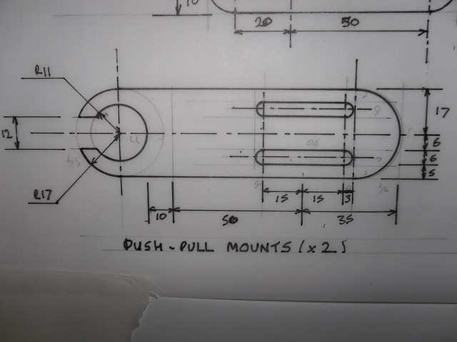
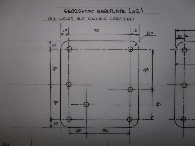
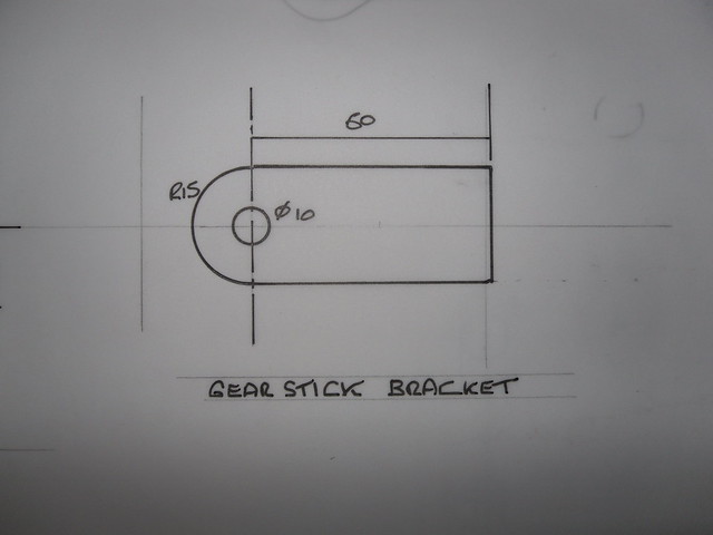
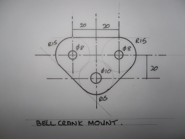
Below is a couple of rough drawings of two of the parts, as a starter for ten I need two of each.
I'll need about another 5 or so pieces done, all a similar level of detail though its dependant on a couple of things this week. any assistance
would seriously be gratefully received as I want this out the way now as its gone on for too long.
Thanks, Mike.
I'll be happy to draw them up in CAD tomorrow or Tuesday evening if no one beats me to it. Can then give you DXF files to give to laser cutters etc..
quote:
Originally posted by eddie99
I'll be happy to draw them up in CAD tomorrow or Tuesday evening if no one beats me to it. Can then give you DXF files to give to laser cutters etc..
I will endeavour to draw the other parts which are all flat plate, and as follows: No Problem, I'll let you know when i get them done Wont owe me anything, it shouldnt take any more than a couple of mins...
[Edited on 18/3/12 by eddie99]
If you want them laser cut, I can put them in with my next batch of laser cutting, they're ok with doing one-offs as long as the overall order is over their min amount (which it will be), just email me the dwg files when Ed's done them. I can obviously get a price on everything b4 committing, tho' they are usually very competitive.
quote:
Originally posted by russbost
If you want them laser cut, I can put them in with my next batch of laser cutting, they're ok with doing one-offs as long as the overall order is over their min amount (which it will be), just email me the dwg files when Ed's done them. I can obviously get a price on everything b4 committing, tho' they are usually very competitive.
Done the brackets, Whats your email and i'll send over the working drawings so you can double check before they go to Russ
What thickness by the way? Just so my CAD models can look neat.
Can you give me the dims for the m6 hole in the gearshift baseplate that is on the left hand side with no height dim.
[Edited on 20/3/12 by eddie99]
The hole to the left is 27.5mm "high" from the bottome edge. Its at the centre point of the two circles to the right. The thickness is 3mm
My email is [removed at request of Mr C]
I'm currently fitting up the new bell crank and a mounting plate for the push pull mounts and cable, once done I'll have the measurements
for the other couple of bits which I should be able to post up tomorrow evening at some point.
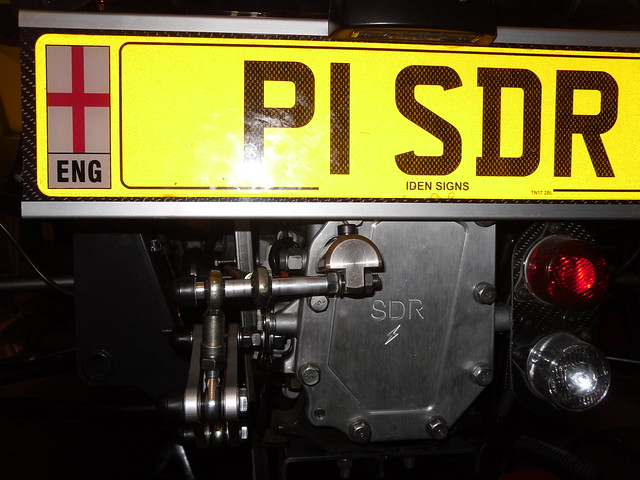
I'll post an image shortly of the rear mechanism, hopefully it doesn't look too Heath Robinson. Anyone viewing, let me know what you
think.
Thanks again Eddie
Mike
[Edited on 4/4/2012 by ChrisW]
I had guessed it was half way, just wanted to check Will email the drawings over tonight.
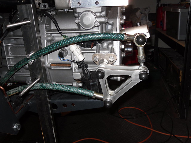
Gearchange as of end of play tonight.
The bit of box section needs to be cut down and mounted properly, the push pull cable brackets will then go on there. the m10 rods currently showing
are temporary and have tape on them which indicates the distance the cables need to be fixed from the rod ends (183mm). The studs coming through the
box section will be cut down. Can anyone spot the rusty bolt that I need to sort?
The view from the back, hopefully not too obtrusive looking.
Gearshift top plate.
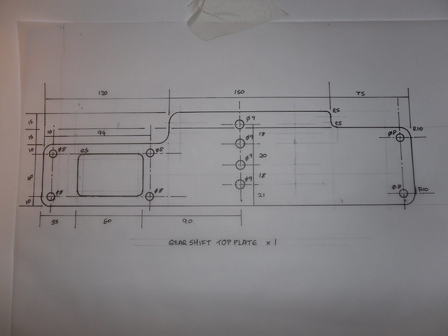
Hopefully the measurements can be seen f not here's a link to the image on flickr
http://www.flickr.com/photos/buckmoreboy/6860539118/sizes/l/in/photos
tream/
One last small bracket to follow
Cheers Eddie.
Mike
Hi mate
Sorry didn't get a chance to email drawings over, now won't get a chance to do the cad till Tuesday, ill try do it all for you Tuesday.
Sorry for the delay
Eddie here's the last two which are quite straight forward
I also need a variation of one of the previous drawings, the "push pull mount" Along the bottom of the drawing is a measurement for 50mm I
also need one that is 80mm.
Hopefully that's it Eddie, with a bit of luck the parts will bolt together, I can get some cables made to measure then hey presto one slick
gearchange and one IVA'd car.
Thank you
Mike
Measured up for the cables and ordered them today. Used "a bit" of garden hose to do the measuring as in the images below. Pleased
there's a hosepipe ban coming as I've not a lot of hose left!!
The gearshift is a toyota GT4 one which I've turned "upside down"
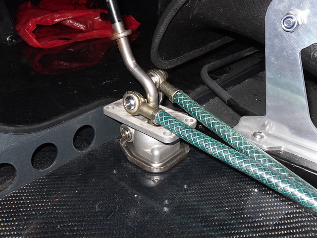
I've gone for 10mm cables designed for use on buses!...a bit overkill though should be up to the job then.
All brackets done, just emailing them to you now in DXF format. Sorry for the delay
Ed thank you again for doing this, the drawings look good.
Russ, I've forwarded the files to you along with quantities I was after them cut in 3mm steel or what ever the closest measurement is to that.
Thank you both for your assistance with this.
Mike
Just a Brief update and big thanks to Russ and Eddie,for helping me immensely with this. I've now got the brackets and plates and been to
screwloose for a few fixings and am spending the rest of the weekend working on this. Hopefully I'll crack it this time, if not there might be
some broken v-storm components going cheap!! I'll keep you informed one way or another.
Front part assembled, will need dismantling and painting at some point once it works hopefully. Russ and Eddie you can see the results of your
invaluable assistance. Hopefully I'll have the back end connected in an hour or so and I'll find out if the blood sweat and tears are worth
it

All done and all working all bar a bit of paint. Thanks to all for inputing ideas, providing support and generally taking an interest Eddie and Russ I
can't thank you both enough.
Link to short video clip linky
(I need to paint that bolt as well!)
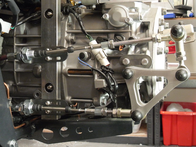
Looks good!
There appears to be quite a lot of flexing in the support connected to the gearbox input shaft. Have you tried it on the road?
quote:
Originally posted by v8kid
There appears to be quite a lot of flexing in the support connected to the gearbox input shaft. Have you tried it on the road?