mattplace
|
| posted on 10/2/05 at 12:44 AM |

|
|
inboard shocks - again i'm sorry!
am going to have inboard shocks on my locost but how do you design a rising rate set-up?
have looked through the archives but can't find any description of designing it.
i am going to use wishboes 'similar' to book ones and have a pusrod going from the lower wishbone (where the standard shock mounts).
i have a collection of r6 shocks (you gotta love e-bay!) and have a standard rocker assembly with one of them so would like to use this in the design
(like grabers on la bala).
i like grabers pull rod system but have decided a pushrod system is the one i want.
any suggestions/ info would be much appreciated.
|
|
|
|
|
NS Dev
|
| posted on 10/2/05 at 12:47 AM |
|
|
Rising rate..........obvious if you think about it......................I'm going to let you work it out, but just think that the effective
spring rate/damper rate is affected by the angle it operates at!
|
|
|
kb58
|
| posted on 10/2/05 at 01:56 AM |
|
|
The angle between the shock and the activating arm should start out less then 90 degrees, and as the shock is compressed, the angle should go *toward*
90 degrees, but not past it.
Apologies will work, to a point. How do you think people figure this stuff out? By reading! You can read the same books we have. Here's my
list:
http://www.kimini.com/Reference/index.html
If you're building a car you better have at least read "Competition Car Suspension" by Staniforth.
This is my one bone to pick with the Locost book. The book "Gives a man a fish and feeds him for a day' while it could have been
"Teach a man to fish and feed him for a lifetime." The book could have at least listed references or given in-depth technical data, and
maybe explained why they picked certain values. Without doing so, people are left to blindly follow along, clueless about to make the smallest
changes. So that leaves people having to read books on their own, not an entirely bad thing.
[Edited on 2/10/05 by kb58]
Mid-engine Locost - http://www.midlana.com
And the book - http://www.lulu.com/shop/kurt-bilinski/midlana/paperback/product-21330662.html
Kimini - a tube-frame, carbon shell, Honda Prelude VTEC mid-engine Mini: http://www.kimini.com
And its book -
http://www.lulu.com/shop/kurt-bilinski/kimini-how-to-design-and-build-a-mid-engine-sports-car-from-scratch/paperback/product-4858803.html
|
|
|
chrisf
|
| posted on 10/2/05 at 02:33 AM |
|
|
Have a read here.
This is what I used to design my pushrod/rocker suspension. In the rear, I used a design similar to Kimini's.
Look at me website for the results. Chech the archived files page. Kimini's right: this does take quite a bit of thought.
--Chris
|
|
|
kb58
|
| posted on 10/2/05 at 04:07 AM |
|
|
Chrisf, what shocks are those?
Mid-engine Locost - http://www.midlana.com
And the book - http://www.lulu.com/shop/kurt-bilinski/midlana/paperback/product-21330662.html
Kimini - a tube-frame, carbon shell, Honda Prelude VTEC mid-engine Mini: http://www.kimini.com
And its book -
http://www.lulu.com/shop/kurt-bilinski/kimini-how-to-design-and-build-a-mid-engine-sports-car-from-scratch/paperback/product-4858803.html
|
|
|
erwe
|
| posted on 10/2/05 at 05:40 AM |
|
|
I made some extra holes for adjustment.
It's not ready jet in the picture, I welded extra support tubes.
[Edited on 10/2/05 by erwe]
Rescued attachment EPSN0132.jpg
|
|
|
kb58
|
| posted on 10/2/05 at 05:56 AM |
|
|
From this angle it looks like your roll center is at ground level. True? Also, how thick a material are the rocker arms. There is a LOT of force
going through rockers, far more then what the car weighs because of the angles.
Mid-engine Locost - http://www.midlana.com
And the book - http://www.lulu.com/shop/kurt-bilinski/midlana/paperback/product-21330662.html
Kimini - a tube-frame, carbon shell, Honda Prelude VTEC mid-engine Mini: http://www.kimini.com
And its book -
http://www.lulu.com/shop/kurt-bilinski/kimini-how-to-design-and-build-a-mid-engine-sports-car-from-scratch/paperback/product-4858803.html
|
|
|
pbura
|
| posted on 10/2/05 at 11:08 AM |
|
|
quote:
Originally posted by chrisf
Have a read here.
Gotta tell ya, I'm pretty proud of that thread! Agreed with NS and kb, though, that if you're going to build a one-off, there's no
substitiute for hitting the books. But differences in interpretation abound, so discussion is good, too.
Erwe's construction looks sturdier than most, IMO, nice job! It looks like the bottom of the tube acting as a fulcrum for the rocker is welded
into position. You could alternatively use a rod end down there to let it float, which might relieve some stress on that joint.
Pete
|
|
|
mattplace
|
| posted on 10/2/05 at 08:20 PM |
|
|
thanks for your replies. i'm sorry for 'rattling a few cages' on this issue. bought the book "chassis engineering" by
herb adams which is very informative but doesn't touch on push rod and bell crank set-ups.
have started making my shock bottom mount today so will get some pics posted soon so you can give your much appreciated opinions.
i know i've posted a few questions this week but was always told, "if you don't know, ask!"
cheers
|
|
|
chrisf
|
| posted on 11/2/05 at 02:09 AM |
|
|
KB:
Sorry for the late reply. Those are the newer R6 dampers. They are really nice and highly adjustable. Let's hope they worl well.
--Chris
|
|
|
kb58
|
| posted on 11/2/05 at 02:34 AM |
|
|
quote:
...i'm sorry for 'rattling a few cages' on this issue..cheers
Just pointing to better sources so someone here doesn't have to type in a long quote from an existing book.
[Edited on 2/11/05 by kb58]
Mid-engine Locost - http://www.midlana.com
And the book - http://www.lulu.com/shop/kurt-bilinski/midlana/paperback/product-21330662.html
Kimini - a tube-frame, carbon shell, Honda Prelude VTEC mid-engine Mini: http://www.kimini.com
And its book -
http://www.lulu.com/shop/kurt-bilinski/kimini-how-to-design-and-build-a-mid-engine-sports-car-from-scratch/paperback/product-4858803.html
|
|
|
turbo time
|
| posted on 11/2/05 at 06:16 AM |
|
|
I used the older R6 shocks, for pricing reasons. I mounted them upside-down, sure it's probably bad, but WTF, that's the beauty of
testing, I can always press bearings in the other end and flip em right side up if they aren't damping properly. I also put in multiple holes
for spring rate adjutment. The only reason I did it the way I did was so that as spring rate softens, ride height increases, which I really wanted. A
concern about the way I did it is the load bearing ability of the upper ball joint. The ones I'm using aren't Ideal, but from what info I
was able to get about them, they are more than good enough (for my application).

[Edited on 11/2/05 by turbo time]
|
|
|
chrisf
|
| posted on 11/2/05 at 02:04 PM |
|
|
quote:
The only reason I did it the way I did was so that as spring rate softens, ride height increases, which I really wanted.
The beauty of CAD is that this does not have to be true. Model it up and you can determine the exact ride height for a given ratio. You then just
adjust the connecting link.
--Chris
|
|
|
Peteff
|
| posted on 11/2/05 at 02:47 PM |
|
|
The new Sylva R10T uses a continuation of the top wishbone as the rocker which is a very neat solution. We looked at bike dampers years ago for a
locost application and found that some use rising rate springs, recognised by their tapering shape but we gave up on them as they were for something
like 400lbs in operation due to the linkage to the swing arm and the damping would not go low enough for the weight of the car.
yours, Pete
I went into the RSPCA office the other day. It was so small you could hardly swing a cat in there.
|
|
|
cymtriks
|
| posted on 12/2/05 at 01:41 PM |
|
|
Position the wishbone pickup as close as possible to the hub. The book wishbone design has a pickup to hub pivot distance of about 4.3 inches giving a
ratio of 0.68. For comparison a Caterham has this distance down to less than 2 inches which from a stress point of view is more than twice as good.
It's also much better from a damper travel point of view and from a spring rate point of view.
The rocker arm, at the top of the push rod, could have a ratio of more than one to increase the spring and damper travel.
For example:-
for a book length wishbone and a distance from the hub to rod pickup of 2 inches the wishbone ratio will be 0.85. Include the effect of a 50 degrees
from vertical pushrod and you get 1.32. Use a rocker with 3.75 inches from the pushrod pickup to the rocker pivot and 5.0 inches to the spring pickup
and you have an overall ratio of 0.99 which is as close to 1 as makes no difference. The spring rate is now the same as the wheel rate and the damper
travel matches the wheel travel.
Spring rates much above 100 cpm are a bit marginal for anything other than flat race tracks. Even the Mc Laren F1 uses 85 cpm at the front and 105 at
the rear. An original Elise uses 90 and 98 respectively though some faster versions are closer to 100 and 110. Lotus and McLaren know what they are
doing!
A word of warning over very hard springs. If the spring is too hard to do its job properly then handling and braking will suffer. Also the true
suspension in the car may well end up being flex in the chassis and damping by the panel rivets wearing away while the springs/damper units do nothing
at all.
|
|
|
britishtrident
|
| posted on 12/2/05 at 03:59 PM |
|
|
For anybody thinking of going this way I say to to thee read carefull the good words wot cymtriks has writ and carve it on tablets of stone. ;-)
More seriously take time to consider the loads this type of set up places on the chassis as they are higher than those from a conventional setup and
carefull consideration is needed on the effect of those loads on the structure, with a sparse spaceframe like the Locost it is too easy to get it
wrong.
|
|
|
Alan B
|
| posted on 12/2/05 at 05:43 PM |
|
|
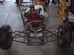
Another variation on the theme.
 
Meerkat front end rolling chassis
|
|
|
kb58
|
| posted on 12/2/05 at 06:03 PM |
|
|
Sorry for using your suspension as an example to the class and I might be wrong, but...
The suspension above appears to be falling-rate and is a good example of what we've been discussing. That's because the angle between the
shock and activating arm looks like 90 at ride height. The problem will be when the shock is compressed; the linkage will move *away* from 90deg. It
needs to move *toward* 90deg to be rising-rate. If how it appears is true, it could be easily fixed by moving the bottom shock mounts outboard far
enough so it's 90deg at full compession.
Or maybe it's fine... hard to tell without several more pictures.
[Edited on 2/12/05 by kb58]
Mid-engine Locost - http://www.midlana.com
And the book - http://www.lulu.com/shop/kurt-bilinski/midlana/paperback/product-21330662.html
Kimini - a tube-frame, carbon shell, Honda Prelude VTEC mid-engine Mini: http://www.kimini.com
And its book -
http://www.lulu.com/shop/kurt-bilinski/kimini-how-to-design-and-build-a-mid-engine-sports-car-from-scratch/paperback/product-4858803.html
|
|
|
Alan B
|
| posted on 12/2/05 at 06:16 PM |
|
|
Kurt, it is actually a little less than 90 degrees, but towards the end of travel it will go past 90 and into falling rate territory.
There is still more to be done, maybe even change of shock to a different length......but hey, I've a body to finish first...
|
|
|
kb58
|
| posted on 12/2/05 at 06:27 PM |
|
|
Agreed... we have to finish first. It's one reason I refrain from bad-mouthing completed cars, because at least they *have* finished, unlike
me...
Mid-engine Locost - http://www.midlana.com
And the book - http://www.lulu.com/shop/kurt-bilinski/midlana/paperback/product-21330662.html
Kimini - a tube-frame, carbon shell, Honda Prelude VTEC mid-engine Mini: http://www.kimini.com
And its book -
http://www.lulu.com/shop/kurt-bilinski/kimini-how-to-design-and-build-a-mid-engine-sports-car-from-scratch/paperback/product-4858803.html
|
|
|
Dale
|
| posted on 13/2/05 at 05:09 PM |
|
|
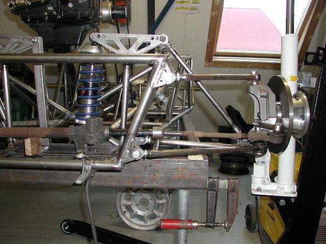
Here is how I did mine and I am pretty sure its rising rate. all pressures are kept on the ball joint plate as well. The whole front is much
narrower than the standard seven and heavier as well. I probably should have left well enough alone but its done and works now.
I have measured the spring rate to be around 130 lbs /inch when using the springs of 180lbs.
Dale
Rescued attachment Resize of DSCF0033.JPG
|
|
|