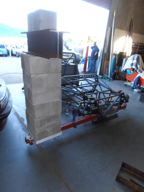
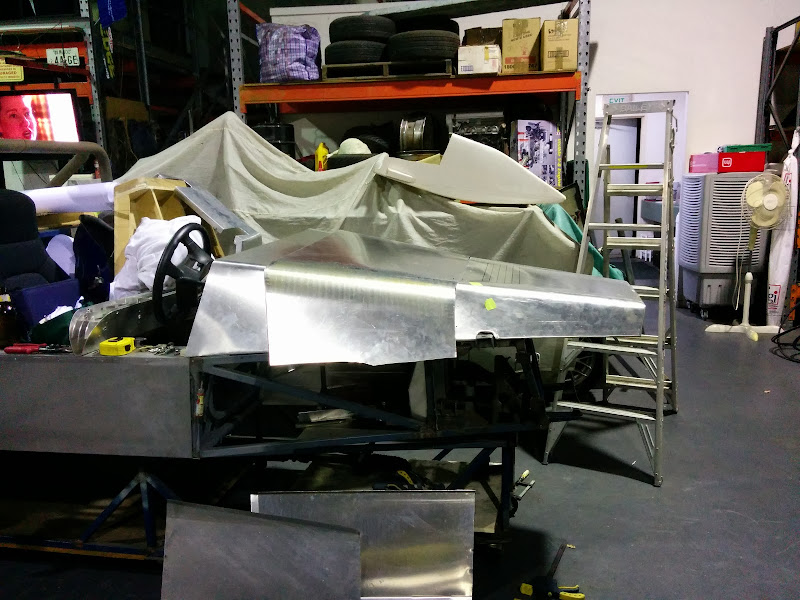
After a long hiatus due to family and health issues I've finally been making some visible progress on the Mk2 chassis (Mk1 got cut into bits, the
longer of which are becoming braces in Mk2 )
It's still going slowly but it is progress. Some pics are in my Picasa gallery
(linky) which also gives some sense of the design to put the photos in some context.
The last 4 photos are new today.
It's still a long (long, long) way from being finished but I feel more confident that I might finish it before I retire
Dominic
Ivan - 28/1/08 at 10:15 AM
I like what you're doing. Keep us informed of progress.
Was there any specific reason for the double top rail or is it just for side intrusion?
nitram38 - 28/1/08 at 10:26 AM
quote:Originally posted by Ivan
I like what you're doing. Keep us informed of progress.
Was there any specific reason for the double top rail or is it just for side intrusion?
Might be for a right hand shift?
TheGecko - 28/1/08 at 10:26 AM
quote:Originally posted by Ivan
Was there any specific reason for the double top rail or is it just for side intrusion?
The double top rail has been included in every version of my design, originally with the dual goals of torsion and beaming strength and some side
impact. The strength issue is important because I don't have a structural tunnel like a Locost. Strength is also the driver behind the
"portal frame" dashboard ring which the double rail design lends itself to very easily.
A side effect of the double rails is that the waistline of the body is outboard of the floor plan by 75mm. This gives a visual break which reduces
apparent slab sidedness that could otherwise arise with a mid-engine clubman shape.
As yet another side effect it should also give me more elbow room with side-screens fitted.
Edited to add reply to Nitrams question: No, the gear shift will be central. There'll be a small non-structural tunnel to carry water pipes and
the gear shift cables.
Dominic
[Edited on 28/1/2008 by TheGecko]
Ivan - 28/1/08 at 10:38 AM
Makes sense given that there is no real tunnel - thanks
RazMan - 28/1/08 at 12:49 PM
I am going to follow your project with great interest - looks really good so far.
sgraber - 28/1/08 at 04:45 PM
I am very happy to hear that the Gecko project is back on track!
More power to the Middies!
Graber
Fred W B - 28/1/08 at 06:44 PM
As above.......
Great to see you making progress.
Cheers
Fred W B
kb58 - 28/1/08 at 08:53 PM
I'm working along similar lines and want to also use high side tubes. My concern is that in even a mild side impact, the driver's head will
whip sideways and smack the very tubes designed to protect. I'm still working this out.
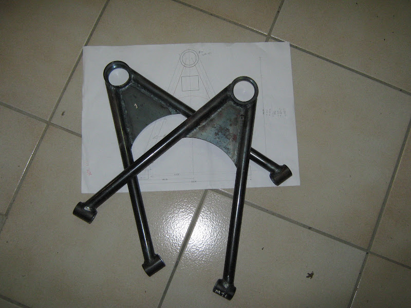
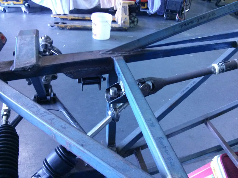
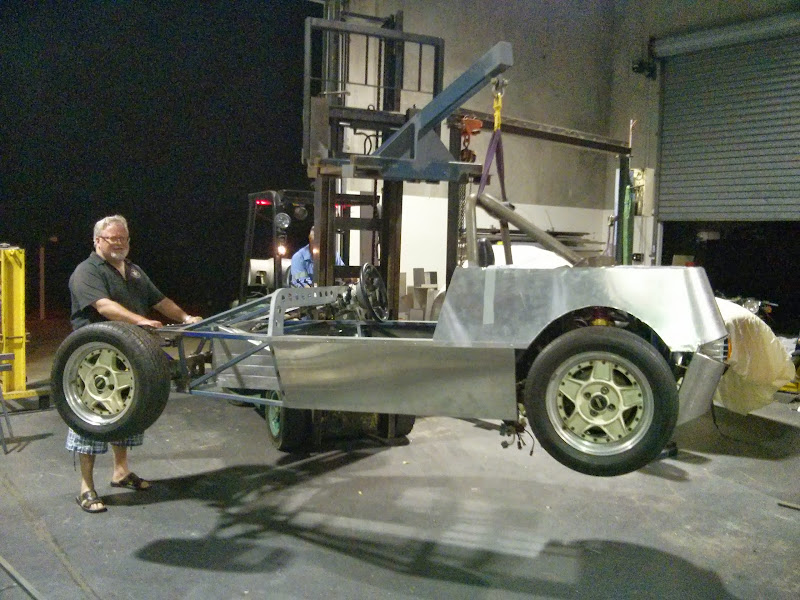
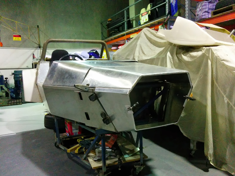
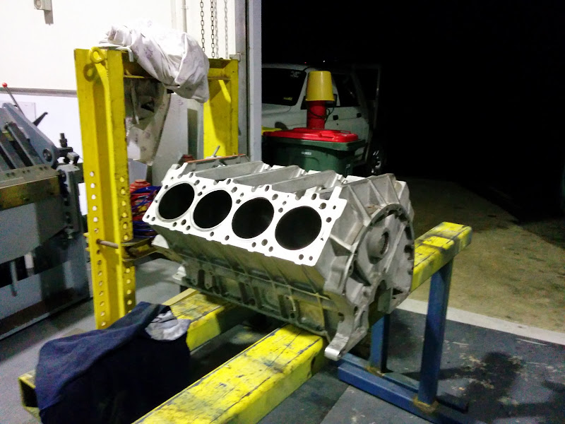
Wow, doesn't 6 months go past in a rush! Good thing I haven't set myself a deadline, I'd just be upset at myself. Since the last update
I've added some more tubes to the chassis and done quite a bit a fiddling with steering column positions relative to seats etc. The main activity
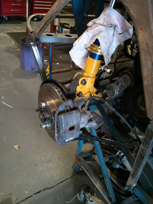
has been finally choosing and buying the Koni 8611-1257 double-adjustable strut inserts for the rear suspension. With them finally pinned down, I
could finish the layout of the strut tops and give the dimensions to my machinist friend for the manufacture of the spherical bearing plates with
integral camber adjusters. The alloy bits need to go to the anodisers yet but it's still worth a look at his work Here's all the
components of one assembly, including the spherical bearing and its retainer circlip, plus the pair of top hat bushes and retainer nut, all custom
made to suit.
And here's one assembled and in the strut tube which will be welded into the chassis.
This is the original AE101 Corolla housings with the big factory spring seats ground off:
And here they are back from having ~40mm taken out of the length and a piece of seamless welded on as a joiner and lip for the threaded sleeve:
And just to finish them off, a quick squirt of paint. Shows how close to tolerances Paul works - a few coats of paint and one of the sleeves is now a
firm press fit rather than slip on.
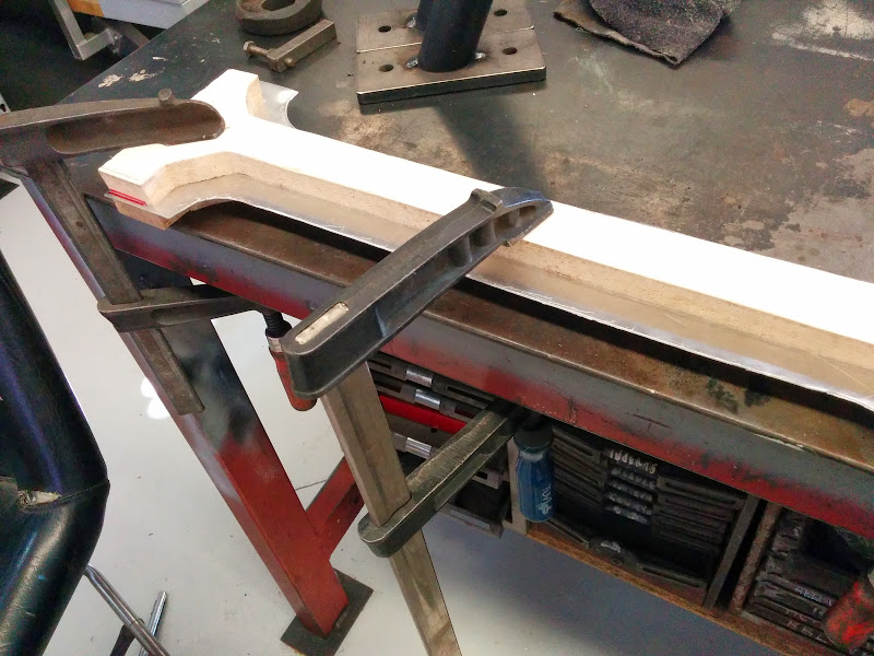
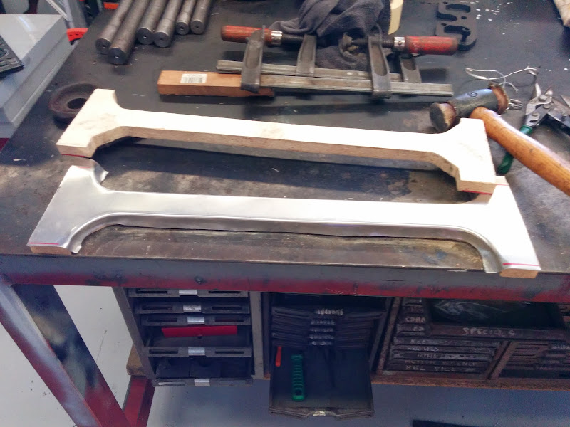
Over the weekend I finished the jig I'd been fiddling and fussing over to hold the strut tubes and the engine bay top rails all in the proper
alignment for welding. Complicated by the fact that the strut tubes are installed at a 5.3 degree angle to the rails to allow maximum travel on the
strut top bearing. Here's one side in the jig after tacking:
and the two sides finished:
Tonight I jigged everything together with bits of timber and lots of F-clamps (clubman builders can never have too many F-clamps ) and checked the
alignment of it all prior to welding.
And here it is with them welded in and some "masking tape CAD" to show where the two braces go in each side of the bay. I'll cut and
weld them tomorrow night (all things being equal).
A little every night if I can and I may get this done yet
Oh yesss! This is very exciting Dominic to see those rear suspension pieces come together. I look forward to the day that you have this thing sitting
on the ground on it's own suspension. That is a real milestone!
Geoff011 - 21/7/08 at 09:54 PM
Looking good Dominic! Keep at it!
Alan B - 21/7/08 at 11:55 PM
I like the adjustable strut top....should work well.
Alan
TheGecko - 8/3/09 at 01:44 PM
As always, no updates for quite a while. I'll combine a couple of sets of updates together here.
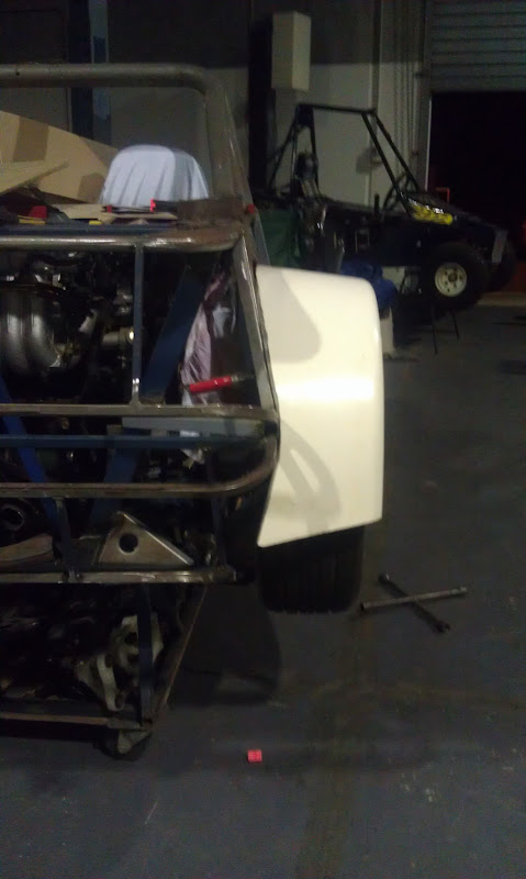
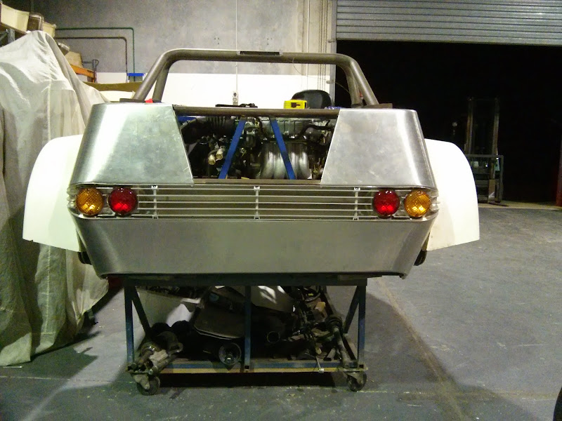
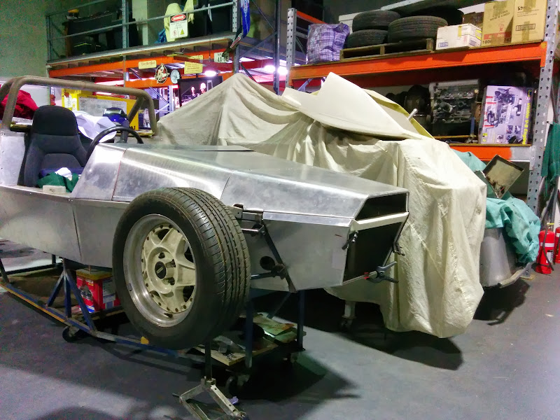
I swung the engine in for a little visit to its future home:
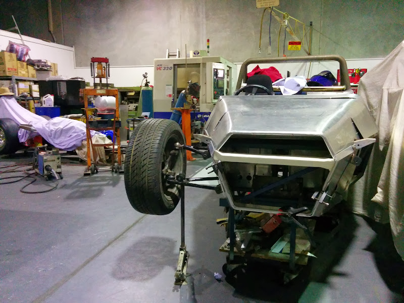
I got the rear suspension struts together and hung a wheel on the chassis:
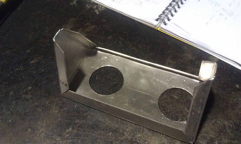
And, the clever hands of a machinist friend made me a nice little tool to put flared edges on the lightening holes in my dash webs.
These are the two stiffening webs to go on the scuttle bulkhead ring. 1mm steel, 35mm lightening holes flanged with the tool shown above.
Had a few stabs at the spacing first:
Then cut the holes and flanged them (after giving the whole thing a going over with a flap wheel in the Angry Grinder to clean off the rust etc):
Did the little one that sits the other side of the column as well. Only 4 holes in it:
Now I need to make the two webs for the bottom half of the bulkhead but they are (or should be) symmetrical so hopefully that'll go a bit
quicker.
More in the next post,
Dominic
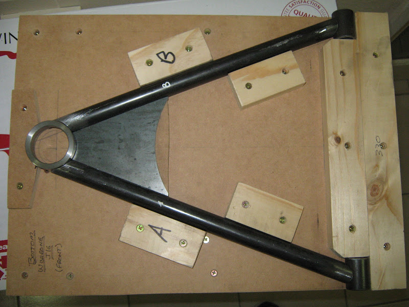
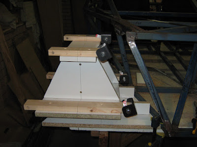
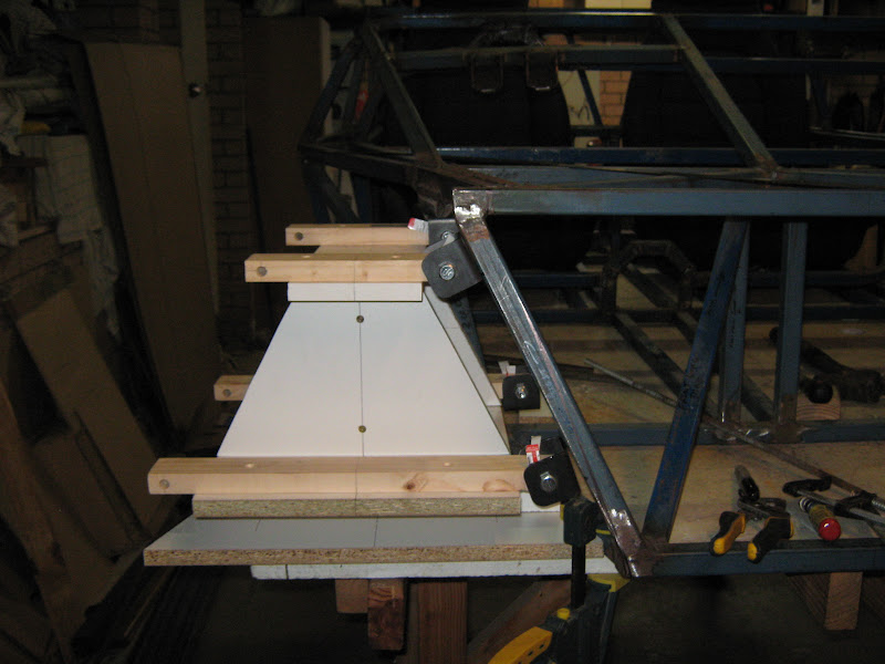
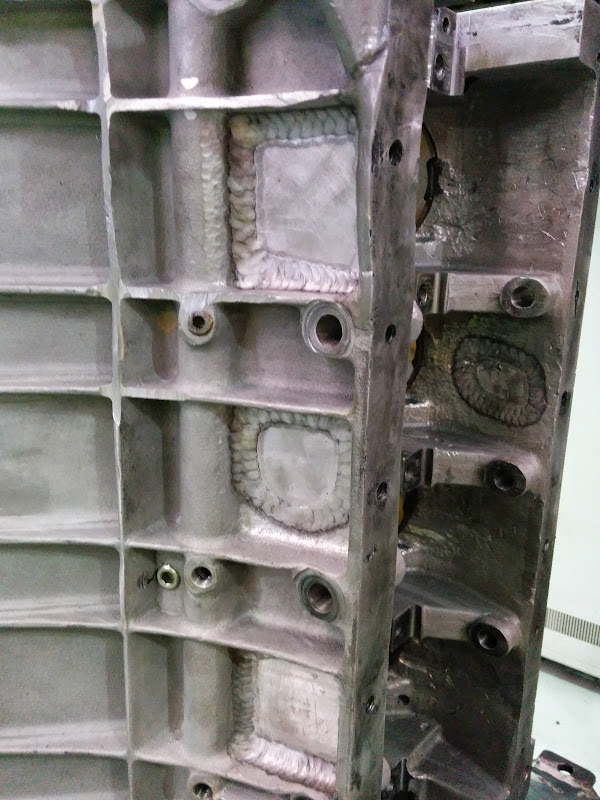
TheGecko - 8/3/09 at 01:47 PM
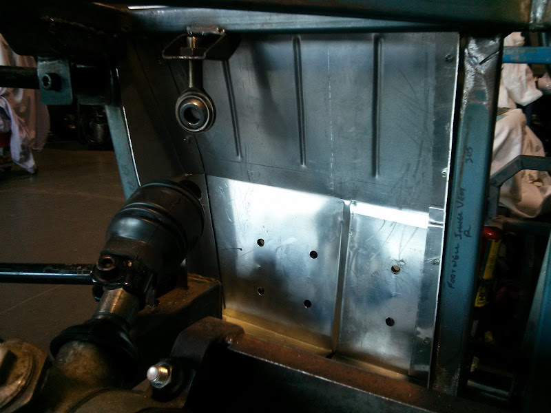
The Parable of the Plates
In the month of February an angel visited Dominic, giving to him several shining metal plates. And great was the beauty of these plates for they had
been cut not by human hands but by the artificers of Sea-En-Sea. And Dominic did gaze upon the plates and knew that they were good for they had been
made to The Plan.
Six were the plates in number but only three in shape for they had been made in pairs. And clear from their shape was their destiny. This destiny was
to be permanently joined to the Bay of the Engine, thence to work tirelessly at support and bracing.
And Dominic held the plates to the chassis, even though it still remains partial and unformed as it has been, and will be, eternally. And the plates
did fit - verily, so close was the fit that he did exclaim, saying "That's pretty snug. You couldn't get a fanny hair in that
gap". And great was his pleasure at this fitting.
And then he didst say to himself "Bugger, how am I going to drill 16mm holes in alignment when the tubes are already welded into the
chassis". And his disappointment at this poor planning was much. But, familiar with pain and struggle in the service of the revered Clubman, he
didst regather himself and cogitated for some time. And this cogitation was helped by the application of soothing waters bearing the Holy names
Shiraz and Cabernet Sauvignon. And the cogitation did bear fruit and he awakened saying "The bloody plate can be it's own drill
guide".
So he did clamp the plates firmly and many were the checkings of alignment. And then applied to them did he the 16mm holesaw and great was his fear,
saying aloud, "If I f*ck this up, there'll be all kinds of trouble". But the soothing waters had steadied his hand and the drill ran
true. And at last the holes were complete and wide was the distribution of coolant from the drilling.
And he rested from this labour, saying "Now I just need to weld the crush tubes, and then the plates, then finish the rest of the rear brace, and
the other set of side tubes, and the pedal box brackets, and the other column mount, and......". So great was this list of incomplete things
that he was rendered insensible and thus did his wife find him, staring at the wall and muttering. And she didst guide him away and render more
soothing waters until he did sleep.
Seriously (?!), a mate CNC cut these plates from my MDF templates and, after a couple of test iterations in acrylic, the steel ones are now lined up
ready for welding. My friendly machinist made me some nice little crush tubes and the whole shebang will give me a very solid but removable back edge
for the engine bay. And, if I ever stop working 60+ hours a week, I might actually find time to weld it all together.
Dominic
cheapracer - 9/3/09 at 05:23 AM
i do the strut tops a different way Dominic, I make up some suspension bushes using 32mm tube (fitted with suspension bushes) that i weld to some
fanges I make with an internal thread for the strut insert as per the picture...
I simply use some typical shock mounting brackets and overdrill the strut to upright mounting holes for camber adjustment.
Rescued attachment strut top.JPG
TheGecko - 9/3/09 at 07:10 AM
quote:Originally posted by cheapracer
i do the strut tops a different way Dominic, I make up some suspension bushes using 32mm tube (fitted with suspension bushes) that i weld to some
fanges I make with an internal thread for the strut insert as per the picture...
I simply use some typical shock mounting brackets and overdrill the strut to upright mounting holes for camber adjustment.
I had thought of a similar arrangement but the 2-way adjustable Koni inserts I'm using have the bump adjustment poking out of the threaded end of
the strut, so that put an end to that idea. I toyed with the idea of offsetting the mount from the strut shaft but ended up going the way I have,
partly because I have access to a friendly, competent machinist to make shiny parts for me
Dominic
GRRR - 9/3/09 at 08:53 PM
Impressive work going on there! Quick and probably daft question on those struts, when the car is sitting on the ground, the strut body will push
against the spring via the threaded sleeve; is the threaded sleeve welded on or is it that bit of larger diameter seamless butting up against it?
TheGecko - 9/3/09 at 10:47 PM
The threaded sleeves are universal aftermarket ones for conversion of struts to adjustable coils. They're alloy so, no, they aren't welded
to the steel body - they bear on the larger diameter piece (which is also there to join the strut tube where it had ~50mm of length removed).
Dominic
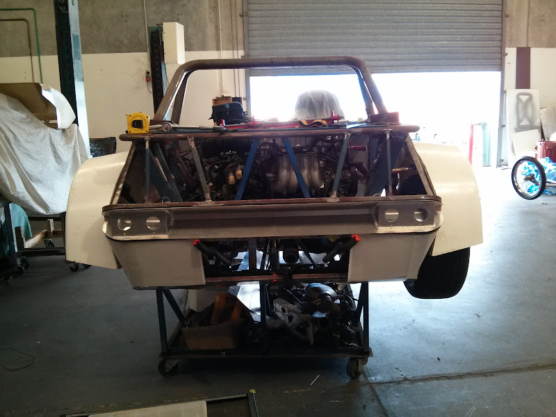
TheGecko - 4/5/09 at 07:41 AM
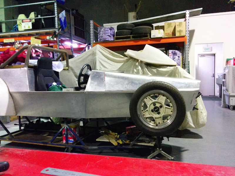
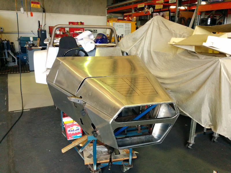
My welder friend is pushing me to make progress so he came over yesterday and we got a lot of welding done on the chassis. After he'd left I was
cleaning up and decide to pull the chassis off the build board onto the floor and prop it up at ride height for a look see. Definitely starting to
resemble a car now
There's still quite a bit to do but some things I'd held off finishing until internal corners were welded can now be done. Plus, we
didn't flip the chassis over so there's still all the underneath joints to do. Anyway, any progress is still progress.
Dominic
cheapracer - 7/5/09 at 03:21 PM
Great feeling when you can actually see something for the first time!
Well done Mate ;-)
TheGecko - 23/4/10 at 12:24 PM
Scary! - nearly 12 months since my last update
Work has been eating me alive for the last year, to the point of asking (demanding!) that I cancel my leave last year in favour of a project with
impossible delivery dates. Leave was canceled and then the project got deferred anyway
So, we finally got to take some leave and we're just coming to the end of 6 weeks off (back to work Tuesday ). First two weeks spent out of
town having a proper holiday together. Next two weeks mostly spent running to-and-fro with family matters (a seriously ill father). By week five,
energy levels were rising enough to consider work so some of the crap in workshop was reorganised (meaning, I moved it from one pile into another) and
I tried to get the chassis out to work on.
Job one was replace the castor wheel I'd broken off the build table when I shoved it in the corner. That means, drag chassis off board onto floor
[took the opportunity to put the chassis on the scales and pleasantly surprised to see ~85kg], then drag build board off base onto another piece of
floor, then flip base upside down onto build board and drill the screw holes for the castor to the right depth this time. Standing looking at the
caster, getting measurements, SWMBO enters workshop and sees me in flip-flops(*note) - says "Are you putting your safety boots on?".
"Yes dear, once I actually start working on things". Put castor down, only to have it overbalance, and fall from bench height onto big toe
nail Cue mixture of concern and pissing-herself -laughter from SWMBO as I roll on floor clutching toe!
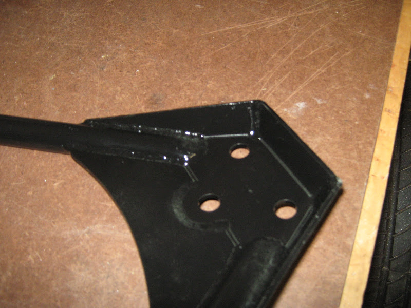
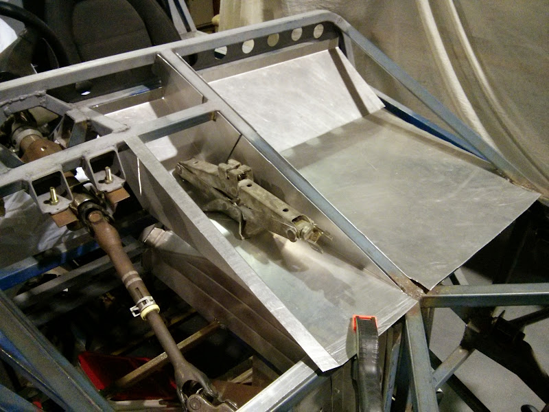
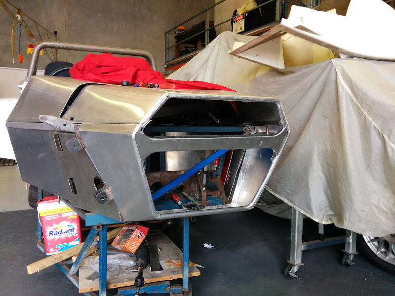
Anyway, self harm aside, while the chassis was on the floor, I propped it up ride height and finally finished the removable rear engine bay brace.
This means I can swing the engine in and finalise engine mounts etc. And here's a picture
Engine bay from behind with the brace in
And with the brace removed, showing ease of access
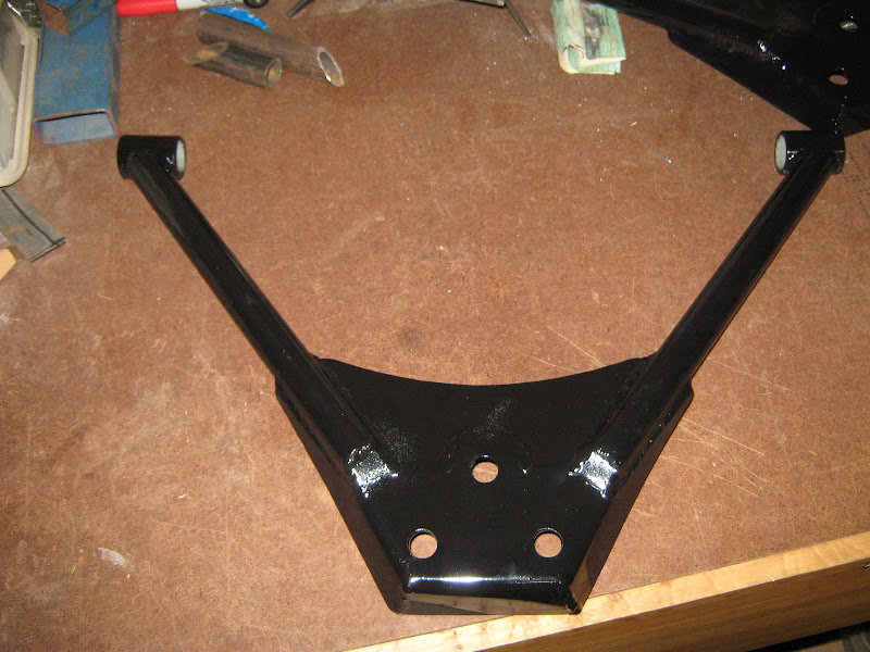
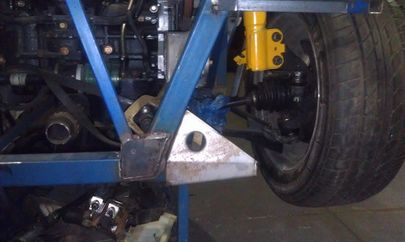
The welded in mounting plate also gussets the strut tube. A "matching" plate is welded to the top of the brace.
On the subject of engine mounts - I'm interested in opinions one way or the other regarding reusing the OEM Mitsubishi mounts versus the
"universal" type machinery mounts that most people seem to use. Given that they're acting as both engine and gearbox mounts I'm
wondering if the universal ones are appropriate or not? Answers on the back of a $50 note to the undersigned
Anyway, any progress is good so, onward and upward.
Dominic
(*note - In Australian English I would say "thongs" - I'm hoping flip-flops is correct British English)
RazMan - 23/4/10 at 01:04 PM
Nice to see that you are making some more progress Dominic.
p.s. English for thong = something like Borat Mankini
kb58 - 23/4/10 at 03:04 PM
quote:Originally posted by TheGecko
... Standing looking at the caster, getting measurements, SWMBO enters workshop and sees me in flip-flops(*note) - says "Are you putting your
safety boots on?". "Yes dear, once I actually start working on things". Put castor down, only to have it overbalance, and fall from
bench height onto big toe nail .
Reminds me of the line from the movie, The Matrix: "Don't worry about the vase." If she hadn't said anything...
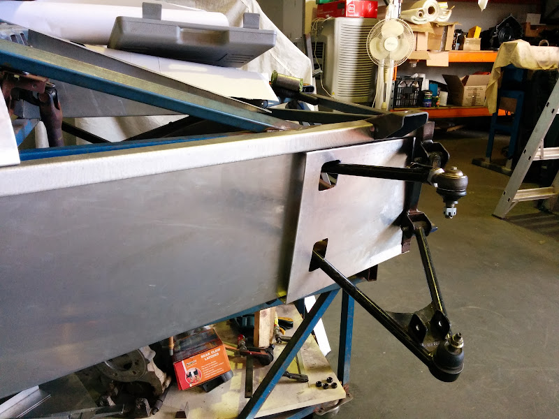
TheGecko - 11/5/10 at 01:09 PM
Suspension work continues apace.
On the weekend my machinist friend handed me a box with my top wishbone threaded bushes - these are the "infinite adjustment" type with a
threaded sleeve inside the weld tube - see photo. No excuses not to get my wishbones finished now Thanks again Paul.
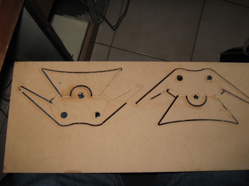
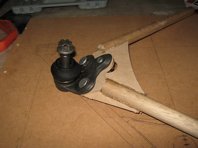
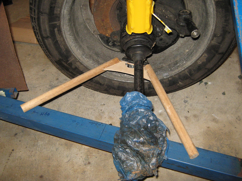
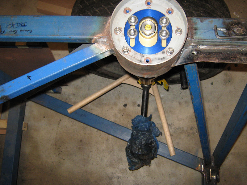
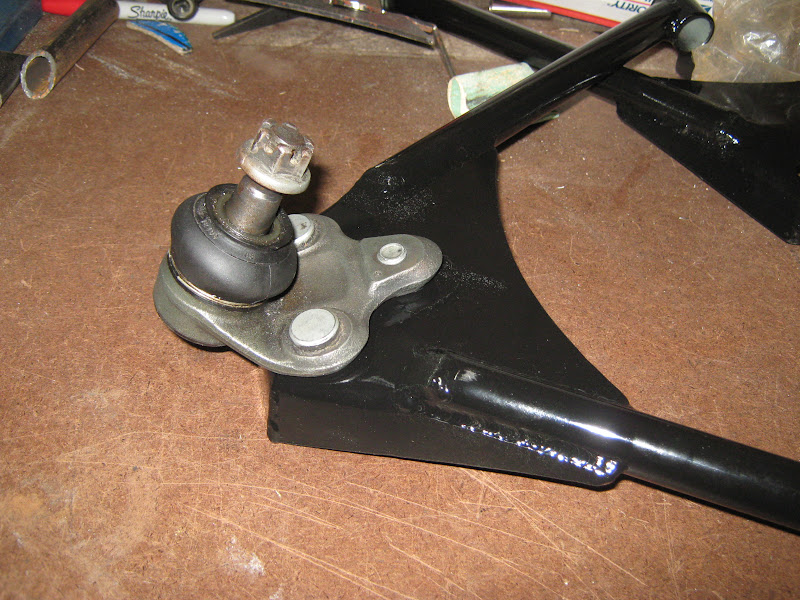
The rear end of the car is strut by Corolla uprights and modified strut tubes. The Corolla bottom balljoint is an odd shape (a little reminiscent of
the angled Cortina lower part) and I'd spent a bit of time fussing around how I'd mount it. Last night I picked up this from my engraver
friend:
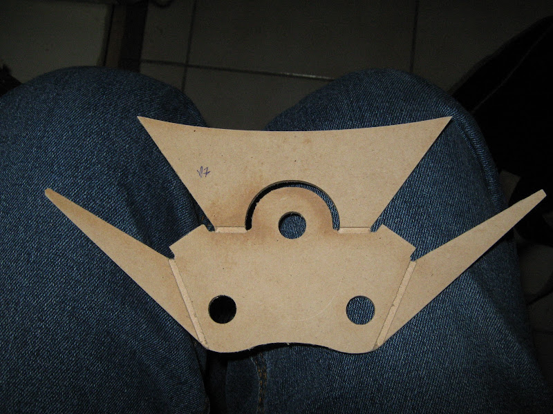
Two sample wishbone plates, test cut in 3mm MDF. Once knocked out and cleaned you get this. Note the half depth slots - these are to encourage and
assist some bends.
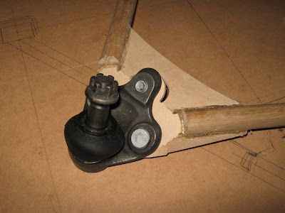
Once bent and hot-glued to some 22mm dowel "wishbone tubes" you get this:
And here's the mock-up wishbone in place with the upright etc to check clearances:
There's a few small tweaks needed but it looks like I can get the real deal cut in 3mm steel sometime early next week. Should be able to tack up
top front and rear wishbones all at once
Dominic
cheapracer - 23/5/10 at 01:47 PM
Dom you understand if you run your exhaust too close to those wooden arms that they will catch on fire?
Not that thats a problem but the fire will surely melt that very thin plastic CV boot THEN you will be in the shit.
TheGecko - 24/5/10 at 09:38 PM
Thanks for that advice Mark. It's this sort of insightful, helpful advice that keeps me coming back here
Dominic
Benonymous - 8/6/10 at 07:24 AM
What about when it rains????
MDF just swells up and disintegrates!!
If you'll take my sage advice, you'll switch to oak for those components or spruce if you desire light weight.
ceebmoj - 9/6/10 at 08:23 AM
why did wooden cars fall out of favour? the early marcos where wood construction and im sure there where others.
iank - 9/6/10 at 08:33 AM
quote:Originally posted by ceebmoj
why did wooden cars fall out of favour? the early marcos where wood construction and im sure there where others.
Morgan still have an ash frame supporting the body.
I think the workmanship and time required for a wood frame is a lot more than that required to mig together some tube.
TheGecko - 9/6/10 at 10:39 PM
I'm hoping that everyone is just gently taking the p*ss here. However, just to re-iterate and to avoid any misconceptions - these are purely
mock-up parts made to check the fold angles of the ball-joint plate etc.
The finished product will be made of steel.
Dominic
rick q - 10/6/10 at 03:27 AM
quote:
The finished product will be made of steel.
Risky choice Dominic - steel rusts.
A few decent coats of quality spar varnish on the MDF will make it a much better choice than steel!
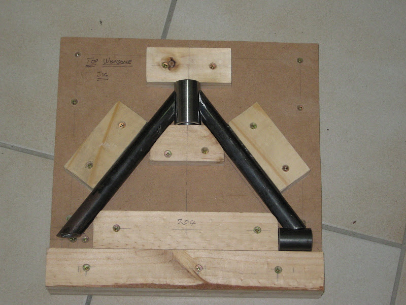
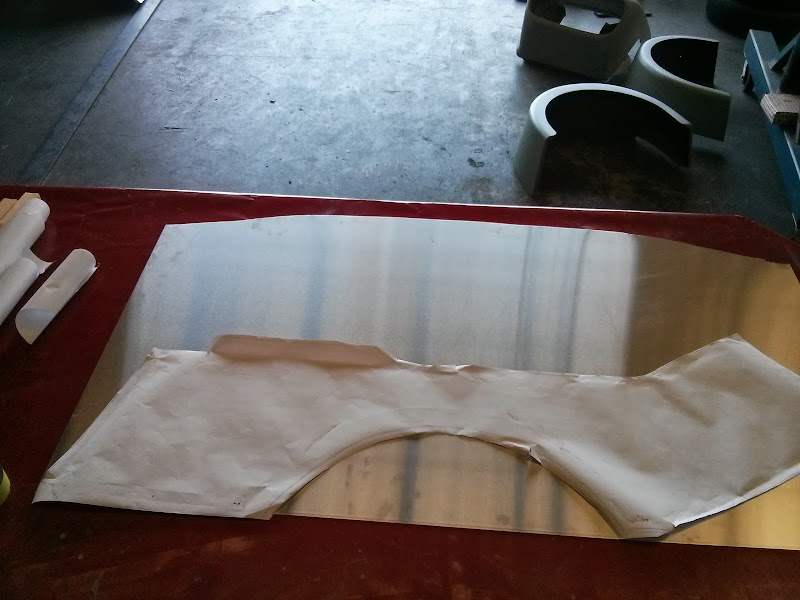
TheGecko - 18/3/11 at 01:46 PM
Following some nudges by another member here (Hi John), I'll add a quick status update.
Front wishbones are done (top and bottom)
I made a two-part jig to align the wishbone brackets to the chassis (double sided so I use it for left and right)
The bottom part can slide fore and aft along the chassis for one part of the alignment while the top half slides in and out to offer up the brackets
to the chassis. And here's a picture of the brackets ready for tacking.
Because the shape of my car isn't really like a Locost in terms of angles etc, there's no easy way to make a "standard" nosecone
fit. I got a spare fibreglass nosecone from a mate and looked at splitting and re-joining it but couldn't see it turning out well.
Inspired by John's (member 2cv) posts on metal shaping (see more in this
thread), I've decided to have a crack at making one in aluminium. Here's the quick Sketchup model I drew quite a while ago to get a
sense of the basic shape, which is almost all single curvature.
And here's the current state (pretty much) of the buck I'm building to form the nosecone over.
I've got 4-weeks of leave coming up soon (in three weeks today actually!) to work on the car - SWMBO is only off work for the last 4 days of it.
The intent, by the end of that time, is to get the car to:
chassis fully welded, including all brackets etc (95% done already anyway)
suspension all fitted and car on the ground on its wheels (front is mostly done - rear remains to complete)
all major fixed panels fitted (i.e. firewall, floor pan, sides etc)
brakes & clutch plumbed
chassis structural tests completed (required for registration here - full torsion & beam strength tests)
engine mounted and plumbed (but probably not wired - dealing with the horrifying loom may need 4 weeks all on it's own!)
Expect some more updates soon.
Dominic
cheapracer - 22/3/11 at 12:45 PM
Dominic, will you be using a resin or lacquer to protect the wood from the elements?
Sump oil, although harder to clean bugs off and a bit smelly, would be locost.
TheGecko - 23/3/11 at 07:00 AM
quote:Originally posted by cheapracer
Dominic, will you be using a resin or lacquer to protect the wood from the elements?
Sump oil, although harder to clean bugs off and a bit smelly, would be locost.
I was going to go "old school" actually and use left-over house-paint. I've got a half-tin of "Hazel Mist" semi-gloss
acrylic that should look quite nice.
As always, thanks for your helpful and constructive input
Dominic
2cv - 23/3/11 at 08:38 AM
Thanks for the update Dominic, excellent work. I'm looking forward to seeing pics of the next bit. Do hope you enjoy your break from work and
that you can get on with the important stuff!!
John
TheGecko - 23/3/11 at 01:15 PM
Small update since I actually got home early enough to get into the workshop (for a little while at least).
First part of the nose profile piece for the nosecone buck. Photo 1 is before running across the router table to put inside and outside radii on it
(6.35mm and 12.7mm respectively). Photo 2 is after (duh!).
Still need to finish some of the intermediate braces in the buck (it needs to strong if I'm intending to hammer on it at all!) and make the
bottom part of the profile.
2-and-a-bit weeks till I'm on leave. Lots of things to get organised before then
Dominic
cheapracer - 30/3/11 at 06:19 PM
quote:Originally posted by TheGecko
As always, thanks for your helpful and constructive input
Dominic
he he - take the bit of fun as a compliment, not much to criticize on your build, well done!
TheGecko - 5/4/11 at 11:48 AM
Some updates - got to a final design for the rear wishbone balljoint plates. Here they are CNC cut with slight grooves to assist vise bending; and
one folded and bolted into the wishbone jig.
Final product all TIG welded then painted; showing the underside of the folded part; and with the ball joint mounted.
Holidays start this weekend - lots to do!! More updates soon.
Dominic
SeaBass - 5/4/11 at 12:11 PM
Wont' your lower wishbone be almost parrallel to the ground? If so that bottom ball joint will be at a really odd angle to the upright? The
balljoint stub wouldn't be central and therefore risk binding? What thickness is that plate?
[Edited on 5/4/11 by SeaBass]
TheGecko - 5/4/11 at 12:18 PM
All good questions SeaBass
The wishbone will actually be downhill to the ball joint at normal ride height, because the rail the brackets are going on puts the pivots about 200mm
above ground level.
The balljoint is at an odd angle but that's because the hole in the upright is too - it points at the top of the strut, not vertically. Found
that out the hard way when the original plate design put the balljoint shaft vertical and then realised they would've run out of motion in droop
The plate is 3.5mm-ish - I suspect it's actually badly toleranced 1/8". I got a 600x1200 sheet of it for a few dollars scrap value and
it's served me well for all of my various brackets.
Dominic
[Edited on 5/4/2011 by TheGecko]
2cv - 12/4/11 at 06:29 AM
There's some really nice work gone into those wishbones Dominic; very impressive, neat folding on what is quite thick material. I particularly
like the little tabs that act as tube stops. Keep the pictures coming please.
[Edited on 12/4/11 by 2cv]
TheGecko - 12/4/11 at 07:20 AM
Thanks John, I'm very happy with how the wishbones turned out. The steel was surprisingly easy to bend because the portions being bent were
relatively small and the rest of the plate gave me leverage. Plus, the very shallow (~0.5mm) slots "encouraged" a bend in the correct
place. Given the amount of metal and the final welded form I'm not worried about any lost strength from those slots.
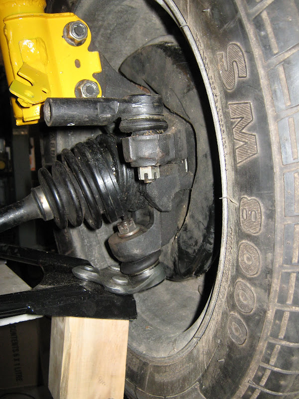
Just catching my breath the last few days after finally starting my leave so not much to show yet. However, I did bolt together one whole set of rear
suspension with the wishbone brackets clamped on the chassis to check. Very pleased to measure static camber at about 1 degree negative, with some
range in the strut adjustment to go further. That's what all of the design work said it should be but reality has a way of proving me
wrong sometimes Pic of the whole assembly below, plus another showing the inclined entry angle in the Corolla upright, explaining the
"odd" angle of the ball joint and wishbone.
Sometime in the next day or two I'll get the wishbone brackets welded to the chassis. Then I can drop the whole thing down on the floor and see
what I've got Next thing after that will be toe-links using the original tie-rod end as the outer (visible in the pics) and a spherical joint
as the inner end.
More updates as they happen....
Dominic
2cv - 12/4/11 at 11:14 AM
It's very satisfying when theory and practice agree and the great plan comes together. It really is looking very good; you must be delighted with
what you've achieved. Only another builder can appreciate the painstaking work that has gone into this build. Quality in every joint!
atb
John
TheGecko - 14/4/11 at 09:16 AM
Thanks for the kind remarks John.
A bit of progress today as a friend came round to help and managed to nudge me through my normal rounds of "Paralysis by Analysis" End
result - rear suspension brackets aligned and fully welded.
Plus, he helped me flip the chassis over so I could finish some of the underside welds. After they were done, I flipped it back and dragged it off the
build table and stuck some front suspension on too
Don't look too closely at the welding on those brackets. Need grinding out and redoing with the chassis at a more workable angle
More updates as they happen....
Dominic
TheGecko - 5/1/12 at 03:26 PM
Well, in the pursuit of some progress, the chassis has moved to a friend's workshop where I have access to better tools but more importantly his
much better expertise which will hopefully nip any "analysis paralysis" issues in the bud. There's plenty going on in his shop already
- and there's another car behind were I was standing too!
D
rowlocks - 13/1/12 at 11:20 PM
Hi,
Awesome project! Just a question about your rear suspension,
What shocks are you using? Are they designed to be used for macpherson struts? A macpherson strut would place greater side loads on the shock wouldnt
it? Also will you have a handbrake?
TheGecko - 14/1/12 at 11:48 AM
Hi rowlocks,
The strut inserts I'm using are specific parts for Macpherson struts, not some generic shock absorber. You can see one of them in my post from
21 Jul 2008. Note how thick the shaft is compared to a normal shock? That's to deal with side loads.
Handbrake - I'm using Corolla AE101 front uprights and discs but replacing the calipers with XF Falcon rears which are: the right width, have a
handbrake mechanism, and are alloy so quite light.
Hope this helps,
Dominic
TheGecko - 29/1/12 at 12:43 PM
Have had a couple of bursts of productivity over the last few weeks.
Mocked up the position of the inner toe-link mounts at the rear. Used the engine hoist to run the suspension up and down through full travel while
checking bump steer. Waiting on some LH female rod ends to arrive now. Will add some pics of the final bracket and adjuster once they're
done.
Today was rack positioning. After some faffing about, took the 9" grinder to a pair of diagonal tubes that were in the way Made things much
easier after that. Stuck some temporary rails under the rack and fiddled with various packing pieces until the right position was established. With
a small laser pointer strapped to the stub axle (pointing out to the side) total bump steer (all toe-in) was 5mm measured at 3.6m away. That'll
do alright Next step is to mount the column again and find the correct rack angle, then make permanent mounts.
Dominic
TheGecko - 11/2/12 at 09:50 AM
A few quick updates:
- made some rack mounts from bent 20x3mm with 1.6mm sheet stiffening webs
Looks like Gemini (Chevette) and Escort racks share basically identical mounting dimensions so quick-rack upgrades should be a relative doddle
- today, cleaned up the remains of the cut-off diagonal tubes, fitted the two 20mm cross rails, and made a stiffening web to tie the two rack
brackets together. Dry fitted for now, will post another shot without the rack once it's all welded up.
Dominic
John Bonnett - 11/2/12 at 03:26 PM
Hi Dominic,
Good to see your progress and work of the highest quality. I've been fairly quiet on this Forum for a while as I am restoring a Triumph GT6 but I
keep an avid eye open for news of your project. Please keep the pics coming. Your thread is a fascinating read.
Best regards
John
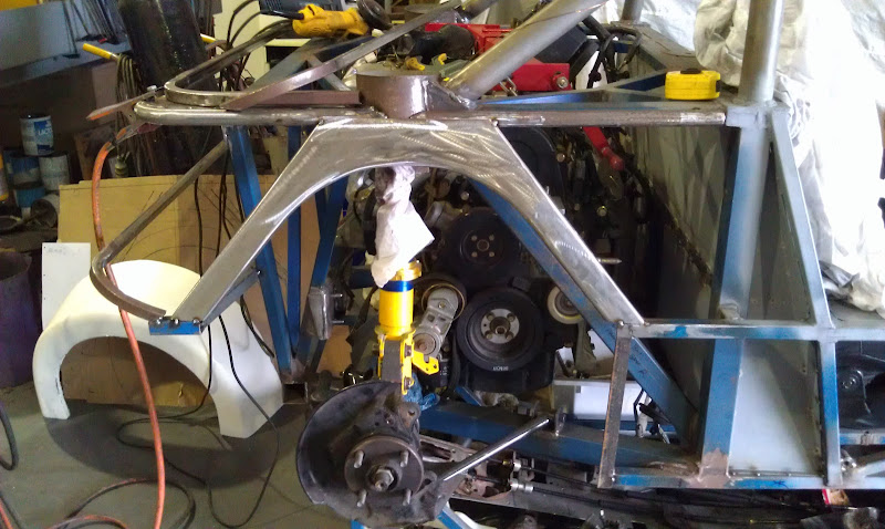
TheGecko - 17/3/12 at 02:05 PM
Haven't posted an update for a while, so.....
Finished welding up the rack mount in the bench and spent a fair bit of time getting it properly positioned in the chassis before welding it in. Some
finish welding to do once the chasis is flipped into a more accessible position. End result is stiff and light.
Progress has slowed because the semester has started and work pressures ramped up accordingly. Still, have managed to twiddle around with engine
mounts and got to this point....
That's it sitting/hanging on the four tacked in mounts Everything was put together with the drivetrain centred (i.e. equal length
driveshafts). Now that it's in, it's readily apparent that it can/should go left quite a bit. So, this weekend I'll pull the engine,
knock off the tacked mounts and shift everything left a few inches. Will make for a much happier level of access around the accessory end of the
motor. If I don't do it, it'll just wee me off forever more
More as it happens...
Dominic
TheGecko - 18/3/12 at 09:35 AM
OK, knocked all the mounts off the chassis, shifted the front and rear ones to the left by ~70mm, remade the left and right mounts to suit. Done.
Pedals are next....
TheGecko - 7/5/12 at 08:39 AM
Realised I hadn't posted some recent updates here.
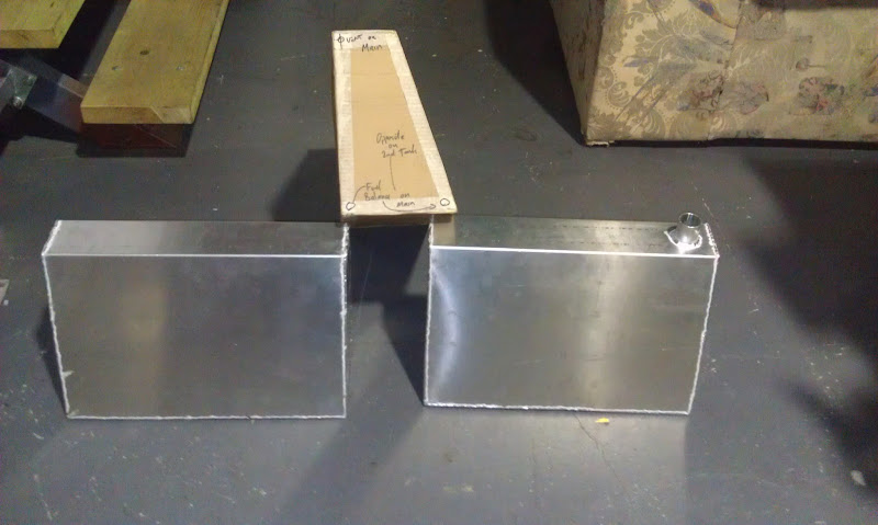
Fuel tanks are made by my friendly fabricator. Here they are side by side with the CAD (Cardboard Aided Design ) prototype.
This is the two inner ends showing the various balance, feed, vapour etc lines top and bottom.
And here they are in the chassis:
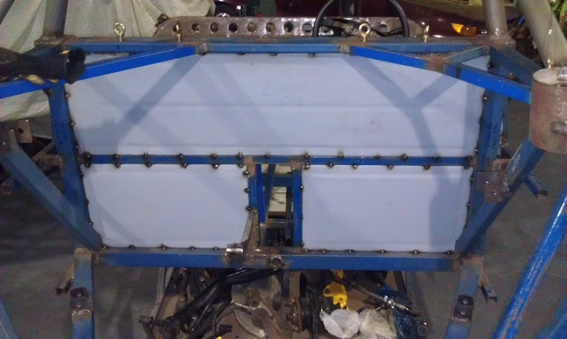
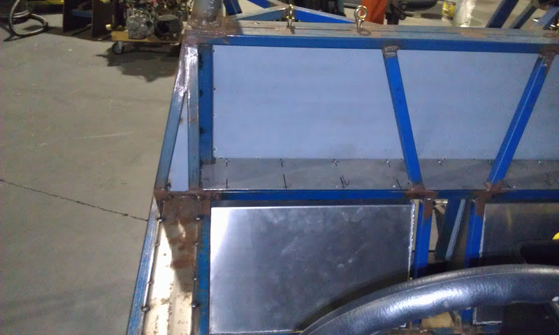
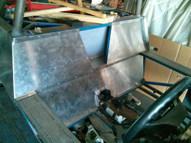
Also, finally got the firewall panels welded in. I originally thought about full seam welding but they're probably just going to get a bead of
Sikaflex/seam-sealer both sides and then painted over. Second photo shows them from the front and a little of the arm-rest/sill fill panels taht are
also welded in now.
Pretty much ready for the chassis torsional strength tests now Bit of a make or break moment that!
More as it happens.
Dominic
[Edited on 7/5/2012 by TheGecko]
andyd - 10/5/12 at 08:48 AM
Nice stuff Dominic.
Q.
How do you intend to test the torsional strength?
Clamp three "corners" and jack up the fourth with a strain gauge attached?
If so, what figure would you be looking for and how did you decide on that figure?
I'm just curious as to what you believe is good (or good enough) and how you'd go about finding out.
I'm still in virtual land with my design but I'm always looking to learn
Fred W B - 10/5/12 at 09:49 AM
I have the below list of several figures, obtained from various sources on the internet, particularly contributors to www.locostbuilders.co.uk
Because the test is a required part of the engineering certification there is a formalised test process. This involves restraining the rear end of
the car (through the hubs) and applying torsional stress through a beam attached through the front hubs. Obviously, all shocks & springs are
replaced with rigid spacers for the test. Here's a photo of someone elses frame on a torsion jig:
The beam is loaded up with weights, either steel or concrete blocks (what our North American friends would call "cinder blocks" but always
known by the trade name "Besser block" in Australia), and displacements measured at the dial guages down the side. Allowance is made for
deformation of suspension bushes etc by measuring the deflection at the rear axle line (theoretically nil) and subtracting that from the other
values.
In terms of actual values, local registration requirements mean I need to get at least 3600 Nm/degree (from memory) which is about 2650 ft-lb/degree.
As Fred's numbers show, a "stock" Locost chassis doesn't even get close . A recent test by a local builder of a modified
chassis returned around 8000 Nm Video of the test being performed can be seen
hereand here.
A beaming strength test is also required, where each seating position is loded with 160kgs and the beam deflection of the chassis measured. Maximum
is 1.25mm.
Thanks for the interest. I'll certainly be posting pics of the test process and my results once it's done.
Dominic
[Edited on 11/5/2012 by TheGecko]
andyd - 13/5/12 at 09:29 AM
Thanks Fred & Dominic for the info.
It looks like a good idea to stop people from just welding up a few bits of steel and driving off down the road
Not sure the UK officialdom would be able to cope with this being something that we'd have to do to pass our approval tests but as most of the
builders would value a good stiff chassis it would make sense for people to carry out the tests themselves even just for self satisfaction.
As my goal is a Lotus Elise'a'like, thanks to Fred's research, it looks like my chassis would have to go some to get close to the real
Elise numbers!
Good luck with the test Dominic. It'll be good to hear/see how you get on.
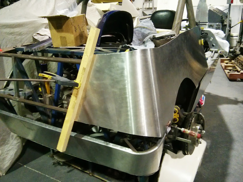
TheGecko - 26/7/12 at 10:54 AM
So, after a variety of delays, the fateful day arrived today
That's 285kg of concrete blocks and scrap steel loaded onto the beam for the torsion test and 140kg per seating position for the beaming strength
test.
I don't have the engineers report back yet but, based on the trial runs I did the night before, I believe it exceeds the required 3800Nm/degree
by quite a margin (possibly as much as 50% )
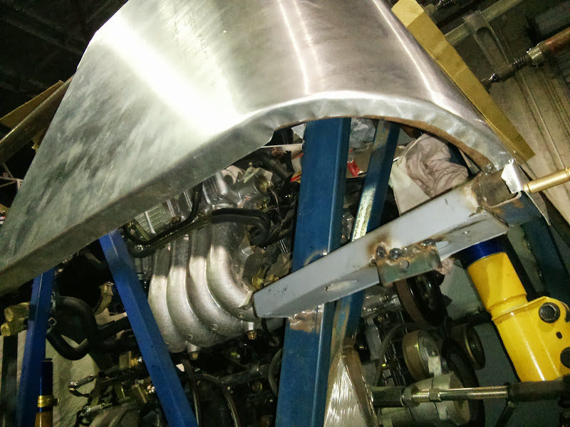
Can go to work on the tail end now with the various non-structural support tubes for the rear bodywork.
Dominic
iank - 26/7/12 at 05:32 PM
Well done on getting through that, it looks even more nerve jangling than standing next to a rolling road while the operator gives your new
engine 7500rpm!
TheGecko - 27/7/12 at 06:06 AM
Got a phone call from the engineer, who obviously knew I was sitting like an expectant father waiting for results 5828 Nm/degree will do OK His
remark? "You could put a V8 in that if you wanted!"
Happy as a dog with two tails right now.
Dominic
Report this post
Benonymous - 13/8/12 at 12:20 PM
Well done Dominic! Isn't it a pain what we have to go through to build our own car. Makes me very sad how shiny bums in the "public
service" sit around all day with nothing to do but dream up more laws to restrict peoples creativity and inventiveness.
I'm all for safety but what could be an accessible way to build something we really want has accumulated all this extra cost when the number of
individually constructed vehicles is minute in this country.
As a matter of interest, what do you think the ballpark cost of the engineering and approval will run you?
Doug68 - 14/8/12 at 10:40 AM
Yep, well done indeed!
TheGecko - 14/8/12 at 02:13 PM
quote:Originally posted by Benonymous
Well done Dominic! Isn't it a pain what we have to go through to build our own car. Makes me very sad how shiny bums in the "public
service" sit around all day with nothing to do but dream up more laws to restrict peoples creativity and inventiveness.
I'm all for safety but what could be an accessible way to build something we really want has accumulated all this extra cost when the number of
individually constructed vehicles is minute in this country.
As a matter of interest, what do you think the ballpark cost of the engineering and approval will run you?
Ben,
I'm kind of torn about the engineering requirements. In one way they're somewhat of a pain to meet but on the flip side they do help do
ensure the end result of my "back-of-the-envelope" doodling isn't a complete death trap
Re: costs - I still have a couple of tests to do once the car is driveable. Lane change stability and brake performance (both of which can no longer
be done on public roads so add in a track hire cost as well); drive by noise tests; and the final engineering submission to the Transport Department
for approval. All up I'll be surprised to have much change out of $1500-$2000 in engineering and associated costs.
Oh well, it's only money
Dominic
Benonymous - 15/8/12 at 12:30 AM
Thanks Dominic, that's very interesting. I know that state-by-state the laws change quite significantly in Aus and an ICV (Individually
Constructed Vehicle) that is registered in one state may not be eligible to be registered in another. I'm surprised at the relatively low cost
you've quoted, a bloke in NSW was telling me that he is expecting to fork out nearly $50K to get his ICV engineered, approved and registered! I
didn't know about the stability check either. I think the shiny bums are just going to keep inventing tests and adding costs until everyone just
gives up and buys a Holden.
Bastards.
TheGecko - 13/10/12 at 10:17 AM
Despite the absence of updates I have been busy on the car since the B&T. Here's a few updates....
Started fitting the various non-structural tubes that will support the rear bodywork.
Round corner pieces were "rescued" from a chair frame I saw in a skip at work. Seemed a shame to let those nice mandrel bent 25mm tubes go
to the tip A bit of a trim and a join to add a straight piece in the middle, plus a folded 1mm steel gusset plate in each corner.
Then added some bits to define the edges for the wheel arches and support the first of two mid-level tubes across the back.
Don't worry, there's a plan for what the rear will look like
Didn't really like the bits of 25mm angle I'd used for the wheel arch supports so I made a hammerform from various bits of timber....
..and formed up a 1-piece sheet metal part instead. This has folded edges both ways for stiffness.
Meanwhile, a pair of standard rear guards have been trimmed to fit over the side-shape of the bodywork. That trimming lost all of the flat mounting
flanges at the back so I need to glass in a new flange. To do that, I need a smooth form, the same profile as the final side shape of the car. Some
wood profile blocks plus a spare piece of cosmetically scruffy 1.6 ali plus some time with the 1200mm folder equals....
Still some tidying up to do on that one before glassing. Was hoping to get that finished this weeked but time has beaten me.
More in the next post....
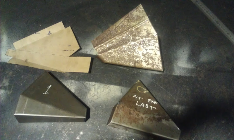
TheGecko - 13/10/12 at 10:23 AM
Amazing how much time can be spent on what seem like simple things. Because the car is in someone else's shed, across town, I have half-finished
bits of plans floating in my head all day that I then try to turn into actual parts in the workshop. At that point, the physical reality of the car
intercedes and stuffs up my plan A few nights ago I made one little(ish) bracket but made it three times (four, if you count the initial cardboard
template!). Managed to bend the first one on the wrong fold line (working on the back with incomplete marking), marked and cut the second one wrong
and didn't realise until the last two folds wouldn't work, finally got the third one right. Took a photo after Mr H helpfully labelled the
three versions for me
Then added one our my/our standard flanged lightening/stiffening holes, welded up all the internal corners, and gave it a test fit in its final home.
Now I just need to make a mirror image one for the left (which I have a 50:50 chance of screwing up ) and weld them in.
And even then, it's still not obvious to anyone what they're actually for Was also hoping to get enough done this weekend to make it
more apparent what's going on - will see how tomorrow goes.
Dominic
TheGecko - 13/10/12 at 10:24 AM
Teaser pic....
John Bonnett - 13/10/12 at 12:20 PM
Some really nice work there Dominic; very impressive. The hoops you have to jump through to get your on the road make our SVA/IVA seem trivial. As you
say, having the seal of approval from the structural engineers must give a lot of confidence in the integrity of your design.
The thread is inspirational.
U2U sent.
John
Benonymous - 14/10/12 at 10:55 PM
Glad to see you're still soldiering on with the project Dom. I love the "at fkn last" label on that part, there would be many people
on this forum who could relate to that!!
TheGecko - 23/12/12 at 02:59 PM
Hmmm, not so much with the updates for a while. Been busy, busy with work, plus off to Sydney for the Tasman
Revival and then full of the flu since I got back So, here's some updates from before all of that, that I hadn't got around to
posting yet
New flange glassed inside the cut rear guards:
and how they look in their final position:
The flanges are actually a little "wonky" because my temporary form was a bit more flexible than I allowed for so I need to glass some more
inside them in a few spots and then grind them flat. Nothing major, just grubby, annoying work (I hate fibreglassing).
A little CAD (Cardboard Aided Design) for the rear light support. The rest of this horizontal space will be filled with horizontal black grille slats
- both sides of the lights and in between.
A bit of rework necessary there - the box part is a little tall and pushes the wedge part out of angle. That's what CAD prototypes are for
These bits should get made in ali before the New Year and, if I really get busy, the grille slats too. Then the whole lot could go off for black
anodising.
More soon (I hope).
Dominic
TheGecko - 8/1/13 at 01:06 PM
Took the video camera with me on my last visit to the workshop. Here's a quick walk around of the car as it currently sits which may give a
better sense of scale/proportions for the interested few .....
[Edited on 8/1/2013 by TheGecko]
TheGecko - 13/1/13 at 11:26 AM
Following on from the Cardboard Aided Design posting a little while back.
Today, despite high heat AND humidity in Brisbane, I had a very productive day in the workshop. Marked, cut, and trimmed the ali pieces for the
taillight/ rear vent infill panel and the floor panel for the bottom tail section. Still need to make the "boxes" that the lights will
actually mount to. That will be Tuesday night's job hopefully.
The infill is made in two halves because it's 1350mm wide and wouldn't fit in the 1200mm bender in one piece Plus, it was more effective
use of material than cutting a strip way down the side of a whole 1200x2400 sheet. It'll get TIG welded together in the middle before the final
trim of the ends. Then holes can be marked and drilled and Rivnuts set into the rails top and bottom for mounting. There's more ventilation
holes to come in this part which will be done once I finalise some of the exhaust details and the grille pieces.
Access hole on each side to get at the back of the lights once everything's together.
The bottom cover panel with diffuser vanes - for added wank value, not because I expect them to make any real difference
Felt good to have some really visible progress at the end of a bloody hot day.
Dominic
John Bonnett - 13/1/13 at 01:18 PM
Great progress Dominic despite the heat, well done. I particularly like the way you are tackling the sheet metal work. It all looks very professional.
Didn't you fancy making the wings in aluminium?
Keep up the good work
Best regards
John
TheGecko - 13/1/13 at 01:45 PM
quote:Originally posted by John Bonnett
Didn't you fancy making the wings in aluminium?
John,
I keep thinking about it But, given the amount of effort (and money ) now invested in the fibreglass ones, I'll stick with them for now.
If the enthusiasm remains after the car is on the road, I might have a try at making a form and knocking up some wings, just for the exercise.
Doesn't really need to be that hard, if the form is right.
Best regards,
Dominic
TheGecko - 16/1/13 at 01:09 PM
Tuesday night was a stab at making the first light box. Not a complete success Mostly the problem was me grabbing some leftovers from the same
1.6mm material used to make the main part. Just too thick for something this fiddly and the design is too fiddly as well Oh well, at least it
lets me (re)check clearances and spacing etc. This will get remade in something lighter, either 1.2 or 1.0, next workshop visit.
TheGecko - 28/1/13 at 03:36 AM
And Mk2 of the light boxes (left & right) in 1mm ali were much easier to make plus, Mk1 gave me some tips on folding sequence, which was a
multi-stage affair.
I know it looks like the don't fit - the cross piece had been wedged open a bit to mark, drill and dimple drain holes in the light box area.
It'll squash back into shape in the chassis.
A few rivets and they'll be mounted. Need some M4 spacers/standoffs for the lights now, which Mr H is kindly going to machine from some sort of
plastic (I think - the rain on the shed roof was literally too loud to hear over at some points )
The east coast of Australia is in disarray at present, with serious fires in the south and heavy rain plus flooding further north where I am. Just got
an SMS alert from work to say all of our campuses are closed tomorrow so I've got a day at home unless called in. Given the last minute "Oh
shit. We need to bring these systems down RIGHT NOW!" we had last time, a phone call is not impossible
Dominic
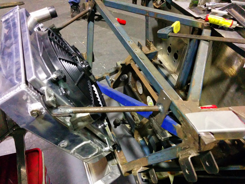
TheGecko - 26/3/13 at 02:05 PM
Some updates that hadn't made it into this build diary yet.
Built radiator mounts to suit the existing pegs on the eBay Civic radiator - generic rubber top hat bush in a short tube. Two at the bottom:
And a removable central one for the top:
End result:
There's also been some more fiddling about with panels, including pinning down the size and location of the side vents:
Some interesting work to come making a template to form nice rounded edges on those vent holes - more pics (and possibly a video) once that
happens.
I also did a quick mockup test of one panel in plain paper to resolve a question about what size sheet it needed to be cut from. Unfortunately,
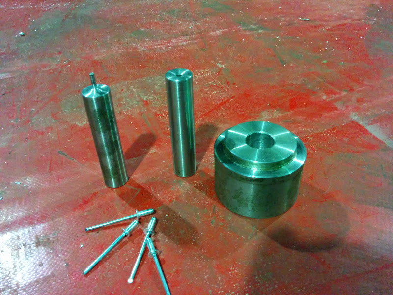
leaving a plain paper panel stuck on the car with a bored Mr H leads to unexpected "enhancements"
Last but not least, a variety of small manufactured bits have come back from plating (zinc + gold passivating + de-embrittlement) - must try to get a
better photo than this one:
Top and bottom are the rear toe links with their adjustable chassis end mounts posts on the left. They use a LH threaded 5/8" rose joint on the
inside end and the OEM Toyota tie rod end on the outside. In the middle are two front tie rod extensions and the steering intermediate shaft -
Mitsubishi Lancer column spline to Ford (Ka) UJ through to 17mm hex on modified Gemini (Chevette) rack. Hey, why make it easy on myself
Present goal is to get all the structural and panel work completed and shift the car back to my workshop for plumbing/wiring/trimming sometime in the
next 6-8 weeks. Need to extract my digit plus find some way of spending less hours in the office
TheGecko - 7/4/13 at 01:18 PM
I feel like I'm in the department of dribs-and-drabs at the moment. Lots of little invisible bits of stuff happening and very little to show.
Made up the footwell panels - drivers side needs to be set back a bit to meet the back of the pedal box.
Needs some holes - one for the column and three for the master cylinders - to be finished.
The above leaves out the column support etc all in place...
And today, finished some hidden metal work that will support the ali panel behind the rear guards. Mocked up a bit of that panel in cardboard and had
a look -the guard will need a small fillet to meet the curve of the panel.
Did the other side and added in the central lighting/grille panel then stood back for a look. Doesn't look awful
Have also made the retainers for the fuel tanks but nothing to show of them yet - soon.
Dominic
maccmike - 7/4/13 at 01:45 PM
nice sheet metal work
John Bonnett - 7/4/13 at 02:52 PM
It doesn't look awful at all Dominic, it looks really nice and very well executed. You have achieved some really tidy bends on the square tube.
Wherever you look on your project there are some very nice touches. A great thread and a great read. Thank you.
Regds
John
TheGecko - 8/4/13 at 07:26 AM
Macmike, thanks - I assume you're referencing the light/grille box? It certainly passes the "looks alright at a glance from a few metres
away" test. Up close, there's some rough edges
John, thanks also - I've spent a LOT of time sketching and fiddling with various scale models to find pleasant shapes from simple elements.
I.e. there's no double curvature panels on the car (other than the fibreglass guards) but I think it all works pretty well. Somewhere I've
got a sketch of how the various single curvature pieces intersect at the back - it's harder to draw than it is to build It's a little
influenced by Ford's "New Edge" design language, which used the intersection lines
between curves to form styling highlights.
The bends in the square tube were all made with a borrowed (cheap Chinese) bender and are in 3/4" (19mm) tube rather than 25mm to ease the
process. Hilariously, at the time I made the bends, I was still sketching the final rear end layout so the bends were just short pieces with a
(roughly) 90 degree corner and short straight tails. The "proper" way which would have been to bend them to length as continuous pieces. I
did at least get lots of practice butt welding bits of 3/4"-18g tube together
If I ever built another (Hah!) I'd know so many better ways of doing things Oh well, Per ardua ad astra and all that.
Dominic
TheGecko - 28/4/13 at 12:05 PM
Stuffing around with the footwell panel ended with me making it again. It needed a 3mm step in it because, for reasons known only to Willwood, their
clutch pedal assembly is 1/8" longer than the brake one
Anyway, here's the end result, along with the floor panel to get ones feet up to the same level as the pedals. Just need a trio of 1-3/8"
holes for the master cylinders and one for the steering intermediate shaft and it's done.
Might finally get onto something other than footwells in the next session
D
John Bonnett - 28/4/13 at 01:09 PM
Another example of the care and attention to detail Dominic. The stiffening swages have been beautifully executed. Have you got a beading machine or
did you put them in by hand? The fit and the folding is superb. Well done
John
TheGecko - 28/4/13 at 01:55 PM
John,
The swages were put on with a set of jenny rolls - one of the advantages of the car being in the workshop it currently is. I'm a little annoyed
about the beads in the floor panel - they should go down rather than up but I forgot what side of the sheet I was working on That part of the
floor will get covered with carpet or something non-slip anyway so it probably doesn't matter a whole lot. Still annoying though
With the completion of these panels I feel like the car is finally starting to come together, which is nice after all this time.......
Next workshop sessions are Wednesday & Thursday nights this week. More updates as they happen.
D
John Bonnett - 28/4/13 at 05:02 PM
quote:Originally posted by TheGecko
John,
The swages were put on with a set of jenny rolls - one of the advantages of the car being in the workshop it currently is. I'm a little annoyed
about the beads in the floor panel - they should go down rather than up but I forgot what side of the sheet I was working on That part of the
floor will get covered with carpet or something non-slip anyway so it probably doesn't matter a whole lot. Still annoying though
With the completion of these panels I feel like the car is finally starting to come together, which is nice after all this time.......
Next workshop sessions are Wednesday & Thursday nights this week. More updates as they happen.
D
Ah, but being that way up, they won't fill up with dirt TheGecko - 16/5/13 at 02:05 PM
So, no updates here for a while but still plenty going on.
Bolted on the neat little mount for the High Level Brake Light (manufacture by Mr H)....
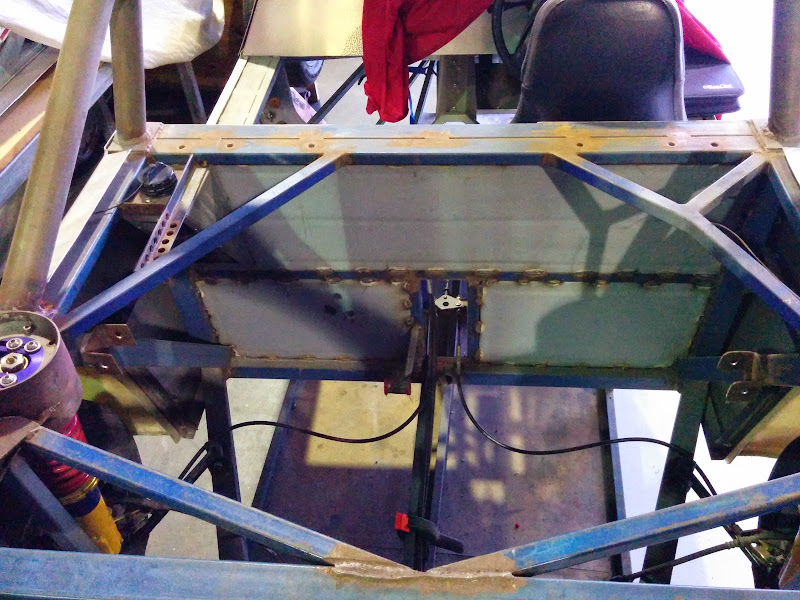
Made a tunnel to cover the water pipes etc that will run from the front to the back. Was originally folded up in one piece but I had to split and
join it with rivnuts to make it possible to get in or out of the chassis Still a little bit of trimming etc to do on mounting flanges.
Then some careful measuring was done to establish maximum load size in the front luggage area
Based on that, I made a boot floor to keep the carton off the passengers legs:
Can't do the same thing on the drivers side because the column etc is in the way. So made a little version which will serve to hold jack, tools,
etc.
There's still a flat panel to come to cover the column area - ran out of time tonight.
All in all, pretty happy with the last week's progress. Still aiming to get all of the panel-type work done over the next 6-8 weeks and get the
car back into my workshop for wiring, plumbing, and trimming.
More soon.
D
TheGecko - 24/5/13 at 01:18 AM
Made the cover panel for the column area - still needs rivnuts etc.
Also realised I hadn't posted these pics. Rear calipers are finalised after I sourced a pair of late-Mk2 MR2 (SW20) rear calipers. These fit
over the Corolla 22mm discs, have a handbrake mechanism, and (best of all) bolt straight up to the Corolla upright. No adapters etc required
Although nowhere near as light as the XF Falcon calipers I was looking at using, the ease of mounting sold me on these.
Back to bodywork.... There was an appropriately sized scrap of 1.2mm ali lying there on Wednesday night so I dragged out the partially complete
nosecone buck and had a little play....
Trim the sheet (roughly, this is just a trial) and wrap it around the buck with a couple of wood screws into the back to hold it still....
Smash away at the leading edge with the rawhide hammer for a bit and discover pretty quickly that I'd left waaaay too much edge to knock over,
particularly in the corners End result was that I had to snip roughly into the corners to untangle the mess and at least let the rest wrap
over. So, some lessons learned about sizing etc, which was the point of the exercise after all. If you ignore the chewed up corners, the rest
doesn't actually look too bad for what was probably 30 minutes work
Looks both better and worse in the photo than in real life
This weekend will be back on the welder for little bits of bracketry like bottom harness mounts, handbrake lever, fuel filler, and plenty of others I
can't recall right now.
It's progress I suppose.....
D
TheGecko - 1/7/13 at 02:51 PM
Despite the lack of updates I've been slowly getting things done.
Cut-and-shut the Lancer donor filler neck:
Just found I don't have a decent photo of the engine bay side of that but there's a full metal cover over the pipe so it's not
"in" the engine bay.
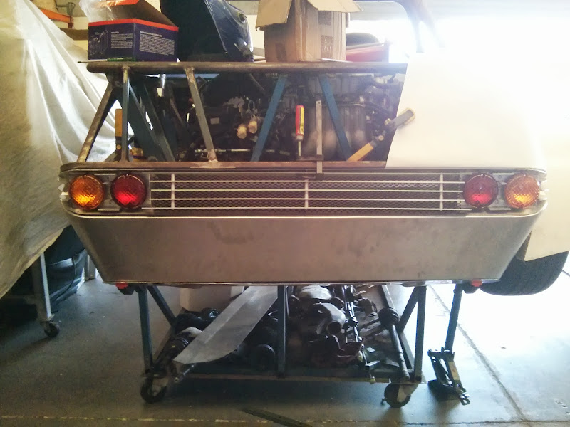
Have spent an inordinate amount of time faffing around with the grille that will fill the space between the rear lights. First I cut and spaced five
ali-strips (temporary bolts obviously):
Then, with some posts to mount the lights on, I could trim some ali angle down like so:
and end up with this result:
All of this will, of course, be painted black when it's finished. Need to make some more bits for the outer corners plus the proper top and
bottom mounting tabs for the main grille piece, and it's done.
Have also mounted a handbrake lever and measured up but not yet mounted the gear lever. Just waiting now for the custom cables for both of those
(which should be by the end of the week) and there'll be some fitting up and bracket making to do.
D
TheGecko - 2/9/13 at 10:09 AM
Been too busy with work, home, and organising committee for the Nationals (in pretty much that order) to do
much work that actually shows. However, here's a few updates.
Gear shift mechanism has been chopped, flipped, swapped, fiddled, and generally buggerised-around-with until it moves the cables in the right
direction for a given stick movement. Temp mount need to be replaced with something more permanent and the relationship between the gear shift cables
and the handbrake, with its own set of cables and compensator, needs some addressing
My recommendation for aspiring middy builders - start your design with the gearshift and handbrake and then work outwards from there
Said handbrake compensator, manufactured from raw materials by mine own fair hands
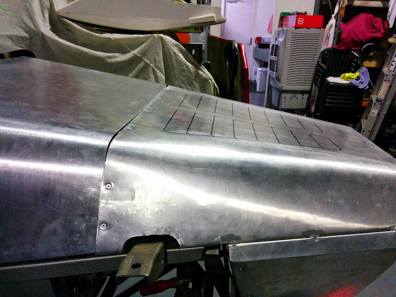
Have also been doing a bit of tin bashing, resulting in the following:
Two updates rolled into one here..... a few days later
Trimmed up the panel a bit more so the gap is virtually nil and clamped up a rear guard for a look:
Offered up the lower rear panel too - still needs to be trimmed and have its edges knocked over for riveting. Looks good already though
Next step is opening up various vent holes and flangeing over the edges - will become more clear once it's done.....
D
[Edited on 2/9/2013 by TheGecko]
TheGecko - 8/9/13 at 09:55 AM
Another successful few afternoons and evenings in the workshop.
Got the lower rear panel trimmed and knocked over onto its frame
And stuck the under tray portion on to see how it looks
Wrapped a paper template around the side and upper-rear corner (checked the guard and light bar while I was there)
And with the centre part of the grille bars (and backing mesh) loosely in
Drop the template onto the remains of a sheet of 1.2
Yay for air-shears
And spot through the existing rivet holes to locate the sheet in prep ready for rolling the corner, trimming, etc
Ran out of time to roll the corner today - probably Tuesday night's job.
D
coozer - 8/9/13 at 10:11 AM
Smashing work there, some good tips for other builders to follow.
Keep it up
TheGecko - 9/9/13 at 03:21 AM
Thanks for the support coozer. It makes the sore hands and back feel a bit more worthwhile
D
TheGecko - 10/9/13 at 01:35 PM
Another fairly successful night bashing tin
Put a 90 degree roll in the panel
Then clamped it in place and marked edges for trimming etc
Did the bottom edge first
No detail photos of the top edge going over (because some of it's not all that pretty yet ) but here's the end result with the lower
tail and grille panel in place
Now I need to make another one for the other side and then the little removable "boot lid" panel that goes between them.....
D
TheGecko - 14/9/13 at 09:27 AM
Not getting much opportunity to work on the car - trade-off with it being in Paul's workshop is that it's a 50km round trip
Still, got the top edges of the side/rear panel tidied up enough to be presentable
Plus, I've been doing some wood-work.....
Which, with a test scrap of ali in it, looks like this...
And makes parts like this..
Some adjustments needed to various dimensions before it's ready for prime time (i.e. to use on an existing panel )
Nothing more until some time next week now.....
John Bonnett - 14/9/13 at 10:11 AM
quote:Originally posted by TheGecko
Not getting much opportunity to work on the car - trade-off with it being in Paul's workshop is that it's a 50km round trip
Still, got the top edges of the side/rear panel tidied up enough to be presentable
Plus, I've been doing some wood-work.....
Which, with a test scrap of ali in it, looks like this...
And makes parts like this..
Some adjustments needed to various dimensions before it's ready for prime time (i.e. to use on an existing panel )
Nothing more until some time next week now.....
Ah, you've discovered the joys of hammerforming Dominic. You're on the slippery slope now. I did warn you that metal shaping can take over
your life
The whole project is absolutely magnificent and I really enjoy reading about it and of course looking at the pictures.
I'd appreciate your advice on how best to load pictures up and i'll then update my project.
Best regards
John
TheGecko - 14/9/13 at 10:19 AM
Thanks John. In some ways I wish I was at the beginning of the project again because there's so much I've learned along the way that
I'd like to apply
I'll write you a direct email about how I post images here - hopefully it'll work for you.
D
John Bonnett - 14/9/13 at 12:38 PM
quote:Originally posted by TheGecko
Thanks John. In some ways I wish I was at the beginning of the project again because there's so much I've learned along the way that
I'd like to apply
I'll write you a direct email about how I post images here - hopefully it'll work for you.
D
That would be really good Dominic, thank you. I think we have all been in that position where you have learned from your experience and realise that
there are sometimes other and possibly better ways to tackle a job or even maybe an improvement in the design. But you have every reason to be really
proud of what you have achieved. It is a terrific undertaking to build a car from scratch and the first drive will be absolutely memorable.
You'll think, "I made this, and I'm driving it" And then you'll smile TheGecko - 10/11/13 at 12:28 PM
There's a few updates I hadn't got around to posting here due to being busy with the Nationals and then sick so, here they are.....
I found time to cut and fit the seat back panels:
Got a little more done than I thought I might before the car got "craned" out and onto a trailer for the trip up to the Nationals - one rear
guard is properly attached at least and the rear grille section is now properly mounted too. Best of all, the car sat on the ground on four wheels for
the first time ever Bad photo, but you get the idea....
Crane lift shows where the CofG currently is - directly under the roll bar (Coops is just steadying the front to stop some sway - it's level on
its own)
Been away plenty since the Nationals (and getting over the flu I caught too) but finally getting a little bit more done on the car over the last week
or so.
Got the other rear guard mounted (would have been nice to have this on for the Nats - oh well):
One of the problems that became apparent (once all of the suspension was put together and the car put on the ground) was that the top shock mounts
were in the wrong place. For reasons I can't explain, I centred them over the middle of the bottom wishbone, which means the springs touched the
top wishbone due the the caster angle. The proper way to fix it was to cut the mounts off, make new ones and mount them 20mm further back. Some
things I learnt today:
Plasma cutters are great!
In experienced hands, a plasma cutter makes very short work of cutting out complicated brackets
In less experienced hands, plasma cutter burns are pretty much self cauterising
Here's the first bracket after some clean up and welding plus the second one after the cutting out phase:
With the two brackets finished (and a coat of primer) they were clamped up with some straight bars to ensure correct alignment and then tacked up to
check fit:
End result? The springs now fit
Ran out of time for anything else today - more as it happens.
D
TheGecko - 5/12/13 at 06:41 AM
Been silly busy in the run towards the end of the year so haven't got much done on the car. Completed a number of little jobs, the most visible
of which is the rear undertray, which is now properly trimmed and has all of its mounting bolts done.
The diffuser vanes are mostly for what I, in colloquial Australian language, would call "Wank Factor"
Next two big-ticket items to finish are the nosecone and bonnet. After that (or before, depending on how the mood takes me), the engine cover. That
will then mark pretty much the end of the sheet metalwork phase of the project and I can get onto the simple stuff like plumbing and wiring
D
TheGecko - 8/12/13 at 10:07 AM
Got a little more done today. Most notably, I finally made the middle fill-in panel for the back of the car.
Makes quite a difference to the appearance to have that gap finally closed The sharp-eyed will notice some imperfections around the corners. A
little judicious TIG work will happen someday soon to correct those.
I also fiddled around with headlight mountings (but forgot to take any photos of that) and measured, thought, re-measured, re-thought, then measured
and thought some more, about scuttle/bonnet/nosecone juxtaposition & relationship. they may yet all become one big forward-tilting piece......
More as it happens.
D
[Edited on 8/12/2013 by TheGecko]
TheGecko - 17/12/13 at 12:45 PM
Behind the lower-rear panel will be the muffler and cat so some extra ventilation has been deemed appropriate. Did a bit of doodling of possible
vents first:
Then took the bit between my teeth and cut big holes in a perfectly innocent panel
Used some home made "flanging sticks" to put some edge on the holes and stiffen things up:
And stuck it all back on the car for a look see. Given that the dimensions were chosen by a fairly arbitrary process, the end result looks OK I
think. In finished form, the holes will get filled with black mesh - just haven't got to that bit yet.
Plenty more holes like this to come........
Dominic
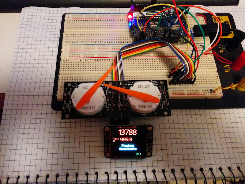
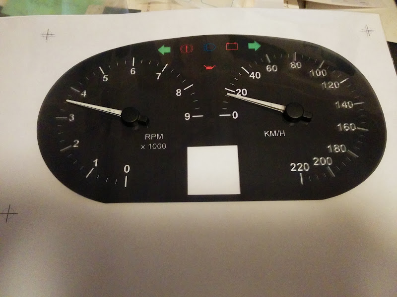
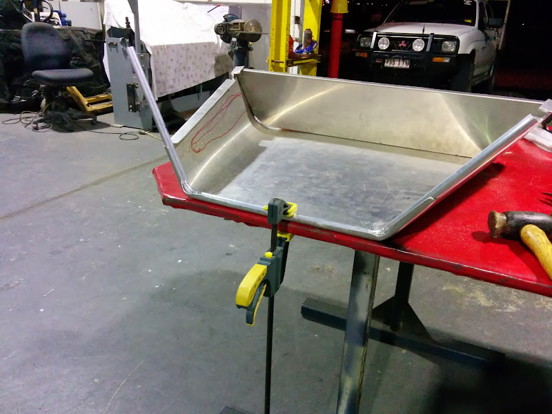
TheGecko - 28/12/13 at 11:42 AM
XMas etc is limiting my build activity at present. However, here's a teaser for something else I've been working on. Any guesses?
Dominic
ashg - 28/12/13 at 01:53 PM
that looks very pretty, allways fancied doing a diy dash do share
TheGecko - 28/12/13 at 02:02 PM
It's very much just the beginning of something right now - I'll be posting more about it as it proceeds. Major components right now are:
Switec X27 gauge steppers on TheRengineer.com breakout boards
Freetronics.com 128x128 OLED display (nice and bright)
Freetronics Eleven Arduino Uno clone
The Arduino Uno is going to be swapped for a 2560 Mega soon as there's just not enough I/O (particularly interrupts) on the Uno.
Working on it is certainly reminding me that I prefer byte bending to metal work
Dominic
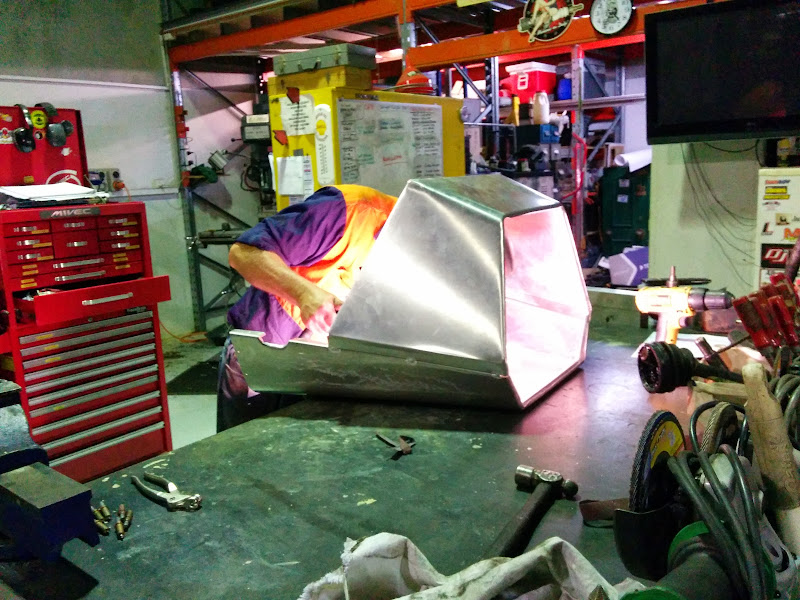
TheGecko - 1/1/14 at 03:17 AM
I said the nosecone/bonnet/scuttle was "coming soon" - made a start yesterday
Quite a while back, I made this wooden buck (which is in a top and bottom half):
Which has been fitted with nice hardwood leading edges:
Yesterday I "Xmas-wrapped" the top half to make a pattern:
Which got me this far today:
Thursday is "smack hell out of innocent aluminium with a body hammer" day, whence I will try to form the leading edge. Then the lower half
gets made via the same method and the two halves will get TIG'ed together.
Dominic
[Edited on 1/1/2014 by TheGecko]
TheGecko - 4/1/14 at 09:21 AM
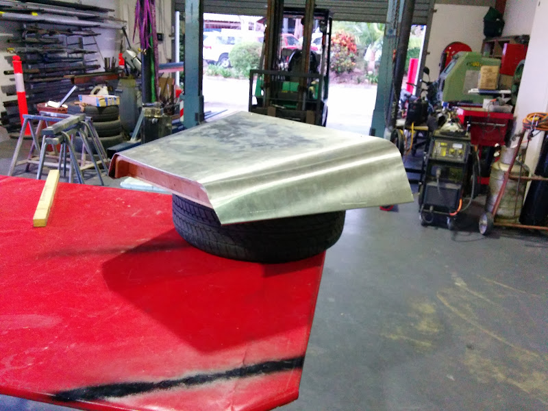
Having smacked the front edge into some semblance of a consistent curve I arrive at this:
After some trimming to make clearance reliefs and more hammer/dolly work around their edges, it looks like this:
Too hot in the workshop today so didn't get much more done. Need to do some more fiddling with the bottom half of the forming buck so it's
ready for the next stage.
{Next Day}
Waaaay too hot to be doing much today, plus I need to do more work than expected to get the bottom half of the nosecone buck sorted. So, all I got
done was this:
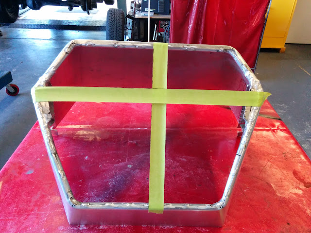
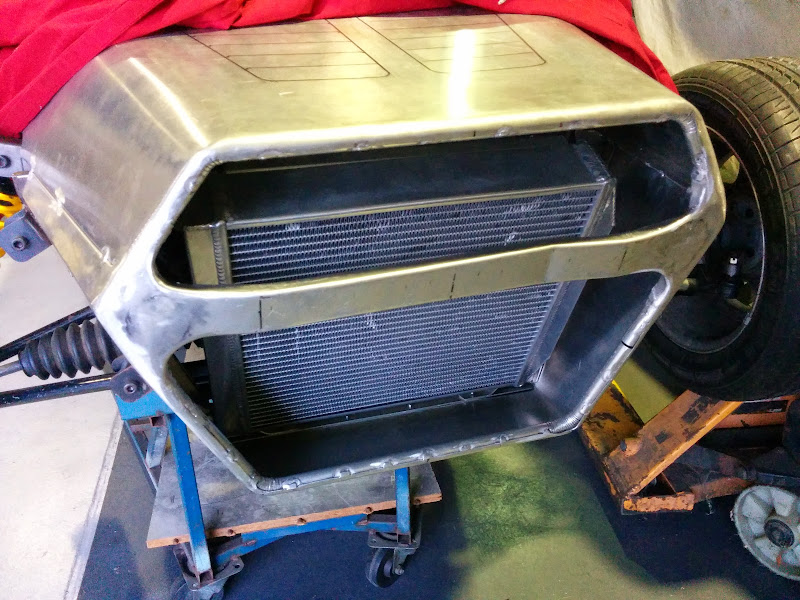
The diaphragm panel stiffens the nosecone and stops the radiator venting into the "luggage" space.
The radiator will need to vent somewhere so....
Before any points it out, yes I'm aware that that isn't a big enough exit vent - it's just a "what would that look like"
sketch at present.
No more workshop till next week now.
Dominic
TheGecko - 9/1/14 at 01:30 PM
Another two days worth of work rolled into one update:
Marked out the pattern for the bottom half of the nosecone using the wooden buck:
Cut the resulting "bowtie" shape out of 1.2mm ali and started rolling the corners:
The corner radii are too small for the forming rolls so I had to use classic methods - pipe, clamp, and brute force
Only got as far as folding the rear flanges tonight - next visit, I'll finish the top flanges (where it'll join to the top half of the nose)
and roll the front edge over:
(Second night):
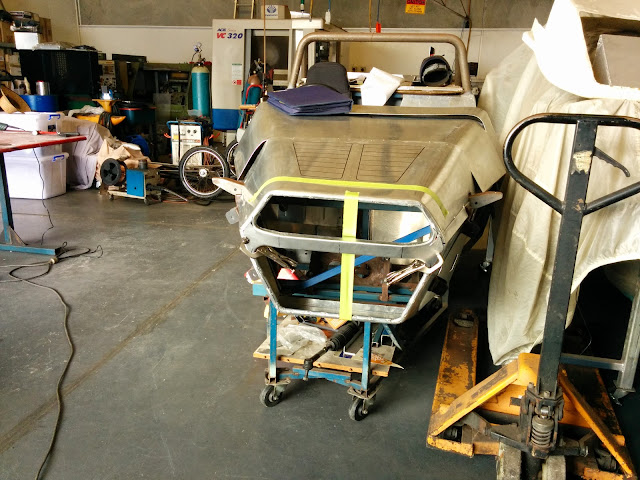
Offered the part up to the chassis and trimmed somewhat where the radiator support interfered with the bottom edge/face:
Trimmed things at the top a bit so I could drop the top half of the nosecone in place (with the edges just overlapping for now):
Yes, it is a bit "wide mouthed frog" There's going to need to be some attention to that aspect of it - it will look somewhat smaller
once the edges are rolled in and a it's in body colour with a black grille etc.
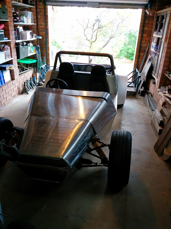
Took an overall shot as well to get a sense of how it's all coming together:
I'm pretty pleased with how it's looking but maybe it's a face only a mother could love
Now, as confession is good for the soul, I must admit that I am going to have to remake the whole bottom half of the nose. In the process of folding
edges, trimming notches, etc, etc, I basically f***ed it up . So, it's now getting treated as a pattern to make a second one without all
the various issues that caused me to ruin this one. But I won't get back to the car until next week now....
More when it happens,
Dominic
Fred W B - 9/1/14 at 05:58 PM
Looking good, and don't stress, the second part you make is always much better then the first..
Regards
Fred W B
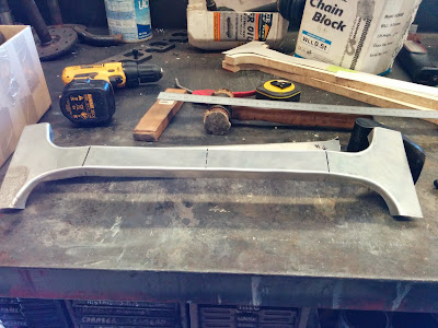
TheGecko - 27/1/14 at 01:16 PM
Thanks Fred - I'm well familiar with the "second attempt" effect
Haven't got back to the bottom half of the nosecone yet, but I have rolled both a scuttle and a bonnet, although there's some more trimming
and finishing needed for both of them yet.
Plus, I've continued on with my dash development, and have got this far with the panel overlay. It looks better in the flesh, because it's
reverse printed on transparency film and isn't being held properly flat in this picture.
Dominic
TheGecko - 10/2/14 at 09:49 AM
Not much to show for the last few weeks of work. This bit actually photographed OK so I'll put it up. And don't worry, a hole got cut for
the tie rod too, I just didn't take another photo
Dominic
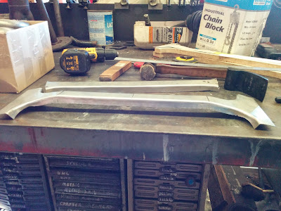
TheGecko - 9/3/14 at 08:22 AM
Some updates for the last 4 weeks of effort:
Marked the bonnet to size and formed the bottom edges (this picture was before I'd done the left side which is why it's sagging):
Remade the bottom half of the nosecone and got it (temporarily) joined to the top half for fitting. Still needs its front edge rolled over but I need
to modify my forming buck a little for it to fit.
Dominic
[Edited on 9/3/2014 by TheGecko]
TheGecko - 11/3/14 at 01:28 PM
Got a bit done tonight. Having trimmed the wooden buck down enough (just) I squeezed the bottom half of the nosecone over it, marked, removed,
trimmed, re-fitted, and then hammered the edge over. Having done that, I could turn to my "What's an easy way of reinforcing this edge and
making sure it's got a nice profile" solution a.k.a. a length of 16mm ali tube Some pie-cuts in the corners (which will get a visit from
Mr TIG) and Robert's your mother's brother.
Need to get another bit of tube because I only grabbed enough to try the idea and was a little surprised how well it went so only got this far
tonight:
Don't worry - there's a mitigation process in the planning as well to address the Whale Shark (�, �, and TM) look of the front
More on Thursday night (probably).
D
[Edited on 11/3/2014 by TheGecko]
TheGecko - 13/3/14 at 12:43 PM
The anti-Whale Shark work has begun This is just mocked up in card here although I have started on the ali piece. Stuck a wheel on to get some
sense of proportion too.
Profile looks alright to me as well....
Sunday is finish the nosecone day:
Finish the cross piece/splitter
TIG all of the corners of the edging tubes
TIG any other dodgy corners etc
Make an internal C-section stiffener for the back edge where it'll hinge from
Dimple and countersink rivet lots of pieces in place
Not all of the above will necessarily get done. If it does, then I can:
Cut out the front diagonal and put it in the other way so the bottom radiator hose can get through
Remake the bottom radiator mounts for the new position
ditto the top radiator mounts/s
Trim the "sticky out" ears at the front corners of the chassis (after reinforcing the inner corner)
Make the baffle panel to shroud the radiator to the nosecone
So, not much to do then
More as it happens.
TheGecko - 23/3/14 at 09:19 AM
Bit of a lag in updates due to illness/work/general lassitude
Today I made a hammer form and knocked out a proper cross rail for the nosecone:
After some trimming, that was rough fitted:
TIG welder is out of action at present so nothing's welded yet. I did have another stab at what the radiator exit grille might look like, in
preparation for getting a prototype waterjet cut in a week or so (I'm piggy backing on one of Paul's orders to avoid the minimum charge):
As well, there's a variety of places where I'll need to butt join panels so it's nice to have a way to keep things clamped and aligned.
You can buy these clamps but I'm not paying $12/ea + postage for something that can be made from scrap in half an hour or so. Made four to
start with but may yet make a few more:
Hopefully the TIG will be back online on Tuesday night and the nosecone can start to come together.
More then,
Dominic
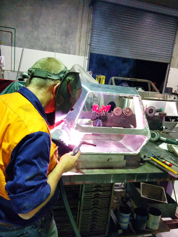
TheGecko - 6/4/14 at 10:21 AM
Well, sh*t
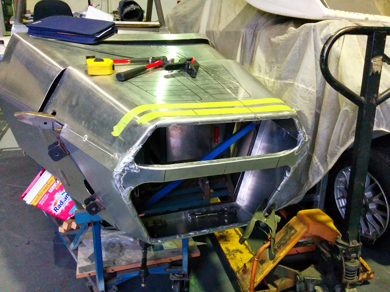
Since last we spoke, quite of bit of this has happened:
and some of this as well:
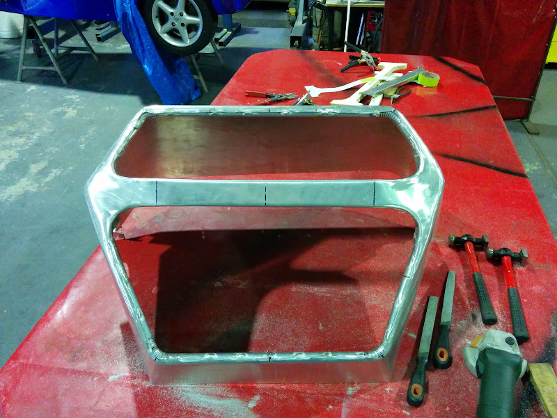
The end result being this:
However, your eyes do not deceive - those top corners are NOT the same shape This is the result of me not checking carefully while the nose was
being rolled around on the bench for tacking and then welding. So, on Thursday night I spent some quality time with sash cramps etc trying to pull
the whole thing back into shape. And then I cut partially into the joints around the cross-piece and leaned on it some more. And then I cut one
whole end of the cross piece free (with a sproooooingg of released tension!) and tried some more. And finally, I hacked the whole cross piece out and
forced the cone back into its proper shape
So, now I have to make a new cross piece (not so bad, I have the former etc), clean out the remains of the old one (crappy, fiddly, work with a flap
wheel), trim the new one to fit (I know how to do that now!), and ask (i.e. pay) Paul to weld it all up - AGAIN!
Measure 400 times, weld once. There endeth the lesson........
[Edited on 6/4/2014 by TheGecko]
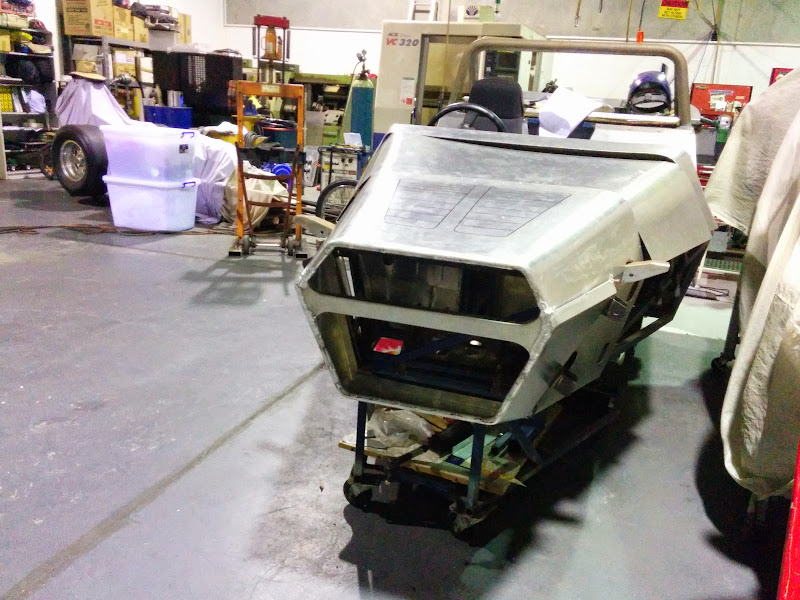
TheGecko - 6/4/14 at 11:17 AM
The previous update was actually from 2 days ago, I just hadn't posted it here yet.
OK, after Thursday night's frustrating setback today was pretty successful
Made a new cross bar and shrunk the flanges a little at each side to put some more shape in it:
Much careful laying out of centre lines etc (don't panic, the centre is the left edge of that vertical tape strip!) and checking measurements
etc...
Trim the new part and offer it up...
Tack it in place using the chassis as the ultimate alignment jig
More checking measurements and alignments and then weld it all in
Then lift off and dress all of the welds. And don't worry, it's still square - the angle of the photo just makes it look skew
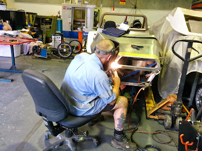
Greatly satisfying to get to this point. Many, many thanks to Paul for cheerfully (well, as cheerful as Paul ever is ) welding it all together
for me twice in a week!
Next is finish bonnet and latches and we're getting much closer to body work done. Aim is to get it out of Paul's workshop and back to mine
before ANZAC day.
D
kb58 - 8/4/14 at 01:03 AM
Hello sunburn... or worse. I admit that I've done that myself, with the excuse that when I do, it's because it's 100+ deg F in the
garage.
TheGecko - 8/4/14 at 04:41 AM
quote:Originally posted by kb58
Hello sunburn... or worse. I admit that I've done that myself, with the excuse that when I do, it's because it's 100+ deg F in the
garage.
Strangely enough, Paul (that's who's welding in those pics, not me) rarely seem to cover up much for TIG work although he
certainly does for extended MIG sessions. From the colour of the TIG arc I would have assumed it's just as bad for UV content?
He's been welding for 40-odd years so he seems to know what he's doing I know I've given myself some fabulous sunburns with the
MIG
D
TheGecko - 15/4/14 at 02:03 PM
Not much progress since last update for various reasons. After the welding of the new crosspiece, there was a hollow on each side, as per picture:
Some judicious hammer and dolly work saw that reduced to basically nil:
The only other thing worth showing a picture off is the mockup set of grille bars I made to check proportions etc with. They don't photograph
well, being (very) matte black but you get the idea:
The final shape will be a somewhat flatter for that top bar so it follows the shape of the nose better.
TheGecko - 29/4/14 at 11:30 AM
Been busy doing anything but working on the car over Easter etc - starting to get a bit done again now.
Hinged the nosecone off the bottom front of the chassis:
Which of course then makes it clear that I hadn't thought through the pivot radius etc viz-a-viz the notches that clear the headlight mounts
Some judicious trimming has made the notches bigger and I can pretend it was designed that way This shot shows the trimmed notches and the reason
for tilting the nosecone....
Yep, the whole lot will tilt as an assembly.
The reason I needed to finalise the bonnet/nosecone was because I'm trying to finish the new radiator mounts. It's mocked up in position
but that's as far as I got tonight:
There's always interesting distractions in Paul's workshop.......
520ci Keith Black alloy-block dragster motor - in need of some love after the sudden departure of a con rod . Obviously not the first time as
evidenced by the various repairs visible on the outside
More (on my car at least) as it happens.
TheGecko - 31/5/14 at 03:22 AM
Throwing a whole bunch of updates in at once here as I haven't been organised in posting.
Busy doing house projects at present (if I never see another fence paling I'll be a happy man!) so the car isn't getting much of my time.
Since the last update, Paul has made a nice little dimple tool for me to set the ali sheets for countersunk rivets. I drill 1/8"; setup the tool
through the hole on the guide pin; wack with BFH; drill to 5/32" (final rivet size) to clean up the resultant distortion of the hole; and then
rivet. There's some tweaking yet to get my technique right but here's the tool and a few examples...
The apparent distortion around the riveted area isn't as bad as it looks in the photo A quick skim of filler and block down before paint
These rivets are just holding the stiffener diaphragm panel inside the nosecone - connecting the bonnet is to come.
In other news, the (new) radiator mounts have been finalised. Didn't take a pic of the bottom mounts but the tops are a pair of light tension
struts with a rubber grommet at the radiator end. Couple of M5 or M6 rivnuts in the chassis at each side and they're done. They'll also
get cleaned up and go off the the platers in whatever next batch of plating Paul sends out.
----------------------------------------------------------
-- Next Update
----------------------------------------------------------
Hasn't been much in the way of updates recently - lots of non-clubbie things going on, consuming both time and mental energy
Been pushing on trying to get the car out of Paul's workshop and back to my place and went at it today trying to finish that process. What is it
that they say? "More haste, less speed". Don't rush is what it comes down to. For instance, if you rush, you might leave a hinged
aluminium nosecone carelessly propped and then move something else causing the whole assembly to swing down and around until the build table
interrupts progress......
Oh goody, a reason to practice my panel beating
On the (slightly) plus side, I did pull the engine. It's going to stay at Paul's for now so that the various belt tensioner etc mods can be
done. Interesting to see the engine bay empty again:
Current plan is to get the car back here on Saturday morning. Let's see what else I can f*ck up in the interim.......
----------------------------------------------------------
-- Next Update
----------------------------------------------------------
Well, after more than 2 years in Paul's workshop, the Gecko is back in its' birth place to be completed Will be nice to be able to walk
downstairs and do 30 minutes or an hour on the car without having a 50km and 1 hour round trip to do it.
There's still HUUUGE amounts of work to be done but Paul's input over the last 2 years has brought it to a point where I feel confident in
finishing it sooner rather than later.
D
[Edited on 31/5/2014 by TheGecko]
beebo82 - 24/6/14 at 09:39 PM
Really enjoyed reading this whole thread, can't wait for the next update!
TheGecko - 25/6/14 at 01:43 AM
quote:Originally posted by beebo82
Really enjoyed reading this whole thread, can't wait for the next update!
Thanks beebo - I was starting to wonder if anyone was actually reading my updates
Now that the car's back in my own workshop, I've hardly touched it Should be some updates in the next fortnight or so - the engine cover
is the main remaining piece of panel work so it's next.
D
rick q - 25/6/14 at 04:09 AM
quote:
I was starting to wonder if anyone was actually reading my updates
Hmm - I've been watching .......... and quietly judging
.
.
.
.
.
.
Looking great Dom - I'm sure there's plenty of us waiting for the next installment
WanchaiWarrior - 25/6/14 at 09:22 AM
I also am interested in your updates. Always a good read. And being quite close as well.
TheGecko - 2/9/14 at 12:02 PM
Wow, 3 months without posting an update I must have got heaps done, right? Errrrr, not so much Lots of reasons, some good (to me at
least), some not so good...
Anyway, here's a small update. While I've had the car back in my workshop, the motor/gearbox was still at Paul's workshop while he did
some simplifying of the serpentine belt arrangement for me. Here's the before from when I first bought the motor, with PS pump at the back, and
alternator plus air-con compressor down low at the front.
After, things are a little simpler
Alternator at back and nothing else belt driven. The water pump is gutted enough that leaving it in place without any drive isn't an issue -
I've got a Davies-Craig EWP to replace it.
Not much else visible to show just yet although there's been some furious measuring and sketching going on around the engine bay More
soon.......
Dominic
beebo82 - 3/9/14 at 04:06 PM
Good news! Thought we'd lost you! Keep the updates coming.
TheGecko - 16/2/16 at 12:07 PM
I'm not dead!
Yes, it's been a little while since the last update - I'll bung a bunch of things in together here with some indicative dates....
21 Jan 2015:
These arrived today:
Not that the SVC lights I have/had are bad but these are nicer
Also did some (a very little) workshop cleanup that day and remembered this quote from a Hot Rod forum, talking about messy vs clean workshops:
quote:I've seen some places that are like an operating room, others are so fucked up that if a tornado went thru there, the tornado would
actually put some shyt away.
I'm still waiting for a helpful tornado
March 2015:
Started digging into the engine loom - this is maybe a bit under half of it
November 2015:
Among the many (many!) things that stop me making much progress on the car is the fact that the workshop is a shyt storm of heroic proportions
Can't work on a car if you can barely get to it. So, today started the great cleanup. Stage 1 was stick a new timber rack up on the wall and
setup dedicated sheet material storage under that. Recovered a startling amount of floor space already!
February 2016:
Little bits are still going on even if it's hard to measure how slowly First stab at some grille bars in ali - definitely NOT the final
version, which will be:
more evenly matched to the opening width for all bars
more evenly adjusted front to back to better align with the cross bar
cut away somewhat at the back to make them lighter
painted satin black (because a good coat of black hides so much evil)
These are just "hanging" in the opening too so they're more than a bit askew....
Much more significant update coming next....
P.S. There's some "creative" spelling of one word that appears twice in this post. The forum censors it otherwise (which makes me
sound like a 6 year old) but, amusingly, not the "other" word
[Edited on 16/2/2016 by TheGecko]
beebo82 - 16/2/16 at 12:11 PM
Glad you're back! Keep the updates coming.
TheGecko - 16/2/16 at 12:30 PM
Long, long ago, when I started this project, I bought a "Silvertop" 20-valve Corolla drive train (this is a JDM only motor but common in
Australia as an import for modifiers). All of the initial construction was done around that, including using Corolla uprights and (modified) struts in
the rear suspension. For that matter, the whole layout of the rear end assumes Corolla track dimensions.
However, building an ICV (Individually Constructed Vehicle) in Australia is not a simple task. One of the big bugbears is emissions compliance, and
the 20-valve is NOT compliant to the ADR's (Australian Design Rules). It can be made compliant (to ADR37/01) but that requires some
serious money i.e. nearly as much as I paid for the motor/box originally . Then, for extra amusement, the local registration authorities started
making noises about requiring ADR79 compliance for ICVs (this was in 2007). So, I took what looked like a reasonable step and bought a much newer,
Australian delivered motor, from a 2006 Lancer.
That introduces a collection of issues of its own The track and CVs are both different to the Corolla, necessitating custom axles - achievable by
spending enough money. The much bigger issue is the deeply integrated electronics. ABS, anti-theft, cruise control, instruments, all intimately
interlinked by CANBUS network. Dealing with this has been a problem to say the least. Given that the authorities then fell back to ADR37/01 compliance
after all just makes it all the more unpleasant.
Now I could "just" use an alternative ECU. That, however, would still need to be bought, wired, tuned and, at the end of the day, hidden
from the approving engineer (who will be expecting a factory ECU to prove compliance).
A little lateral thinking, plus recent discussion on the OzClubbies forum about 7A-FE motors threw up another possibility. The 7A-FE is a 1.8 litre
DOHC (with the narrow angle "economy" twincam head design) that was offered in various Australian delivered Corolla's from the early
'90s all the way into 2001 when they switched to the ZZ motor family. ADR37/01 compliance starts from new models in '97 and all models from
'99.
I set up a ""saved search" on Gumtree which emailed my its finds each morning. And on Saturday, I drove home this for a few hundred
dollars:
That's a 1999 Corolla with 7A-FE (as per the nice compliance plate)
This is a 37/01 compliant motor, gearbox, all electronics, ready to drop into the existing suspension without custom axles. No anti-theft, no CANBUS
Biggest part of it will be making new engine mounts, which is relatively straightforward.
Plus, my helpful friends on the OzClubbies forum are all champing at the bit to come for a working bee and pull the motor ASAP.
Hopefully I'm now moving forward again
More updates soon I expect.
Dominic
[Edited on 16/2/2016 by TheGecko]
TheGecko - 17/3/16 at 12:52 PM
So, the day for "Gutting the Corolla" was Saturday and here's a few pictures of what went on, courtesy of my wife and her camera.
Special mention to for allowing me to pull a car apart in our driveway, with a gang of mates, on our wedding anniversary
Probably more clubbies than our sleepy cul-de-sac is used to (there were two more but Leanne only grabbed this shot)
Mechanical geniuses discuss options:
You can never have too many people standing and watching
Well don't all just stand there! Drink something!
The slightly reluctant captive is released from it's boring prison
More updates soon.
D
TheGecko - 13/11/16 at 01:16 PM
After a long period of inactivity (2016 has been a royal arsehole of a year!) I'm finally back doing things
For quite a while, I've been toying with options for front indicators. The motorcycle style stalks that many use aren't ADR compliant of
course. I toyed with making my own stalks but then, after looking at what approved indicators are available, I found some nice strip style ones.
Thinking a bit more about how to mount them got me to here.
From left to right that's a clamp block, a hammerform, a pattern, an ali blank, and a final part.
After annealing and some bashing around the form, we get to this stage:
A quick trim on the bandsaw to get the angle right and here it is taped to the nose for a look.
As always, when you need two of something, you end up making three because the first one shows you all of the mistakes
The next two will go pretty quickly (I hope).
Progress is progress.....
[
[Edited on 13/11/2016 by TheGecko]
TheGecko - 14/8/17 at 04:52 AM
I posted this elsewhere the other day and supposed I should repeat it here to reassure everyone I'm still alive:
After not doing much meaningful work on the car for ages, I sold some surplus parts a week or so back. In the process, I had to clean up the workshop
enough to get the parts out . Decided to stick the wheels and loose panels back on to remind me what I'm trying to do.
The same day also marked one year since my Dad died - I think I owe it to him to finish the project he always asked about. #findingmotivation
Angel Acevedo - 14/8/17 at 06:51 PM
quote:Originally posted by TheGecko
I'm not dead!
Yes, it's been a little while since the last update - I'll bung a bunch of things in together here with some indicative dates....
21 Jan 2015:
These arrived today:
Not that the SVC lights I have/had are bad but these are nicer
...
[Edited on 16/2/2016 by TheGecko]
Taking advantage that you are alive and kicking.
Would you tell where you got these? and how much...?
I promise won�t tell SWMBO...
Thanks in advance
TheGecko - 14/8/17 at 08:58 PM
Angel,
Someone asked the same question on the Australian forum I'm on so I can cut-and-paste my reply from there
They're Perei ZZ-series lights, sold in Australia by Whitevision (http://whitevision.com.au/products/). They're mix-and-match components
with the 95mm stop-tail ring and the 55mm indicator or reverse. There's also a larger 122mm outer ring in the Perei range but I don't think
Whitevision carry them. Too big for clubbies anyway I'd think. They're not screamingly cheap but are sealed LED units so should be good
for the life of the car - stop/tail about $31 ea; indicators about $29; reverse (for some reason) $51 each!
I'm sure there are distributors of Perei products in your part of the world.
D
mcerd1 - 14/8/17 at 09:18 PM
^^
they look more or less the same as these ones too:
 )
) 
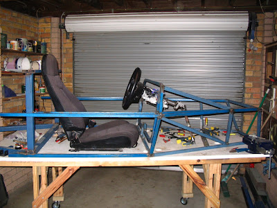


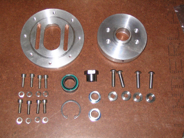

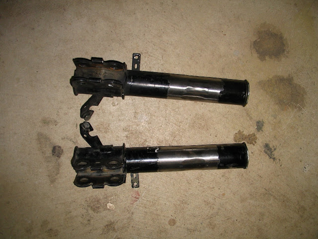
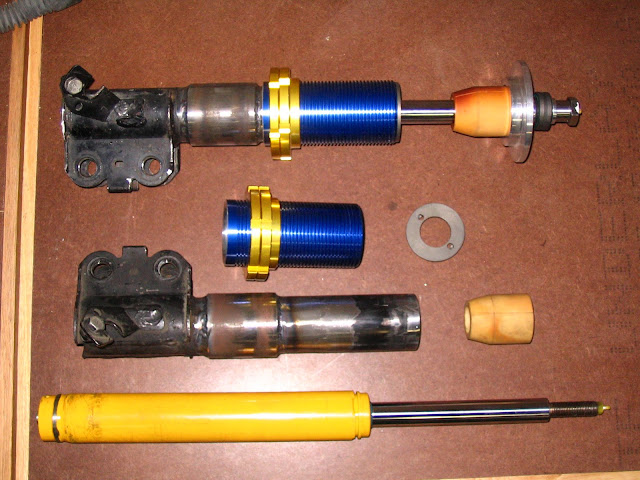

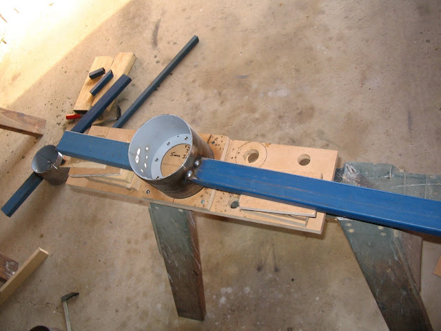


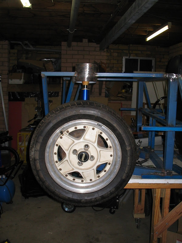
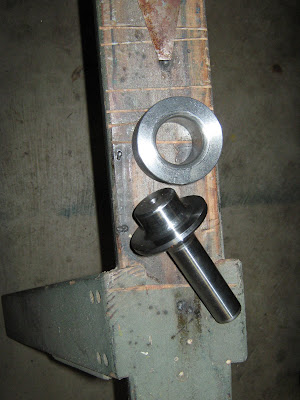
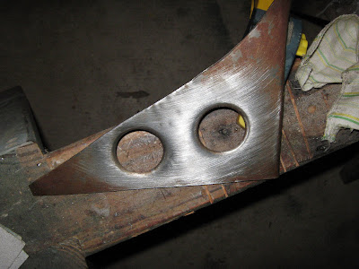

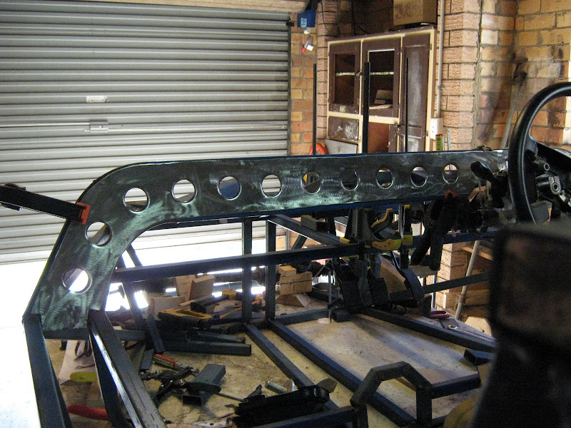
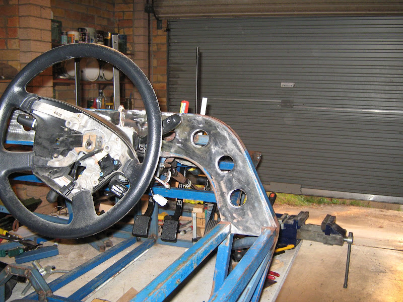
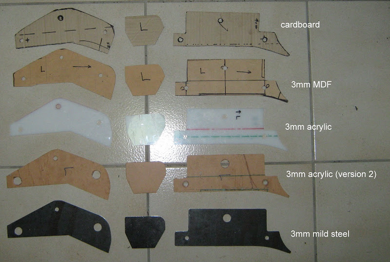
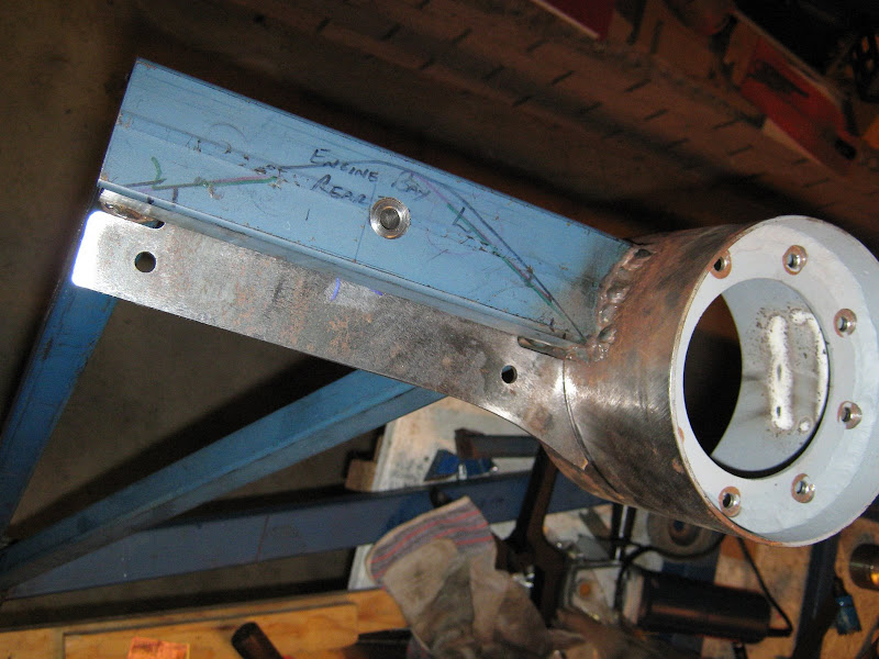
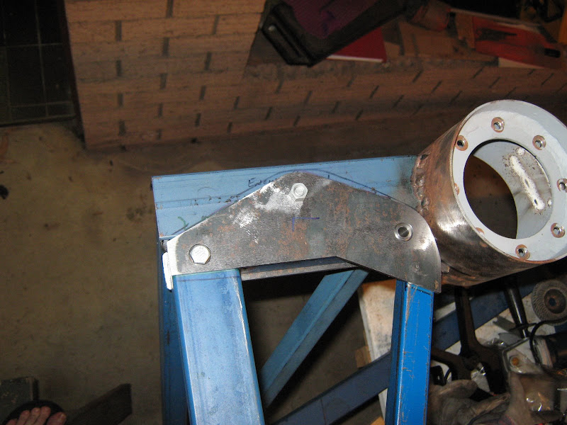

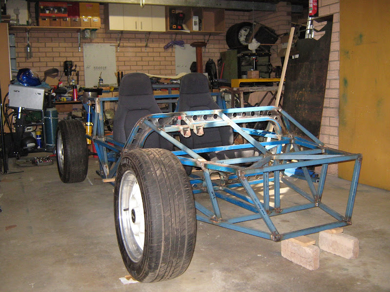


 Cue mixture of concern and pissing-herself -laughter from SWMBO as I roll on floor clutching toe!
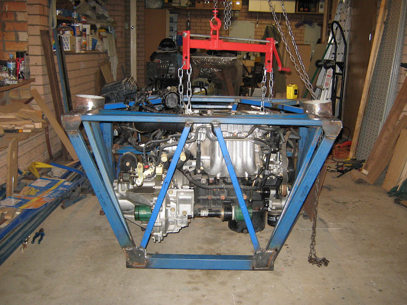
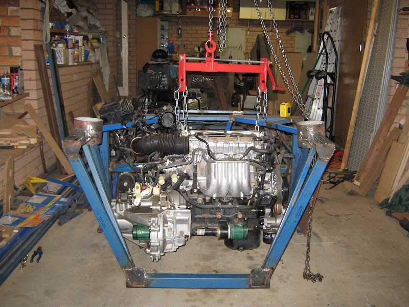
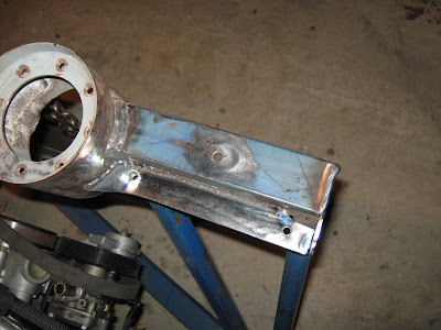
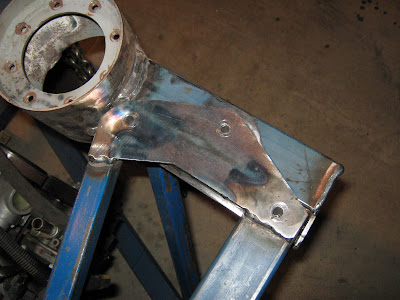

 Thanks again Paul.