Russell
|
| posted on 7/12/20 at 05:19 PM |

|
|
Or to use another cliche, it's better to make a bad decision than no decision. At least a bad decision can put you in a place to see what needs
doing to make it right. No decision gets you... well... nowhere!
I love what you're doing John, it's a hugely enjoyable read and I can't wait to see how this turns out. I know it will be ace!
I'm a bilingual illiterate. I can't read in two languages.
|
|
|
|
|
John Bonnett
|
| posted on 7/12/20 at 06:14 PM |
|
|
quote:
Originally posted by Russell
Or to use another cliche, it's better to make a bad decision than no decision. At least a bad decision can put you in a place to see what needs
doing to make it right. No decision gets you... well... nowhere!
I love what you're doing John, it's a hugely enjoyable read and I can't wait to see how this turns out. I know it will be ace!
You're a gent Russell and you're spot on with your analogy.
|
|
|
starterman
|
| posted on 7/12/20 at 07:04 PM |
|
|
If only you webbed fingered Devonians would behave and get yourself into Tier One then we could finally catch up 
|
|
|
John Bonnett
|
| posted on 13/12/20 at 04:41 PM |
|
|
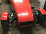
With the partial floor finished and ready to weld in, my thoughts turned to body shape and the wire frame buck and that's where most of the time
this week has been expended. I have also remodelled the tubular body frame which I think I mentioned was on my mind to do. The longitudinal tubes have
been cut and shut to give an 18 degree slope for the continuation tube and the top of the B post angled backwards.
At present the rear of the wire frame extends 500mm rearward of the rear of the rear tyre, slightly less than a wheel diameter. This might be slightly
too much because I remember EB suggested half a wheel diameter as an ideal overhang. Half a wheel overhang might suit the front better as well.
Here are a few photos to bring you up to date.


|
|
|
ettore bugatti
|
| posted on 14/12/20 at 10:20 AM |
|
|
That is a big fuel tank!
I always like the bigger overview pictures, I hope to see more of how the wireframe evolves.
A youtube watch tip is Avalon King Zero Supercar build by Casey Putsch, you probably already seen it if youtube got their algorithms right:
https://youtube.com/playlist?list=PLt3Qhjl4f69JgMNDes8dFqiFu7tHRUzvw
|
|
|
John Bonnett
|
| posted on 14/12/20 at 02:01 PM |
|
|
quote:
Originally posted by ettore bugatti
That is a big fuel tank!
I always like the bigger overview pictures, I hope to see more of how the wireframe evolves.
A youtube watch tip is Avalon King Zero Supercar build by Casey Putsch, you probably already seen it if youtube got their algorithms right:
https://youtube.com/playlist?list=PLt3Qhjl4f69JgMNDes8dFqiFu7tHRUzvw
Thank you for the link. I hadn't seen the series so a good find.
The tank which is from a Focus is big and I may not be able to use it. The one from the Fiesta is still in the car so probably the the thing to do is
to remove it and see if that would fit in any better, it certainly has a smaller capacity. I really don't want the tank where I'd placed
it. I'd much prefer it to be below the boot floor rearward of the axle.
|
|
|
John Bonnett
|
| posted on 20/12/20 at 04:12 PM |
|
|
Not a great deal to show for a week's work but nevertheless progress has been made.
I have felt for some time that the Fiesta rear window would suit my car so the plan was to remove the glass and then the rear window aperture from the
donor car. What a great source of parts this is proving to be and an excellent purchase.
Unlike the front screen which is bonded in the rear uses a rubber seal which made removing the glass an easy task. Once out the plasma cutter came
into its own in cutting out the aperture. This is double skinned coming together and spot welded to form the flange over which the rubber seal fits.
Once relieved of its supporting structure the aperture was very wobbly and clearly would need stabilising which could be quite tricky. Care is needed
to ensure that the glass sits perfectly after the bracing has been welded in.
But before all that the aperture was laid in place and first impressions were that it will indeed fit in nicely.
At this stage it might be useful to introduce the bending beam that is great for bending thin wall tube without buckling or any flattening on the
bends. My first one of these that I have had for thirty years had been seriously attacked by wood worm and sadly snapped when put into use. A new
piece of 4 x 2 air dried oak was purchased and at the first attempt of bending 1" diameter tube it promptly split downwards. Very disappointing
considering how much work the previous one had done without complaint. The problem was solved by fabricating a very tight fitting collar that was
tapped into place over the end of the beam.
I'm currently bending 5/8" diameter tubing to fit between the two skins of the window aperture and once in place will be welded in.
I'm sure many of you will remember my friend and mentor TrevD who used to be on this forum. He sent me a couple of photos of a DB5 Zagato
without the panels. Trev told me that the tubes used on the frame are only 1/2" diameter which makes my frame look like a roll cage. Time to
think how I continue with it!


|
|
|
John Bonnett
|
| posted on 24/12/20 at 03:04 PM |
|
|
At some point very soon I shall have to make the inner rear wings or wheel boxes for my car and this involves either substantial shrinking or a lot of
wheeling to achieve the necessary curvature. To avoid ending up with a paper thin panel which it would be if I just wheeled it I'm going to
attempt the technique of tuck shrinking which is carried out on a hardwood tree stump with a bowl hollowed out on its top face. I've seen this
ably demonstrated many times by the likes of Wray Shelin but although I did prepare a stump some years ago for the purpose I have never actually had a
go at it. So, time for a little play using a piece of scrap steel sheet.
I'm sure many of you have seen it done but for those who haven't, the idea is to place about 50mm of the sheet on the flat portion of the
wood and using a heavy hammer, place blows on a line just over the edge of the bowl. This stretches the metal in the area of the hammer blows which
causes tucks to appear on the adjacent material that is placed on the flat. The next bit is the tricky bit which involves trapping the tuck so that it
has nowhere to go with hammer blows at the apex and at the sides which accentuates the triangle. Once this is done the tucks can be hammered down and
the material has no option but to shrink inside itself. The hammer marks are then smoothed out on the wheeling machine.
The experiment went well but steel is hard work. The idea is to make only half the curve on this part and then make the continuation piece welding it
on the curve.
So, that probably wraps things up for a few days but in the meantime I would just like to thank everyone who throughout the year has taken the time to
read my thread and for the really helpful and constructive comments that have been made. A very happy Christmas to you all.
John


|
|
|
HowardB
|
| posted on 24/12/20 at 04:57 PM |
|
|
wow - as ever this is an incredible thread and highly educational.
thank you and happy Christmas
Howard
Fisher Fury was 2000 Zetec - now a 1600 (it Lives again  and goes zoom) and goes zoom)
|
|
|
John Bonnett
|
| posted on 24/12/20 at 06:07 PM |
|
|
quote:
Originally posted by HowardB
wow - as ever this is an incredible thread and highly educational.
thank you and happy Christmas
That's very kind of you Howard, thank you and of course the same to you.
As far as educational is concerned I'm not sure about that other than to say that I am probably the one being educated and learning as I go
along. I'm very much a novice at metal shaping and apart from guidance from my mentor TrevD I'm just copying what I've seen
demonstrated on YouTube. I think what it does show is that making a nice panel is well within the capabilities of anyone who wants to have a go at it
without the need to buy specialist equipment.
|
|
|
steve m
|
| posted on 24/12/20 at 07:27 PM |
|
|
" I am probably the one being educated and learning as I go along. I'm very much a novice at metal shaping"
Says the man that has already made an Aluminium body for a GT6, that looks frigging excellent ????
I think John is underestimating his skill facto a bit
steve
Thats was probably spelt wrong, or had some grammer, that the "grammer police have to have a moan at
|
|
|
John Bonnett
|
| posted on 1/1/21 at 10:41 AM |
|
|
Not Sunday evening I realise but time for a little update.
I mentioned previously that I have had a little play with tuck shrinking so I knew the path ahead was going to get very physical. And it did!
The plan was to make the arch in two parts with a welded join on the curve to avoid distortion when welding. Following the curve I marked a line 50mm
in which would be the path of the hammer blows. I'd prepared a stump quite a few years ago but never used it. Having it ready saved quite a bit
of time. The idea is to place the area between the line and the and the outside edge on the flat part of the stump and hammer over the void of the
hollowed out section. This has the effect of stretching the material where the hammer has struck and causing a tuck to appear on the adjacent flat
area.Even using the heaviest hammer I could lay my hands on it was damned hard work and not easy to raise the tucks. But we got there in the end and
the two pieces, one for each side were done. I had to make a simple buck and a bit of wheeling and further shrinking produced a reasonable fit on the
buck. The next piece was flat and for different reasons proved equally difficult. I put a 10 degree fold 15mm wide along the length and using the hand
shrinker began to pull it into a curved section. I'm not sure if this was the best way but it was the only way I could think of doing it. I also
wheeled in some shape which smoothed the folded crease and helped with the bending procedure. With the best fit possible of the two parts on the buck
they were marked and trimmed so that they butted up together. They were then TIG welded. I was hoping for a no filler (fusion) weld but a less than
perfect no gap between the panels and limited TIG welding skill with 1mm steel prevented it. But all in all it went well with good penetration and not
too much to sand and planish. There was also minimal distortion which was a relief. The final photo shows the assembly with more finishing needed but
pretty nearly there.
The horizontal section stops short of the tyre and I intend to bridge the gap to within half an inch of the outer wing with flat wing liner material.
The gapp will be covered by a push on rubber section.


|
|
|
John Bonnett
|
| posted on 2/1/21 at 05:37 PM |
|
|
I've now started the arch for the other side with the vertical piece now ready and fitting the buck very nicely. The photo shows an area in the
middle of the panel that has been heated. In error I had wheeled too much shape into this area so I copied a technique for heat shrinking that
I'd seen Wray Shelin using. It is just a question of heating the area up and tapping it down with a flipper and it worked very well. I just
thought I'd share that with you in case it might be of help.

|
|
|
John Bonnett
|
| posted on 3/1/21 at 05:17 PM |
|
|
I've spent a while planishing the first arch and for a first attempt I don't think it is too shabby. The shape is pretty even with no
obvious bumps or lows. Evidence of the weld has all but disappeared so I'll probably stop there before I damage the panel. Rather than tipping a
flange on the flat edge which I had planned to do, I'll joddle a step to accommodate the wing liner material which will probably be rivetted to
it.
The second piece for the second arch is under way but will need several hours more work before it is ready to be welded together.


|
|
|
Deckman001
|
| posted on 3/1/21 at 08:23 PM |
|
|
Hi John,
Looking good as usual, keep it up as your build always cheers people up seeing how good your doing it
Jason
|
|
|
John Bonnett
|
| posted on 3/1/21 at 09:49 PM |
|
|
quote:
Originally posted by Deckman001
Hi John,
Looking good as usual, keep it up as your build always cheers people up seeing how good your doing it
Jason
Thank you Jason and if that's true I'm really pleased. What I'm actually trying to do, apart from building a car for which I have no
plans, is to show that anyone can, with no formal training and the minimum of specialist tools, do amazing things with a flat sheet of metal if they
really want to. There is something very creative in forming a nice double curvature panel and I hope that in my photos and a bit of blurb to go with
them they convey the pleasure and enjoyment that I have for the hobby and if this inspires others to have a go themselves I would be delighted.
|
|
|
John Bonnett
|
| posted on 6/1/21 at 04:21 PM |
|
|
The two inner arches are finished now with the exception of a few extraneous holes to fill and I have to say I'm really pleased with the result.
Although harder to work than 1050 aluminium, steel is far more forgiving and generally goes where you want it to without splitting when stretching.
And welding is easy too. I've just got to work out how to mount them.

|
|
|
HowardB
|
| posted on 6/1/21 at 04:57 PM |
|
|
quote:
Originally posted by John Bonnett
The two inner arches are finished now with the exception of a few extraneous holes to fill and I have to say I'm really pleased with the result.
Although harder to work than 1050 aluminium, steel is far more forgiving and generally goes where you want it to without splitting when stretching.
And welding is easy too. I've just got to work out how to mount them.
That is so impressive - you must have incredible patience and skill.
I look forward to the updates each day
Howard
Fisher Fury was 2000 Zetec - now a 1600 (it Lives again and goes zoom)
|
|
|
John Bonnett
|
| posted on 6/1/21 at 06:45 PM |
|
|
That is so impressive - you must have incredible patience and skill.
I look forward to the updates each day
I once said the same thing to a model engineer friend of mine Howard and I'll never forget his reply. He said that if you enjoy what
you're doing you don't need patience and I think that was so true. Today I have found a bit trying but that was just because of the cold
rather than any lack of enthusiasm.
|
|
|
jps
|
| posted on 7/1/21 at 09:10 AM |
|
|
Fascinating to see, John - you are highly skilled no matter what you say!
As you mentioned, the frame you are putting in looks more like a rollcage than a simple frame and I assume the original Kitten GRP body wasn't
srtuctural - and the chassis did all the hard work in that respect. Will the inner arches (and other parts of your body) be structural as I assume
they are in a monocoque/unibody car?
|
|
|
John Bonnett
|
| posted on 7/1/21 at 09:23 AM |
|
|
quote:
Originally posted by jps
Fascinating to see, John - you are highly skilled no matter what you say!
As you mentioned, the frame you are putting in looks more like a rollcage than a simple frame and I assume the original Kitten GRP body wasn't
srtuctural - and the chassis did all the hard work in that respect. Will the inner arches (and other parts of your body) be structural as I assume
they are in a monocoque/unibody car?
My previous project was restoring a Ginetta G15 and even the die hard enthusiast of the marque referred to the chassis as a farm gate. By comparison,
the Kitten chassis is beautifully designed and very stiff needing no additional help from the body. So in answer to your question no, none of the
bodywork is structural. I beefed up the windscreen frame and the B posts mainly to give some protection in the event of a crash. I could have made the
inner wings in aluminium but just felt that steel would be more durable in that situation.
[Edited on 7/1/21 by John Bonnett]
|
|
|
John Bonnett
|
| posted on 13/1/21 at 06:25 PM |
|
|
Unfortunately I had to extend the inner wings downwards front and rear which could have been avoided with more careful planning and this added
considerable time to the job of finishing them. But all done now and one is mounted in position. The gap between the steel and the outer wing will be
filled with wing liner material which I now have in stock. It will be riveted in place and supported midway by an L section formed to match the
required curvature.


[Edited on 13/1/21 by John Bonnett]
|
|
|
ettore bugatti
|
| posted on 13/1/21 at 07:15 PM |
|
|
Looks nice!
Must be good practice for panel beating forming skills.
How is the wire frame developing?
|
|
|
John Bonnett
|
| posted on 13/1/21 at 07:57 PM |
|
|
quote:
Originally posted by ettore bugatti
Looks nice!
Must be good practice for panel beating forming skills.
How is the wire frame developing?
The only bit of the wire frame I've done so far is the wheel arch and I'm hoping to incorporate this into wired edges of the aluminum
wings. The wire also continues around the back joining the two bits of the wire frame together. The only parts that probably will not need altering
are the wheel arch sections of the wire frame. The rest will need re-forming. Before progressing further I need to establish where the main frame
rails are going to be and then the buck can be made and tacked to them. It's a bit of a chicken and egg situation but that's the way
I'm choosing to tackle it. I'm under no delusions how difficult it is going to be forming the buck and that will be a challenge in
itself.
I certainly was nice to do a bit of metal shaping and working with steel proved a pleasant change from aluminium. The planishing hammer that some
regard as just a toy made light work of the job and to my mind is worth every penny I paid for it. It even formed the domed tops to the shock absorber
towers out of 2mm mild steel. A great bit of kit for not too much money.


|
|
|
ettore bugatti
|
| posted on 13/1/21 at 09:06 PM |
|
|
I like the concept/idea of just using hammers to form a body.
Apparently, the Italians only used hammers for their coachwork in the fifties/sixties.
Oh, and the Japanese
https://youtu.be/FZNFsbDDOPs
|
|
|