roadrunner
|
| posted on 4/5/20 at 06:05 PM |

|
|
ZX10R wiring help
Evening all.
I've been working on my wiring now for a couple of weeks.
It's been slow going after leaving it for so long but I've managed to get everything connected up.
I'm using part of the old car loom for lights and indicators and ignition side of thing's.
The bike loom has had all the unnecessary bits removed.
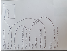
I've connected the car ignition to the bike side using this guide
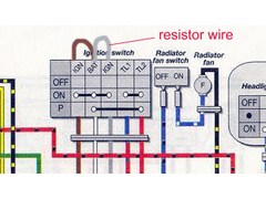 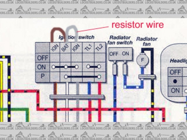
Rescued attachment ignition block.jpg
My problem is that when I connect the bike battery positive cable to the battery the zx10 clocks come on even though the ignition is switched off.
The engine turns over as it should when using the ignition. (Can't start it yet as I have no manifold and the pump isn't fitted)
The only way I can stop this from happening is pulling the car wire's out of the bike loom. Even then the clocks does a needle sweep but
doesn't actually come on.
I need advice if I'm to move forward.
Thanks in advance
Brad.
|
|
|
|
|
russbost
|
| posted on 5/5/20 at 08:04 AM |
|
|
Brad, If I'm understanding correctly what the brown & wire loop wires are connected to, then surely you are effectively by passing the
ignition switch, taking the permanent +ve from the battery & feeding it direct to ecu via the resistor wire & direct to everything else on the
brown wire - it looks as tho' you're simply bridging the switch?
Surely the resistor should be on the outgoing side of the ign sw. inline with the ecu wire & I don't follow the purpose of the brown wire at
all?
I no longer run Furore Products or Furore Cars Ltd, but would still highly recommend them for Acewell dashes, projector headlights, dominator
headlights, indicators, mirrors etc, best prices in the UK! Take a look at http://www.furoreproducts.co.uk/ or find more parts on Ebay, user names
furoreltd & furoreproducts, discounts available for LCB users.
Don't forget Stainless Steel Braided brake hoses, made to your exact requirements in any of around 16 colours.
http://shop.ebay.co.uk/furoreproducts/m.html?_dmd=1&_ipg=50&_sop=12&_rdc=1
|
NOTE:This user is registered as a LocostBuilders trader and may offer commercial services to other users
|
roadrunner
|
| posted on 5/5/20 at 09:01 AM |
|
|
Morning Russ.
What I'm trying to do is use the car ignition switch to start and run the bike engine and clocks.
This is my simplified wiring diagram. I'm not really hot at electrics.
 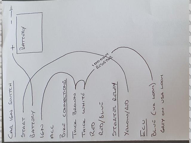
Arrgghh
Hope it makes sense.
Brad
|
|
|
russbost
|
| posted on 5/5/20 at 09:34 AM |
|
|
Electrics are fairly simple as long as you keep them simple & follow logic, a supply will always find it's easiest route to earth if there
is one! It's electronics that does my head in, it's clearly some form of black magic!
Your second diagram appears to make sense, it's the first one I'm struggling with, what are the small "loop" wires in brown
& white intended to do? in your diagram they appear to by pass the switch, which would explain your problem.
At the ign sw as per second diagram, you should have a feed IN from the battery, you then need to look at what wires go live in the various Acc, Ign,
Start positions with nothing else connected to the switch (if you don't disconnect everything else then there is always the possibility that
you'll be recording voltage "fed back" thro' another circuit). The wire that comes live in the Acc position, you don't
need, the wire(s) that comes live on ign., from dig I would expect there to be 2 of these, use one to feed your 100 ohm resistor & subsequently
the ECU, use the other to feed the rest of ign circuits - check that both wires remain live when key held in the start position. If you are concerned
about the current handling ability of the switch then use both those wires together to feed all ign live circuits & just take the 100 ohm resistor
wire as a "spur" off that main ign live feed
Then confirm which wire comes live ONLY when in the start position, & that is fed to your starter relay, yellow/red wire
Not certain about the ZX10R, but the ZZR1400 loom, the white wire (main feed from battery/solenoid) as well as feeding ign sw. also feeds a fuse on
fuse box 2 which feeds the clocks, I'm guessing there is an actual clock on there which therefore needs a permanent feed or there is some other
"memory" requirement withion the clocks - I don't use them so never got into that part of the loom
I no longer run Furore Products or Furore Cars Ltd, but would still highly recommend them for Acewell dashes, projector headlights, dominator
headlights, indicators, mirrors etc, best prices in the UK! Take a look at http://www.furoreproducts.co.uk/ or find more parts on Ebay, user names
furoreltd & furoreproducts, discounts available for LCB users.
Don't forget Stainless Steel Braided brake hoses, made to your exact requirements in any of around 16 colours.
http://shop.ebay.co.uk/furoreproducts/m.html?_dmd=1&_ipg=50&_sop=12&_rdc=1
|
NOTE:This user is registered as a LocostBuilders trader and may offer commercial services to other users
|
roadrunner
|
| posted on 5/5/20 at 10:43 AM |
|
|
Thanks Russ.
I will have a re think.
The first diagram was from an old thread that someone else posted and I have copied from that.
The second picture is of what I have actually done utilising the first diagram.
Regards
Brad
|
|
|
russbost
|
| posted on 5/5/20 at 12:25 PM |
|
|
Just had another thought. You would expect some activity from the dash when you connect the battery due to the permanent feed from the 2nd fuse box,
white wire (assuming same as ZZR). It depends what you mean by "the clocks come on" - if it is only a clock readout then you would expect
that, but if it's more then obviously there is a prob elsewhere.
Easy enough to check if there is power on the brown wire with ign off - that should only be live when ign on.
HTH
I no longer run Furore Products or Furore Cars Ltd, but would still highly recommend them for Acewell dashes, projector headlights, dominator
headlights, indicators, mirrors etc, best prices in the UK! Take a look at http://www.furoreproducts.co.uk/ or find more parts on Ebay, user names
furoreltd & furoreproducts, discounts available for LCB users.
Don't forget Stainless Steel Braided brake hoses, made to your exact requirements in any of around 16 colours.
http://shop.ebay.co.uk/furoreproducts/m.html?_dmd=1&_ipg=50&_sop=12&_rdc=1
|
NOTE:This user is registered as a LocostBuilders trader and may offer commercial services to other users
|
roadrunner
|
| posted on 5/5/20 at 12:30 PM |
|
|
When all the connections are apart and I connect the bike loom to the battery it only does a basic needle sweep.
So like you say it's just for the basic function of the clock.
I'm going to test the voltages of all the wiring to gain more info on how to connect this up.
Forgot to mention that the wiring on the zx10r is nearly identical to the zx9 I had previously so should be the same with the zzr1400.

[Edited on 5/5/20 by roadrunner]
|
|
|
roadrunner
|
| posted on 5/5/20 at 01:10 PM |
|
|
I've tested the voltages on both looms connecting each loom individually to the battery.
Zx10 loom.
The thick white is a permanent 12v feed and comes from the rectifier.
The brown shows no voltage at all.
Car loom at ignition switch.
With ignition key switched on.
Start terminal shows 12v.
Ignition terminal, no voltage but shows a small voltage when trying to start engine.
ACC shows no voltage.
So obviously I need to ignore the thick white wire on the zx10r loom and just connect to the brown. Or do I connect the resistor to the white wire.
Don't understand the voltages on the ign switch though.
[Edited on 5/5/20 by roadrunner]
|
|
|
roadrunner
|
| posted on 9/5/20 at 06:15 PM |
|
|
Had to strip out all the old wiring today and trace back the wiring as I still had no voltage ignition feed to the zx10 side.
Found that my white feed wire wasn't connected to anything.
Don't know why as everything worked when the zx9 was in.
Anyway all is good now. Just need to check stop button and start button wiring and side stand to see if I can get a spark.
|
|
|
roadrunner
|
| posted on 14/5/20 at 06:52 PM |
|
|
Just to finalise this thread.
For anyone fitting a ZX10R engine and loom this is what you need to do.
The best route to take is to buy an American loom and ecu as to miss off the immobiliser.
I had a UK loom but purchased an American ecu and Power Commander.
I still needed to fit a 100ohm resistor.
On the American loom you connect the resistor to the grey wire and up to a switched live. On the UK loom its a blue wire from the ecu that goes to the
immobiliser. Cut from immobiliser and splice in the resistor and connect to a switched live.
The side stand switch has two wires, just connect these together.
The engine kill switch has two wires, connect these together.
The engine start button is where I was getting it wrong.
You have to use these two wires with a start button to get your spark. I just extended them to an illuminated start button as one of the wire's
has a 12v current.
Then for anyone wanting to have a fan override switch.
On the large relay box there is three connectors. One of them is for the fan. It has a blue wire and a green wire. If you splice in wires from them
to a basic switch it works fine.
HTH
|
|
|