designer
|
| posted on 19/11/23 at 11:31 AM |

|
|
3D - Solidworks
Anyone around Leeds area do 3D drawing, as I have decided that I am rubbish at it and might as well try to nail jelly to the ceiling!!
I'm after a chassis drawing in 'any' format, as long as engineering companies can read it.
|
|
|
|
|
coyoteboy
|
| posted on 19/11/23 at 11:42 AM |
|
|
quote:
Originally posted by designer
Anyone around Leeds area do 3D drawing, as I have decided that I am rubbish at it and might as well try to nail jelly to the ceiling!!
I'm after a chassis drawing in 'any' format, as long as engineering companies can read it.
A chassis drawing is not an easy task to be fair. It's an easy job to do in a way that looks good but isn't good for manufacture (having
seen a few years of formula student students through it). You need to work with your supplier to know how they want it drawn.
|
|
|
designer
|
| posted on 19/11/23 at 12:21 PM |
|
|
I certainly know that it isn't easy. Been messing for a while.
It's the round stock and the curves that are driving me mad.
|
|
|
coyoteboy
|
| posted on 19/11/23 at 12:31 PM |
|
|
quote:
Originally posted by designer
I certainly know that it isn't easy. Been messing for a while.
It's the round stock and the curves that are driving me mad.
Have you followed any of the formula student tutorials on YouTube? Search fsae chassis design tutorial.
|
|
|
bi22le
|
| posted on 19/11/23 at 04:28 PM |
|
|
Is you problem drawing the parts in 3D or creating the 2D drawings to get the parts controlled and made?
I use solid works everyday for pretty complex geometry and I could imagine a whole chassis with individual part cutting list etc being a fair
challenge.
If I was going to approach it I would assign sub assemblies in the chassis. For example main floor pan, 2nd ladder frame and triangulation
construction, remaining front engine and cross bracing, rear diff carrier and finally roll cage.
This will help with keeping your interfaces down to a minimum in the top level General assembly and provide an easy path for drawing, jigging and
geometric tolerancing.
Good luck.
Track days ARE the best thing since sliced bread, until I get a supercharger that is!
Please read my ring story:
http://www.locostbuilders.co.uk/forum/13/viewthread.php?tid=139152&page=1
Me doing a sub 56sec lap around Brands Indy. I need a geo set up! http://www.youtube.com/watch?v=EHksfvIGB3I
|
|
|
Sam_68
|
| posted on 19/11/23 at 08:16 PM |
|
|
quote:
Originally posted by designerI'm after a chassis drawing in 'any' format, as long as engineering companies can read it.
Does it have to be in Solidworks?
How will it be fabricated - are you looking to have all the tubes CNC cut (note: this only makes sense for large productions runs, otherwise
programming/set-up time vastly outweighs the convenience) or traditionally, by hand?
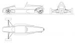
I've done spaceframes before, but I work in 3D AutoCAD.
With AutoCAD, I've (somewhere, if I can find it again - I've changed my computer since doing the last one) got an AutoLISP routine
that does 'developments' of tubes so that you can print a paper template that you then wrap around the tube to give the profile for
fishmouths, if you're fabricating the chassis manually.
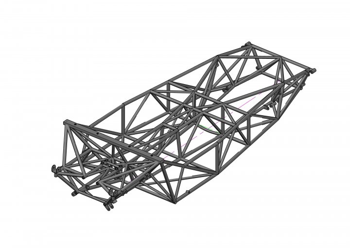
This was pretty much all round tube, and quite complex (it largely used tetrahedrons instead of 2D triangulated 'trusses', which was a
nightmare to fabricate by hand, but the ultimate intention was series production using CNC cut tubes):
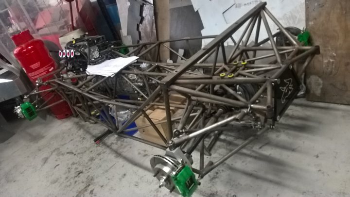
Along with all the individual component drawings (brackets and machined fittings, etc., and in that case as well as dimensioned scale orthographic
drawings, we also printed full size drawings of each planar frame, as templates) it's a non-trivial task, though (hence expensive, if you're
paying for it).
|
|
|
Mr Whippy
|
| posted on 20/11/23 at 07:36 AM |
|
|
Don't use round tube, there's not much of an advantage in using it unless you have a the right tools for cutting the joints and for DIY
it's just a total pain.
|
|
|
Sam_68
|
| posted on 20/11/23 at 08:35 AM |
|
|
quote:
Originally posted by Mr Whippy
Don't use round tube, there's not much of an advantage in using it unless you have a the right tools for cutting the joints and for DIY
it's just a total pain.
I'd agree with this.
You see much comment on the internet about the better properties of round tube in torsion: if it's properly triangulated this is more or
less irrelevant, because each individual tube should be in near perfect tension or compression (and where it isn't, it's more likely to be
bending than torsion that's your problem, which square tube is better at, anyway).
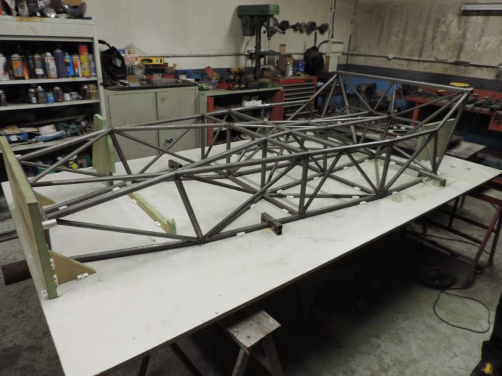
We used all round-tube on the above chassis because the chap who was paying the bills insisted on it (against my grumblings!), and because we were
expecting the tubes to be CNC laser cut. We did manage to get very good stiffness for very low weight, but that was at the cost of a lot of
complexity, and it was a pig of a thing to fabricate.
[Edited on 20/11/23 by Sam_68]
|
|
|
coyoteboy
|
| posted on 20/11/23 at 09:45 AM |
|
|
To be fair, there are places who will laser cut one offs fairly cheaply but the tools to fishmouth are cheap and easy to use. If countless teams of
first year engineering students with zero practical skill can make a chassis with 1mm deviation end to end, anyone can 🤣
|
|
|
designer
|
| posted on 20/11/23 at 10:50 AM |
|
|
It's to be made from round because most of it will be visible and we all know that round looks better than square, even though it take longer,
and costs more, to make.
I have designed and built chassis from square tube on my old Autocad 2000, and now use ProgeCAD as 200 won't run on 'modern' software,
but this 3D stuff I think is beyond me at my age! Have got Fusion, Sketchup and the Dessault 3D experient thing; I am totally lost!!
The chassis will be low powered (400-500cc scooter) and will consist of no more than 25 individual pieces, of which some are square and angle as they
will be buried in the middle and under the seat.
I predict a one-off chassis will cost £800/900 and I can deal with that.
|
|
|
nick205
|
| posted on 20/11/23 at 11:59 AM |
|
|
My memory of 3D CAD modelling (early 2000's) I had a go at modelling a Locost chassis.
Modelled each Part and then built the parts into and Assembly. Labourious and in the Assembly you'd need to define each and every joint with
it's weld specification. If you want to hand the model over to a manufacturer.
As mentioned above you need to be on very good terms with your chosen manufacturer (unless that's you) to know exactly how to spec it in the way
they understand and can achieve.
Tolerances - you'll need to allow tolerances for the manufacturer to be within. Nobody can get things spot on and will probably be offended if
you ask/expect them to.
|
|
|
pigeondave
|
| posted on 20/11/23 at 01:32 PM |
|
|
quote:
Originally posted by Sam_68
We did manage to get very good stiffness for very low weight, but that was at the cost of a lot of complexity, and it was a pig of a thing to
fabricate.
[Edited on 20/11/23 by Sam_68]
Got any numbers please? How big is very good?
|
|
|
Sam_68
|
| posted on 20/11/23 at 06:13 PM |
|
|
quote:
Originally posted by pigeondave
Got any numbers please? How big is very good?
Roughly 3,800Nm/degree for a chassis weight of 59 kilos, which calculates to a stiffness:weight of about 15.5g/Nm/deg.
For comparison, according to the Wesley Linton thesis, a 'normal' Locost chassis is about 88g/Nm/deg. (although my experience is that
they're a bit better than that, at about 50g/Nm/deg) and his optimised design gave 20.99g/Nm/deg.
I could have achieved better by following the Costin patented arrangement for the cockpit section, but the man with the chequebook wouldn't let
me (on account of he wanted to be able to fit separate, adjustable seats).
|
|
|
pigeondave
|
| posted on 20/11/23 at 10:48 PM |
|
|
quote:
Originally posted by Sam_68
Roughly 3,800Nm/degree for a chassis weight of 59 kilos, which calculates to a stiffness:weight of about 15.5g/Nm/deg.
Many thanks
|
|
|