
Balance Bar Puzzle
xxx - 16/6/12 at 06:09 PM
Hi guys,
Replacing a master cylinder on my locost has become a bit of a nightmare. I have two new willwood 0.75" master cyclinders bolted into the
bulkhead...these are direct replacements to what was there before. I have also bought a new balance bar as the thread on the old one was knackered due
to the bush (on the brake pedal) hitting the thread repeatedly....I presume this means it wasn't setup properly in the first place?
Anyway after a couple of fraustrating hours down the footwell I have manged to get the new balance bar in place. However I really cant get my head
around how the whole assembly is working.
I have tried to follow the concept detailed on the rally design website:
http://www.rallydesign.co.uk/balancebar.php
I have screwed the rear push-rod into the clevis as far as it will go and the front push-rod roughly half that distance. I have then screwed the
clevii onto the balance bar so that both push-rods are parallel.
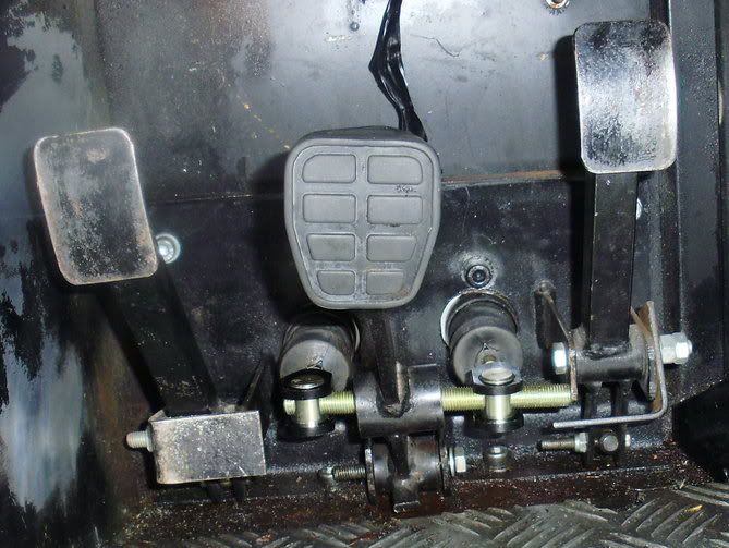
When I press the pedal the bush jams against the threaded part of the balance bar....this cant be correct surely?
Also the spherical can moved left and right within the bush. This means the whole assembly is pretty slack and must prevent constant brake balance?
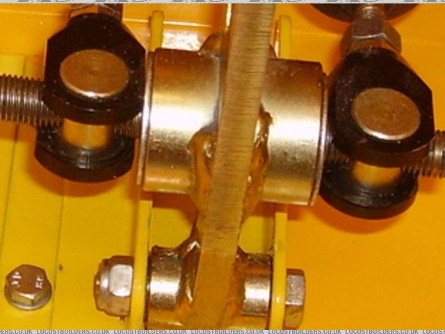
Here is a couple of pics of the installation (note Left=Rear Right=Front):
Natural Position:
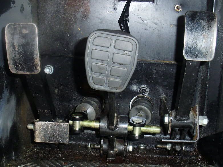
Bar pushed right?
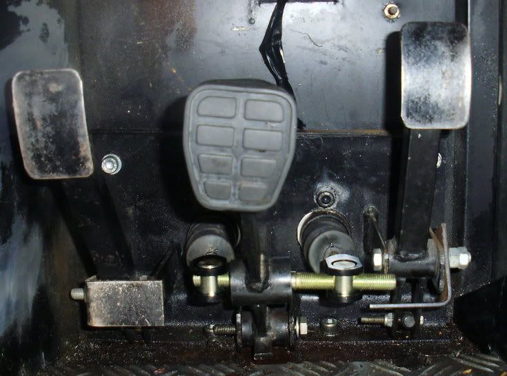
Bar pushed left?
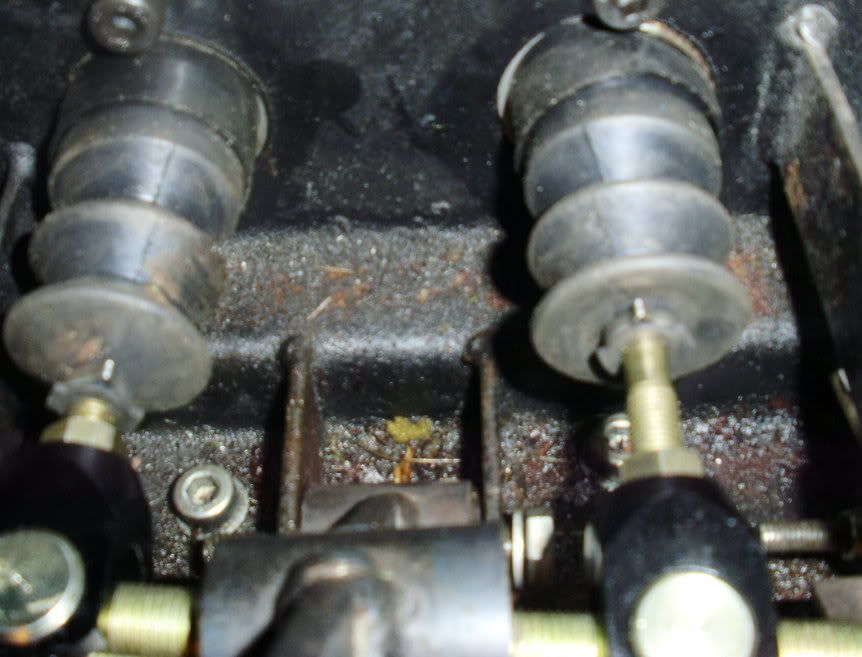
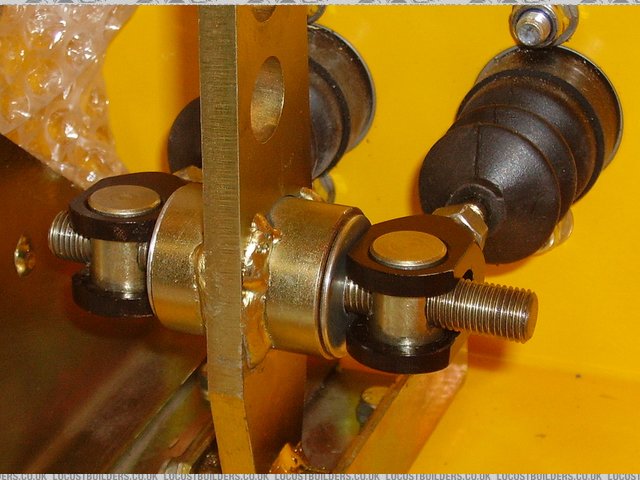
Top view showing the push-rod into the clevis (note boots arent in comparable positions)
Does anyone know what I need to do in order to stop the pedal bush hitting the threaded bar during braking? Have I done something wrong or is there a
fundemental problem with the setup?
I believe the push-rods should always remain parallel and you screw the bar left/right to bias one clevis towards the spherical to give the
adjustment?
In my case I obviously want to bias the brakes to the front. Therefore the right hand clevis needs to be furthest towards the driver and slightly
further away from the spherical than the left hand clevis?
Sorry for the detailled post, its quite hard to explain especially when Im not sure whats going on! Thanks in advance!
MikeRJ - 16/6/12 at 06:28 PM
That is set up incorrectly. The two clevises must be wound up until they are very close (but not tight against) to the tube that holds the spherical
bearing. This both prevents the entire rod shifting around and should allow the mechanism to bind at high angles which will ensure you still have
some brakes should one circuit fail.
Unfortunately your master cylinders are mounted too far apart, which means the push rods will be sitting at an angle with the clevises adjusted
properly.
The bias bar should be adjusted so that it is approximately parallel when the brakes are applied - this may mean it sits at an angle when the pedal
isn't pushed.
[Edited on 16/6/12 by MikeRJ]
theprisioner - 16/6/12 at 06:42 PM
Motorsport-tools (www.motorsport-tools.com) gave me the following advice:
"We would recommend the 0.625 for the front and 0.75 on the rear."
This apperas to be a correct recommendation from reading other threads on the matter. I tried to get similar advice from Rally Design but I could not
get them to reply to my emmails (twice). The advice I was looking for was about cylinders and 4 pot Willwoods. The above company took the trouble to
resond twice. Hope this helps.
stevegough - 16/6/12 at 07:07 PM
Yes, Mike has hit the nail on the head, the basic problem is that the master cylinders are set too far apart. For comparison, here's my balance
bar / pedal box set up. As to a solution - not quite sure, but you definitely need to wind the clevises closer to the pedal bush - this should
be your first action.

And a post - IVA pic showing it lockwired in position.

britishtrident - 16/6/12 at 07:30 PM
Oh dear quite a lot wrong, it looks to as if you need to do a redesign, first of all the distance ( ie in engineering terms pitch ) between
the master cylinder centre lines is are mismatched to the width of cross tube in the pedal, ie n master cylinders are set too far apart.
The pitch of the master cylinders should be only slightly greater than the width of pedal cross tube + width of one of the push rod clevis
fork.
When set up properly with the balance bar straight the sides of the clevis forks should be almost touching the ends of the pedal cross tube,
this is very important as it ensures the system will retain some braking if one hydraulic circuit fails.
it should look more like this
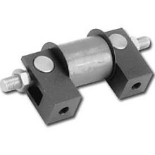
or this

Note how master cylinder push rods are almost parrallel and in line with the master cylinder bores.
More info here
Cobra 289 register
avagolen - 16/6/12 at 07:36 PM
Hi, I can only comment on what I have read and done
I have set mine up, but not tested yet as the car is not running.
The spherical in the tube should be greased and large washers positioned
either side of the tube to reduce the chance of dirt getting in there. The washers should
be large enough to prevent them getting jammed in the tube.
The push rods should be parallel and close to the tube with about 1 mm of float.
The rear push rod / cylinder should pressurise first, becoming a fulcrum for the front cylinder push rod.
Rear short stroke, front long. (spherical closer to the rear pushrod.)
In your setup, so you do not have to reposition your cylinders, I would try and put spacers
between the push rods and the large washers described above, with some room for float,
which would prevent the spherical from moving much side to side within the pedal tube.
Here is a picture of mine, you would need quite thick washers to ensure the 'spacers'
have a reasonable stiffnes to work against without the chance of dishing them.
The spacers would have to work against the pushrod nut face within the limits of the
yoke and the washer.

Balance_bar1

Balance_Bar2
HTH
Len.
xxx - 16/6/12 at 08:04 PM
Spot on, thanks very much guys, very helpful. I knew something was up, but I assumed the previous owner/builder had some idea of how to build the
car....obviously a bad assumption. I better go and check over the rest of the car :s
Sounds like a good excuse to get a shiny obp pedal box to me 
tasmod - 17/6/12 at 09:23 AM
I don't consider Steves setup in the first picture to be correct. It's better in the lockwired version. I've spent some time with
these setups and consider that the kit usually supplied by sellers is flawed. I'll explain.
The locknut is tight up against the black swivel collar effectively locking it or partially so. The locknut should be locked against a small short
sleeve that goes over the threaded portion up to the 'silver' swivel part.
If you look at the version in "britishtridents" post you can just about see what I mean. This would prevent the collar from locking but lock
the bar.
In the lockwired version Steve has wrapped the wire in between the nut creating a 'soft' spacer so it's better.
There should be a small clearance against the pedal of the black swivel pieces and the bar should be straight in the relationship to the cylinders
when the brakes are heavily applied without locknuts. This is achieved by adjusting the pushrods when the pedal is hard applied. Then when the pedal
is at rest, the bar, "with bias", should then be angled slightly. Then the sleeve and locknuts applied to lock the bar.
Lens setup is correct because he hasn't locked it yet.
[Edited on 17-6-12 by tasmod]
tasmod - 17/6/12 at 09:37 AM
Incidentally, fitting the .750 cylinder to the front will give you a 'harder' pedal with shorter travel.
I've experimented with three sizes and went back to .625 as it gave the best 'feel control' but at the expense of travel. I found it
easier to get any stage of braking from light to locked.
This with Wilwood four pots and drum rears.
avagolen - 17/6/12 at 12:15 PM
Thanks Rob for the encouragment.
I agree with locking technique you describe.
I have manufactured some locknuts that have a shoulder on
that will only contact the 'silver' threaded part of the pushrod and not the
black yoke.
Len.
Dusty - 18/6/12 at 04:55 PM
One of the problems is that the bias bar was never intended to be locked. It was supposed to allow adjustability on the fly with a system attached to
the end of the bias bar and terminating in a detent-controlled rotating knob where the driver could reach it and twiddle to alter brake bias front to
rear. As IVA requires it to be locked some are simply adding a nut at each end, the nut bearing against the side of the clevis rather than the barrel
and effectively stopping the clevis from turning to compensate for the changing angulation of the bias bar relative to the pushrod. Either a spacer
collar and nut or a collared nut should be used to lock the barrels.
I can't give 100% to any of the pictures so far shown. A large washer should be between clevis and pedal to prevent the clevis catching in the
brake pedal bias joint housing. It needs to be large enough that it still overlaps the housing at both extremes of angulation of the bias bar. Free
space between clevis's and the pedal housing can be set to allow the bar to fully angle both ways with the bias bearing set central in the pedal
housing. It doesn't need to be more than this and certainly not less. If one side fails and gives no resistance the bar will still lock after
longer pedal travel to allow the remaining cylinder to operate.
The drawing is roughly what my setup has ended up like although if I really stand on the pedal the bias bar moves further forward on the front M/c
side while the rear side stays put. (And all four wheels lock)
Anyone see a problem please criticise.
[img]

Bias setup.
[/img]
FuryRebuild - 18/6/12 at 05:33 PM
Dusty
You've just clarified something for me - thanks - I now understand how my adjuster will work - it's not about the amount of thread or where
the clevis's (clevii?) sit but where rotating the centerline moves the pivot about.
That's great - means I can be sure I've got it right.
Pity we can't * a thread as "really damn informative"


