
Critique my upright design
mi2jaca - 26/6/19 at 09:18 AM
Hello,
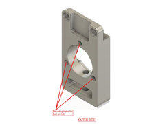
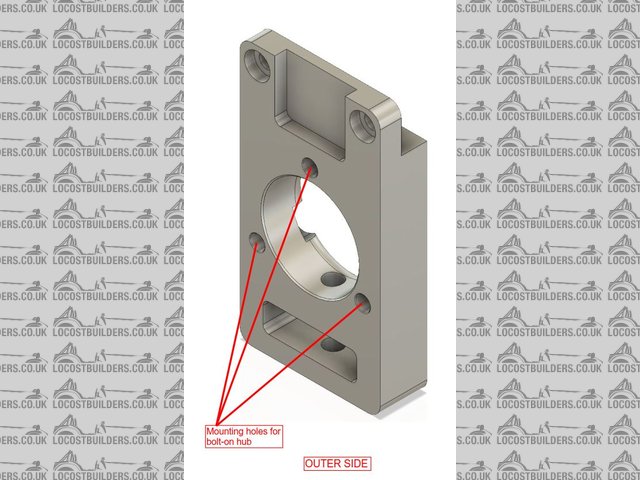
I wrote a previous thread regarding using bolt-on hubs in an upright design (http://www.locostbuilders.co.uk/forum/3/viewthread.php?tid=215025).
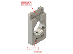
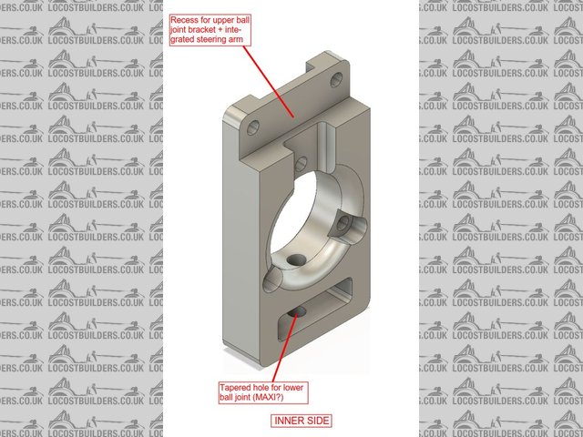
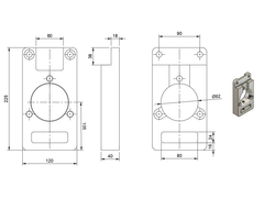
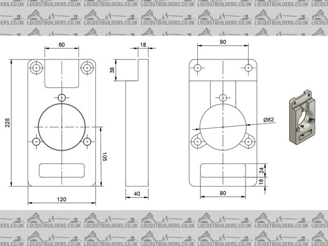
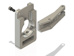
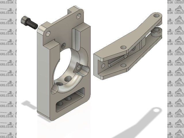
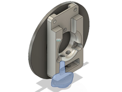
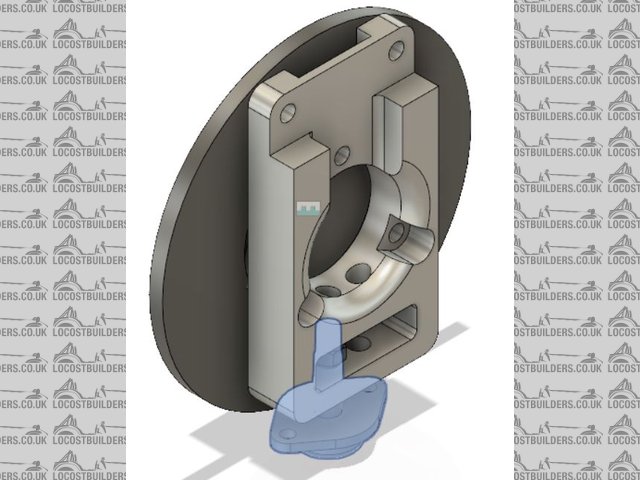
Now its time for the upright to take shape and I thought that I would let the forum have a look and a say. The upper ball joint will be attached from
a bracket to the upright and possibly also incorporate the steering arm or its attachment.
I am trying to make this so that it will fit both sides and so that it will have a minimum of detail for manufacture. Brackets for brake calipers are
not yet included in this design but will probably also be bolt on to the upright.
Right now I am using Austin Maxi ball joints, but are there any other alternatives that might be better, cheaper, more available, future-proof?
Please feel free (relatively  ) to comment.
//Carl
Upright1_rev0 20190626
Upright2_rev0 20190626
Upright3_rev0 20190626
Edit: Added a sketch of some dimensions
[Edited on 26/6/19 by mi2jaca]
nick205 - 26/6/19 at 09:37 AM
Do the parts have to meet any specific rules and/or standards qualification for road use?
Is the material steel, Aluminium alloy (or something else)?
coyoteboy - 26/6/19 at 11:39 AM
Personally not a fan of bracket attachment for major suspension components - the fewer failure points the better - I know plenty of OEMs do it, but
bolted joints need proper stress analysis just as much as the metalwork does. Do you know your two bolts will have sufficient clamping load to prevent
fastener failure or loosening? Having just had a ball joint failure I'm particularly sensitive to this lol. Your bottom ball joint looks like a
fully captured double-shear rose joint - this i love - will the top be?
It looks pretty chunky even if it's alu, but that may be total overkill with a weight expense you don't need.
What grade of alu (if alu) are you using? Are you using straight alu threads or inserts?
Mr Whippy - 26/6/19 at 12:02 PM
but why? when there are alternatives to use, I can't really see the benefit
For example MK Sports cars have -
Sierra ones for just Ł120 a pair
Alloy Cortina ones for Ł360 a pair
Sierra billet alloy ones for Ł550 a pair
Unless you can machine them yourself those must surely be cheaper options?
linky
motivforz - 26/6/19 at 12:41 PM
First thing that jumps out are those sharp internal corners - these are stress raisers and if made out of Aluminium (no endurance limit in fatigue)
then they're going to crack eventually. A nice 3mm radius minimum should be targeted using a 6mm ball nose cutter.
The external rad on the central bore will be difficult to machine (unless being turned?), so a chamfer may be easier if acceptable?
Otherwise can't say without loads whether it'll be ok or not - that'll have to be up to you to determine.
Hope that helps - certainly not meant to be negative!
coyoteboy - 26/6/19 at 12:53 PM
quote:
Originally posted by Mr Whippy
but why? when there are alternatives to use, I can't really see the benefit
For example MK Sports cars have -
Sierra ones for just Ł120 a pair
Alloy Cortina ones for Ł360 a pair
Sierra billet alloy ones for Ł550 a pair
Unless you can machine them yourself those must surely be cheaper options?
linky
I'm guessing that if he's not looking at the normal options, there's a reason. Either he wants to do the design for the experience, or
he wants to do something strange. Pretty sure no-one goes into a suspension design task without first reviewing the off the shelf options?
Re external rad - standard corner rounding cutter? 2.5D milling with ball? Maybe I'm looking at "hard" from a different perspective but
neither of those looks like a difficult option in my mind (though the rad is large).
[Edited on 26/6/19 by coyoteboy]
bozla - 26/6/19 at 01:28 PM
Good point is that you can adjust the kpi with spacers. But as others have pointed out, you can get great parts a very reasonable price. There are
only 2 reasons I can think of for making your own. 1) you can't get the geometry you want from an off the shelf component, 2)weight
reduction.
Rally design offer one (all ali) with hubs, discs, willwood calipers for about 500+tax for a pair. They also go with their locost wishbones or the
longer westfield ones.
I have made my own however as I wanted m/c discs and calipers with 7deg kpi and 7deg caster. Gutted I couldn't get one off the shelf at
reasonable cost.
Drd racing do a ali hub (can take both 108 & 4inch pcd) and weld in stub axle (vauxhall viva based) if you want to go down this route. Rally
design offer ali hubs and bolt on stub axle as well (Cortina based). Drd can even make the uprights to your geometry - in hindsight, would have been
better in my case. The PRS, which was dominating the 750 formula last year, has drd fabbed uprights.
[Edited on 26/6/19 by bozla]
[Edited on 26/6/19 by bozla]
Mr Whippy - 26/6/19 at 01:41 PM
Kind of looks very normal/ish tbh
Although quite heavy... that top flange with the sharp internal corner looks a fatigue point at an area of high load. I'd put a nice big radius
there as a minimum. But I'm not very keen on the bracket idea anyway.
Have caster and camber angles been taken into account and how does the steering arm attach? You say you want to keep them symmetrical but that means
the bracket will have to accommodate all the geometry. Plus it is normal for the lower ball joint to be ahead of the hub centre to help induce caster,
with the upper ball joint trailing.
With the steering arm mounted at the top that means the steering rack will have to be mounted high on the chassis, is there room?
It would be easier to critique it if we saw the whole design including the wishbones and chassis mounting and steering system. You'll also have
to match the brake caliper location on the hub with the mounting flange on the upright which means you'll need to model the whole thing...
Personally I'd opt for a modern single piston floating caliper and use the carrier they come with then bolt that to the upright, will make life a
lot easier. I'd also recommend not using rose joints unless it's for track use only.
[Edited on 26/6/19 by Mr Whippy]
talkingshte - 26/6/19 at 04:37 PM
How about S1 elise uprights? or TVR tuscan fronts are lightweight too.
gremlin1234 - 26/6/19 at 05:04 PM
looks to me that accessing the nut on the lower ball joint would be difficult at best.
as others have said, 'why try to reinvent the wheel? '
mi2jaca - 27/6/19 at 07:36 AM
Thanks for the feedback people!
Some quick answers to your questions:
• No real rules or standard to fulfill but will need to show some form of calculations
• Will be milled from AW-7075 aluminium
• First iteration might look a little chunky – will hopefully shave some weight off
• Threaded inserts sound like a nice idea
• “But why?” was not a question so I’m not going to go into that
• I am not actually that concerned about sharp edges – stresses will be calculated for
• I am aming for a geometry with KPI of 8 deg, caster of 5 deg and a scrub radius of 12 mm
• It’s for a single seat lightweight locost
• Steering arm is still WIP
• Total package is also still WIP – perhaps another thread for that?
• S1 Elise uprights – they cost a fortune right?
• No problems accessing the nut on the lower ball joint
Hope that answers some of your questions.
Once again thank you for your interest, its always nice to get a second opinion.
nick205 - 27/6/19 at 08:04 AM
Lotus Elise S1 front uprights
(I'm asking because I don't know)
Are they custom designed and manufactured components or are they components selected from an existing (at that time) vehicle?
mi2jaca - 27/6/19 at 08:17 AM
quote:
Originally posted by nick205
Lotus Elise S1 front uprights
(I'm asking because I don't know)
Are they custom designed and manufactured components or are they components selected from an existing (at that time) vehicle?
I believe they are Lotus own design and manufacture
[Edited on 27/6/19 by mi2jaca]
coyoteboy - 27/6/19 at 08:51 AM
** I am not actually that concerned about sharp edges – stresses will be calculated for
So long as you're on top of your SN curves
mi2jaca - 27/6/19 at 09:10 AM
quote:
Originally posted by coyoteboy
** I am not actually that concerned about sharp edges – stresses will be calculated for
So long as you're on top of your SN curves
I am looking at 150 MPa for 500 000 000 (!) full load cycles. Sounds about right?
hughpinder - 28/6/19 at 10:57 AM
Elise mk2 uprights for inspiration, which are also used on the VX220:
https://www.sjsportscars.com/parts-and-accessories/A116C0001F.htm plus
https://www.sjsportscars.com/parts-and-accessories/SJ117D0004.htm
Regards
Hugh
Grimsdale - 28/6/19 at 11:29 AM
I'm not a mechanical engineer, so i'll stick to the areas i know about.
My main issue is material selection. 7075 is highly susceptible to stress corrosion cracking (SCC), along with other copper containing aluminium
alloys.
Stress corrosion cracking is a failure mechanism where a material under load in a corrosive environment cracks fairly rapidly. If you're not
familiar with it, have a read up here: http://www.totalmateria.com/Article17.htm
"Alloys 7079-T6, 7075 –T6 and 2024 – T3 contributed to more than 90% of the service failures of all high-strength aluminum alloys."
Alloy 6082 is much more commonly used in automotive components as it is quite resistant to SCC.
Andy
coyoteboy - 29/6/19 at 09:28 AM
6082 does have a huge specific strength penalty though, I guess it depends on whether a race vehicle will see significant corrosive environment. And
whether he plans to heat treat after machining or before?
SCC isn't in my day to day, I'd be interested to see some of the automotive failures if you have any links to study?
talkingshte - 29/6/19 at 09:28 PM
elise parts do second hand ones sometimes, or improved std ones or totally sexy gt ones. You could always find used ones off a scrapper. Think
they're about 1500 all in from memory. inc hubs and bearings...
Correct me if I'm wrong but S2 elise uprights are steel and s1 are ali?
[Edited on 29/6/19 by talkingshte]
coyoteboy - 30/6/19 at 11:41 AM
When I was searching a few years ago, the s1 ones were coming in around 1500 a set without bearings. Cleaned up but used.
mi2jaca - 1/7/19 at 06:51 AM
I will have to look into the material selection and SCC. Can proper surface treatment help? Anodizing?
Elise parts do sound expensive.
Made a quick sketch of an upper bracket with steering arm to get an idea of the concept. This feels like it’s too much bracket but it’s a starting
point.
Upright_rev1_20190628
JAG - 1/7/19 at 08:22 AM
quote:
I am looking at 150 MPa for 500 000 000 (!) full load cycles. Sounds about right?
150 Mpa - is a vehicle related load. You're better placed to know if this is correct or not.
Is this a vertical load or lateral load?
Does it represent a one off abnormal load? like a kerb strike or pothole impact? or is it an everyday load? like a 0.2g lateral acceleration?
Then you're going to assume that load is applied for 500,000,000 cycles?
That looks like 1/2 a Billion cycles? That's way more than I would expect.
I work for a Car Manufacturer in Chassis Design and we'd expect a 10 year vehicle life to be around 5 Million cycles or 5,000,000.
mi2jaca - 1/7/19 at 08:53 AM
quote:
Originally posted by JAG
quote:
I am looking at 150 MPa for 500 000 000 (!) full load cycles. Sounds about right?
150 Mpa - is a vehicle related load. You're better placed to know if this is correct or not.
Is this a vertical load or lateral load?
Does it represent a one off abnormal load? like a kerb strike or pothole impact? or is it an everyday load? like a 0.2g lateral acceleration?
Then you're going to assume that load is applied for 500,000,000 cycles?
That looks like 1/2 a Billion cycles? That's way more than I would expect.
I work for a Car Manufacturer in Chassis Design and we'd expect a 10 year vehicle life to be around 5 Million cycles or 5,000,000.
150 MPa is a material mechanical property and is not vehicle load related. It is from Matweb and a standard RR Moore test and is valid for 5.00e+8
full load cycles. That’s a lot of cycles, yes! I don’t expect anyway near that many cycles.
I have yet to check the actual stresses in the upright for the loads you mention but I expect them to be lower than 150 MPa. Will see if I can show
some short hand calculations to make initial checks.
coyoteboy - 1/7/19 at 06:26 PM
quote:
Originally posted by JAG
I work for a Car Manufacturer in Chassis Design and we'd expect a 10 year vehicle life to be around 5 Million cycles or 5,000,000.
I'm inclined to agree in general, but 5 million cycles of what - nominal full travel vertical forces, max cornering load, worst case load? Some
mean value from test data? If you're looking at. 5e6 cycles the sn curve is pretty flat between e6 and e8 anyway, maybe 10mpa in it.
mi2jaca - 2/7/19 at 06:38 AM
If you make at a very(!) simple calculation of a section of the upright it might look something like this:
The cross-section shown below is 1560 mm2 (120x18-10x60 mm)
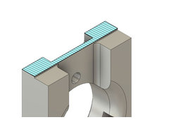
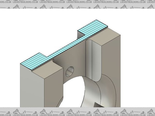
Upright1_rev1_cut
If we assume that we can load this to a stress level of 150 MPa then that is 150 N/mm2: 1560x150 = 234 000 N
234 kN divided by 9,81 equals 23853 kg and that is equal to a fairly large excavator
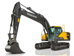
EC220
That is in pure tensile load and should not be used as a design figure by any means!
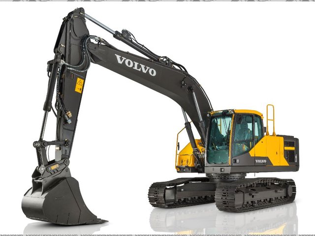
Just doing a small correction for shear and using von Mises gives a factor of 0,577 = 13763 kg which is a much smaller excavator
Take all this with a grain of salt, its just me playing with some numbers.
Grimsdale - 2/7/19 at 07:38 AM
quote:
Originally posted by coyoteboy
6082 does have a huge specific strength penalty though, I guess it depends on whether a race vehicle will see significant corrosive environment. And
whether he plans to heat treat after machining or before?
SCC isn't in my day to day, I'd be interested to see some of the automotive failures if you have any links to study?
A corrosive environment to me is any contact with water. If it's an f1 car that's going to live in air conditioned luxury with only
occasional wet uses before the part is replaced, it will of course be fine. Stored in a garage with a little condensation for years would be less
ideal.
It's a shame it's much stronger in comparison, but I don't see 7075/any copper containing Al alloy to be an option.
Heat treatment before or after machining might affect residual stresses (which can drive SCC on their own).
I don't have any examples i can share in any detail. I have seen similar examples of corrosion based failures of aluminium alloys in aircraft
seat rails (which generally live in a dry environment, apart from occasional cleaning and spilt drinks), cheaply manufactured lorry wheels etc.
quote:
Originally posted by mi2jaca
I will have to look into the material selection and SCC. Can proper surface treatment help? Anodizing?
I've just completed a failure investigation of a 7075 component that was anodised. Whilst the anodised layer isolates the aluminium from the
environment initially, you are totally reliant upon the layer staying intact. It will certainly slow the rate of failure, but any minor damage such as
a stone chip, or even from tightening a nut against the material will cause small defects, which allow moisture to penetrate and initiate
corrosion.
Here is an image of a cross section through the failed component showing SCC initiation from defects in the anodised layer, approx 25x magnification.
The component did not appear visually to be excessively corroded, although there were some white whisps of corrosion product on the surface.

[Edited on 2/7/19 by Grimsdale]
JAG - 2/7/19 at 10:06 AM
5 Million cycles is just vertical loading of the Knuckle - suspension movement up or down. Other types of loading have different profiles and total
counts.
There are lots of other load cases (Steering inputs, Cornering forces, Kerb strike force and Pothole impact etc...) that we consider. We have a huge
list of 'load cases' and the actual loads vary as they're almost all driven by the vehicle weight and tyre/damper/spring tune.
We calculate the loading to enable parts to be designed and manufactured. Once we've built some prototype cars we collect actual
'road-load' data to compare and confirm our designs are safe or revise them to make them safe.
I imagine that this design is going to be validated more by very rough calculation and then empirical testing.
Mr Whippy - 3/7/19 at 07:00 AM
as before, just use something tried and tested from a production car, you will have zero risk of failure
mi2jaca - 3/7/19 at 09:04 AM
quote:
Originally posted by Mr Whippy
as before, just use something tried and tested from a production car, you will have zero risk of failure
As before, that was not part of the question. Nothing for you to see here, please move on
Mr Whippy - 3/7/19 at 09:53 AM
quote:
Originally posted by mi2jaca
quote:
Originally posted by Mr Whippy
as before, just use something tried and tested from a production car, you will have zero risk of failure
As before, that was not part of the question. Nothing for you to see here, please move on
 LOL what an attitude
mi2jaca - 3/7/19 at 10:19 AM
quote:
Originally posted by Mr Whippy
quote:
Originally posted by mi2jaca
quote:
Originally posted by Mr Whippy
as before, just use something tried and tested from a production car, you will have zero risk of failure
As before, that was not part of the question. Nothing for you to see here, please move on
LOL what an attitude
Sorry, not trying to have an attitude. Sorry if I came out a little too harsh.
I have been looking at production car components but I just can’t seem to get the geometry that I want.
Once again sorry, I’m not trying to be a prick.
mi2jaca - 3/7/19 at 10:59 AM
To get back on the subject I think I will have to go with a 6xxx series material instead, I will see what I can get my hands on.
In my latest revision you might have noticed that I added a second hole for the lower ball joint to make for some caster on either side of the car.
I am also wondering if I could/should use these uprights on all four corners. With different brackets (there we go again!) that would be a
possibility. Maybe I am just over-engineering things now?
coyoteboy - 3/7/19 at 08:59 PM
quote:
Originally posted by Mr Whippy
LOL what an attitude
To be fair, I was thinking the same as him - he's already stated multiple times that he doesn't want to, drop it
Camber Dave - 4/7/19 at 07:36 AM
I've been following this thread with interest.
You did ask for a critique but personally I found some comment unhelpful despite the highly qualified authors.
I would narrow the lower ball joint area to give more room for the lower arm, caliper mounting and rim clearance ect.
Your design (also as used on the Elise) permits 'in paddock' camber change without causing toe/tracking change.
Ideal for optimising Tyre temperatures.
For a project I speculated about using a Water jet cut blank similar to the Elise alloy ones. It would have had a double row ball bearing retained by
a bolted ring that also formed the caliper mount (Using a radial bolt caliper).
quote
"I am also wondering if I could/should use these uprights on all four corners. With different brackets (there we go again!) that would be a
possibility."
From the first instance I thought this was an obvious application. For the rear turn the item upside down and replace the steering arm with a
'Dogbone ' bracket to take 2 rod ends from the lower arm.
There was a design shown at Stoneleigh show in 2006 that used exactly what you are thinking of.
A google search failed to find more info but U to U me with your email so I can send you my pics
mi2jaca - 18/7/19 at 06:16 PM
Still tinkering along with this project. I have modelled a possible brake disc and realised that I only have 3 mm clearance between disc and upright.
Could this be a problem? I suppose I will use a shield of some sort on the inside of the brake disc so maybe it isn’t a problem regarding sticks and
stones getting in there?
Upright2_rev0_20190718
I also humoured myself with using Shape Generator in Autodesk Inventor
(https://knowledge.autodesk.com/support/inventor/learn-explore/caas/CloudHelp/cloudhelp/2018/ENU/Inventor-Help/files/GUID-D74F47F3-FE22-44EF-85BE-7C6B
1F56DCF9-htm.html) to see what it could come up with. Would you trust these uprights?
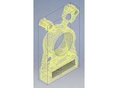
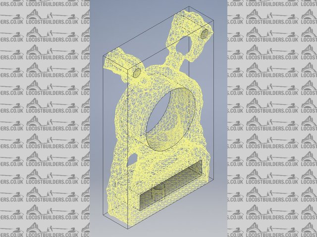
Upright Shape Generator
coyoteboy - 18/7/19 at 09:10 PM
https://pdfs.semanticscholar.org/15e1/6bc007369b4e1933a000daa0226652197e45.pdf
3mm wouldnt bother me at all.
Is that a student license or a subscription you're using for shape gen. I've fancied using shape gen for fusion 360 but the price is vast.
Another route to the same answer is doing it manually - start with a block of metal with rigid entities at faces you need, clearance where you need,
load it, mesh it, solve it, then use the FoS clipping to refine a bit. We do this a lot when we need to really pare down mass.
[Edited on 19/7/19 by coyoteboy]
mi2jaca - 19/7/19 at 02:46 PM
quote:
Originally posted by coyoteboy
https://pdfs.semanticscholar.org/15e1/6bc007369b4e1933a000daa0226652197e45.pdf
3mm wouldnt bother me at all.
Is that a student license or a subscription you're using for shape gen. I've fancied using shape gen for fusion 360 but the price is vast.
Another route to the same answer is doing it manually - start with a block of metal with rigid entities at faces you need, clearance where you need,
load it, mesh it, solve it, then use the FoS clipping to refine a bit. We do this a lot when we need to really pare down mass.
[Edited on 19/7/19 by coyoteboy]
Thanks for the link! I see that they are using 7075-T6, they are not concerned about SCC? From other FSAE papers I have seen that 7075 seems to be the
preferred material but I guess their life-span calculations are rather on the short side.
We have a subscription for Autodesk Inventor at work that I have free access to but we never use the Shape Generator so I am just playing around with
it. Your way of doing it manually sounds like a far better solution for most cases.
coyoteboy - 19/7/19 at 04:36 PM
Yeah 7075 isn't a problem for a race car, and I'm not aware of SCC being brought up in the design judging, but because the brief is a low
cost, short run race - only car, many areas are neglected if they are not immediate failure risks. Tends to yield fun innovations.
https://images.app.goo.gl/ipnJy3XEoBagVZip8
mi2jaca - 6/8/20 at 04:04 PM
I am resurrecting this thread, much to the amusement of Mr Whippy I hope
Life gets in the way, tumors and stuff, you know the drill - but I haven’t given up on this idea, at least not as an exercise for the mind.
Actually I managed to get a prototype 3D-printed so that I could make a test fit of the hub and other details but of course I ran into trouble
directly, Doh!

Will have to make adjustments and maybe trim down the size somewhat. It’s always one thing to see things on the screen and another in real life

steve m - 6/8/20 at 05:31 PM
My comments will seem a tad harsh, but along with Mr Whippy, and a couple of others, Re inventing the wheel is not the way forward
Its taken you 14 months from design to a pre production plastic item, that as you say, doesn't quite fit, and that is about 0.001 % of a
completed car, especially if you plan on re inventing the wheel with every part "that you feel does not work" your car will never roll out
of the garage, as fossil fuel will of all been used
There is a lot of joy in building a car from scratch, and I have done it, so know the drill, mine took two years, from start to on the road. others
have done it in 6 months, some on this site started building in 1999 and still havnt finished and never will!!
Building a car from scratch has its own dilemma's to deal with on the way, and some serious head scratching moments, along the way, but re
inventing the wheel on some serious critical components, like uprights, Imho unless you have some form of very high standard in metal science and
engineering, please leave it to the professionals who have since the first car ever drove, enhanced the components to an incredibly safe area
As said, just my humble opinion, and its your build, car and life
steve
[Edited on 6/8/20 by steve m]
[Edited on 6/8/20 by steve m]
Theshed - 7/8/20 at 11:49 AM
I respectfully disagree with you Steve.
I have been building my car for 18 years and it has given me a huge amount of pleasure. I make just about everything myself including my bolts. Along
the way I have learned so much. The journey is as important as the destination for me (although sanding down GRP is wearing a bit thin). Perhaps the
OP feels the same way. It is a matter of choice really.
The design of these uprights looks perfectly conventional and IMHO preferable to those lethal looking mushroom inserrts that some uprights use.
I have bolt on brackets on my uprights as do many endurance cars. Of course stress points and corrocion need to be addressed but that is no big deal.
When you look at the horrendous welding in the picture gallerys in this site it puts worrries about a thick upright cracking into perspective.
HowardB - 7/8/20 at 12:01 PM
quote:
Originally posted by Theshed
(although sanding down GRP is wearing a bit thin).
SJ - 7/8/20 at 12:33 PM
quote:
quote:
Originally posted by Theshed
(although sanding down GRP is wearing a bit thin).
Just done exactly that on my boat and got a hole as a result
mi2jaca - 10/8/20 at 10:19 AM
@steve m No problem! Thanks for the input.
I am however not building a car at the moment, just designing an upright and that was what I was looking for input on. I realize that with my current
rate of progress it would take me several hundred years to build a complete car. But I think that I will complete the rebuild of my motorcycle and
maybe the scratch build of a single cylinder engine before I dig into the car project for real
I have a rule against too many projects at once that I try to keep. Barely…
@Threshed That is a completely opposite view as you say and maybe takes us into a bigger discussion about project management(?) maybe, progress and
the question of when to build and when to walk away. How much energy do you want to invest in a project? For me it is as much (if not more) the
journey as the end result that counts.
I know that I read a great discussion on the subject a while ago but can’t remember where it was. Will see if my memory comes back to me later
maybe.
Cheers for the input again but at the moment I think I will just clench my fist in my pocket and not post more here for the time being.
Best regards,
Mr Whippy - 10/8/20 at 01:38 PM
The interesting thing I take from this thread is the reality that designing a car completely from scratch is really really complicated and easy to
underestimate the shear amount of engineering and material science that has went into every single part of even the most humble production car.
MikeR - 10/8/20 at 01:59 PM
On a tangent, if you're not racing it, you'll need something to cover the wheels to go on the road / normal track days. These often mount
from the hub at the front.


