owelly
|
| posted on 16/7/12 at 09:06 PM |

|
|
Electronic help needed!
This should be an easy one for those who do such things....
I'm currently trying to gather the bits together to fit an Electric Power Steering column off a Vauxhall Agila/Suzuki Wagon R to my kit. To get
the speed sensitive bit to work, the EPAS ECU needs to see a pulsed signal ov 0-1v and 9-12v. I'm fitting an electronic sender to my type 9 but
it gives a pulsed 0v to 5v. Will 5v be enough to satisfy the EPAS ECU or will it want the whole 9v+? What gizmo can I use to step the pulse from 5v to
over 9?
Cheers chaps and chappesses.
http://www.ppcmag.co.uk
|
|
|
|
|
MikeRJ
|
| posted on 16/7/12 at 09:27 PM |
|
|
Before you even get to the signal level (which is fairly easy to correct), are you sure the pulse frequency (i.e. pulses per mile) of the Ford sender
is remotely similar to that used in the Vauxhall?
|
|
|
AdrianH
|
| posted on 16/7/12 at 09:30 PM |
|
|
I would say a single transistor stage should do it, something like the typical BC108 4K7 from your 0 to 5 Volt signal to the base of the transistor
put a 4K7 from the collector to 12 volt and take off at the collector to the steering input.
Base current around 1 mA
Collector current around 3 mA but depends on what the steering input requires?
The Emitter grounded.
The single transistor will invert the signals in that 5 Volt will become 0 Volt and 0 volts in will become 12 Volt or 13.8 Volts depending.
I would also add a few 1nF caps around to provide a bit of filtering of spikes.
Do you know if there is a maximum input to the steering controller or not?
Last point is the output from the type 9 sensor actually 0 to 5 volt Square or is it a sine wave output?
Edit for small change.
Adrian
[Edited on 16-7-12 by AdrianH]
Why do I have to make the tools to finish the job? More time then money.
|
|
|
britishtrident
|
| posted on 16/7/12 at 09:41 PM |
|
|
quote:
Originally posted by owelly
This should be an easy one for those who do such things....
I'm currently trying to gather the bits together to fit an Electric Power Steering column off a Vauxhall Agila/Suzuki Wagon R to my kit. To get
the speed sensitive bit to work, the EPAS ECU needs to see a pulsed signal ov 0-1v and 9-12v. I'm fitting an electronic sender to my type 9 but
it gives a pulsed 0v to 5v. Will 5v be enough to satisfy the EPAS ECU or will it want the whole 9v+? What gizmo can I use to step the pulse from 5v to
over 9?
Cheers chaps and chappesses.
Are you sure requiring 2 pulsed speed inputs seems strange
The 9 to 12v sounds more like the DC power supply requirements than an input signal. ?
The 0 -1 v sounds the raw output from a normal V-R ABS wheel speed sensor easy enough to wire up if you are using Sierra bits in the suspension.
[I] What use our work, Bennet, if we cannot care for those we love? .
― From BBC TV/Amazon's Ripper Street.
[/I]
|
|
|
AdrianH
|
| posted on 16/7/12 at 09:43 PM |
|
|
I read that as 0 to 1 Volt was low input and 9 to 12 Volt high level input!
3 to 9 volts a bit indeterminate as in logic levels. I am correct in this or as above two inputs needed?
Adrian
Why do I have to make the tools to finish the job? More time then money.
|
|
|
owelly
|
| posted on 16/7/12 at 09:58 PM |
|
|
Here, have a looksy at these numbers for the EPAS ECU...
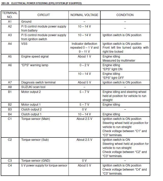
I read it as the speed signal is pulsed from below 1v to over 9v. Not two separate inputs.
I have no idea if the Ford and Suzuki (don't go confusing things as the Vauxhall corsa stuff uses a completely different system!) use the same
pulses per revolution. I was just going to try it and see what happens! I know the Ford sender pulses 8 times per revolution, as measured with my
multi-meter. I can soon find out how many revolutions occur per revolution of the propshaft. I just need to find a willing Wagon R to try the same
stunt.
I'll busking most of this to make use of the column I have without resorting to using it with the manaully variable, but non-speed sensitive
system that other folks are using.
Thanks for the help so far.
ETA the VSS is the vehicle speed sensor...
[Edited on 16/7/12 by owelly]
http://www.ppcmag.co.uk
|
|
|
BenB
|
| posted on 16/7/12 at 10:03 PM |
|
|
To convert a 5v high signal into a 12v high signal I would use a single rail comparator fed the signal into one arm and 3v into the other and run on
9v. Simples. As long as it's square wave. Otherwise you'ld need an op-amp in multiplier mode.
|
|
|
AdrianH
|
| posted on 16/7/12 at 10:30 PM |
|
|
Few more bits simple fag packet style
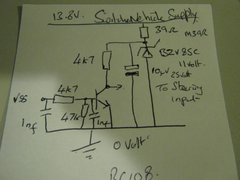 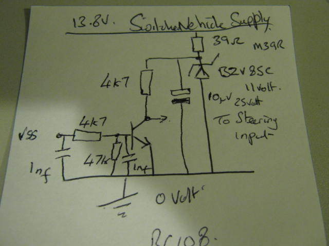
fag packet style
Probably a couple of £'s parts from Maplin.
Get 250mW resisters apart from the 39 Ohm which is 0.6 watt.
The Zener is 1.3 Watt.
Electrolytic Cap typical 10uF 25 Volt working.
BC108.
there is a few depends, like the VSS must go below 0.6 Volt and go up to 5 Volt square wave. The current in the steering input must be negligable,
(the 4K7 collecotr load can always be reduced a bit.
Sort of thing I might knock up as a will it work type of thing.
Yes a voltage comparator with a pot on the level trigger would be better, I will see if there are any simple kits or ready made boards.
Adrian
Why do I have to make the tools to finish the job? More time then money.
|
|
|
owelly
|
| posted on 16/7/12 at 10:40 PM |
|
|
Excellent reply! Many thanks. I can just about manage to blob solder onto a board so I may have a trip to Maplins this week.
http://www.ppcmag.co.uk
|
|
|
loggyboy
|
| posted on 16/7/12 at 10:50 PM |
|
|
Might be easier in the long run?
Corsa B C - Electric power steering controller box - With ECU plug - EPAS RALLY | eBay
Mistral Motorsport
|
|
|
owelly
|
| posted on 16/7/12 at 10:50 PM |
|
|
Would there ba an easy way to convert the pulses per rev from the sensor? Just in case the signal from the Ford do-hickey tells the ECU the
car's doing 120mph at walking pace?
http://www.ppcmag.co.uk
|
|
|
owelly
|
| posted on 16/7/12 at 10:54 PM |
|
|
quote:
Might be easier in the long run?Corsa B C - Electric power steering controller box - With ECU plug - EPAS RALLY | eBay
But that controller is for the Corsa which is totally different to the Agila and it removes the speed sensitive feature which is what I'm trying
to keep!
The Agila/WagonR column is smaller, lighter, has an electro-clutch etc, whixh is why I want to use it.
http://www.ppcmag.co.uk
|
|
|
AdrianH
|
| posted on 16/7/12 at 11:04 PM |
|
|
I have also found a voltage comparator style circuit using an op amp at Maplins.
it would need a bit of a change but could give a variable switching point. It is their Thermostat kit.
A Velleman kit circuit found here http://www.velleman.eu/downloads/0/minikits/manuals/manual_mk138.pdf
Maplins part number RR51F.
Changes would be to remove C3 and put a couple of nF cap in instead.
Do not go between the NTC pins but input across R4 Would still like to see a resister in line. No relay use a 470 Ohm 0.6 Watt resister instead and
still go out from the collector. The two diodes and 1K resister also removed.
Adrian
To alter the number of pulses would need a sort of counter circuit.
I have to ask but is this needed on the kit, I have thought about adding one when doing the Autosolos, but found I can cope quite well.
Taking me 3 edit's to say what I mean, bed time for me.
[Edited on 16-7-12 by AdrianH]
Why do I have to make the tools to finish the job? More time then money.
|
|
|
owelly
|
| posted on 16/7/12 at 11:16 PM |
|
|
Thanks again. You've lost me a bit with your explanation but I'll figure it out after a bit of sleep!
My car has very heavy steering. The quick rack doesn't help. I can improve it by pumping up the front tyres but then it just understeers. So I
run the fronts at 16psi. I'm keen to keep the speed sensitive bit to keep some feel at higher speeds.
Rallywiz have started making a controller kit for the Agila EPAS but, again, you lose the speed sensitive bit.
ETA. Here's a clip of my chum hustling the car round some cones. It takes two hands to turn the wheel with such effort, that the stitches have
pulled out of the steering wheel!
http://m.youtube.com/watch?v=zIO9G388sRo
[Edited on 16/7/12 by owelly]
http://www.ppcmag.co.uk
|
|
|
snapper
|
| posted on 16/7/12 at 11:45 PM |
|
|
And this site for Corsa and others
Rally wiz
I eat to survive
I drink to forget
I breath to pi55 my ex wife off (and now my ex partner)
|
|
|
MikeRJ
|
| posted on 17/7/12 at 07:22 AM |
|
|
quote:
Originally posted by owelly
Would there ba an easy way to convert the pulses per rev from the sensor? Just in case the signal from the Ford do-hickey tells the ECU the
car's doing 120mph at walking pace?
You would need to use a "Speedo Healer". This is a function that is not particularly easy to DIY, unless you only need a binary division
(divide by 2,4,8 etc.). For any other divider (including fractional) a microcontroller would be the simplest solution.
Note also that a single transistor level shifter will also invert the VSS signal. Probably not an issue unless it produces very narrow pulses rather
than a square wave, in which case the duty cycle would also be inverted.
[Edited on 17/7/12 by MikeRJ]
|
|
|
owelly
|
| posted on 17/7/12 at 07:41 AM |
|
|
Snapper, see post above yours. I'm trying to keep the speed sensitive bit....
I think I'll just do the 5v to 12v thing first and see how far away the calibration is. I'm guessing that at a standstill, there will be
maximum assistance which gets less as the road speed increases. That works for slow speed manouvering so it'll do for a start!
Cheers again guys.
http://www.ppcmag.co.uk
|
|
|
owelly
|
| posted on 17/7/12 at 08:25 AM |
|
|
A bit more digging suggests that Ford electronic speedo drives are 8 pluses per revolution which aims to be 8000 revs per mile. I can soon confirm
that once I get the speedo sender in my Type 9. I just need to find out what the WagonR speedo uses.
http://www.ppcmag.co.uk
|
|
|
britishtrident
|
| posted on 17/7/12 at 09:17 AM |
|
|
Most VSS signals are straight from the wheel speed sensor typically using 24 to 32 teeth 0 to 1v about 20,000 to 40,000 pulses per mile
[I] What use our work, Bennet, if we cannot care for those we love? .
― From BBC TV/Amazon's Ripper Street.
[/I]
|
|
|
owelly
|
| posted on 17/7/12 at 09:21 AM |
|
|
But the VSS on the Agila/Wagon R is on the gearbox and appears to be a two wire jobby that simply grounds the output from the ECU.
It looks like I'll have to buy a Wagon R to find out......
ETA, the VSS is a three wire unit, not two. It has a 12v supply, a wire through the loom to ground and the signal wire to the EPAS ECU.
[Edited on 18/7/12 by owelly]
http://www.ppcmag.co.uk
|
|
|
owelly
|
| posted on 17/7/12 at 09:26 AM |
|
|
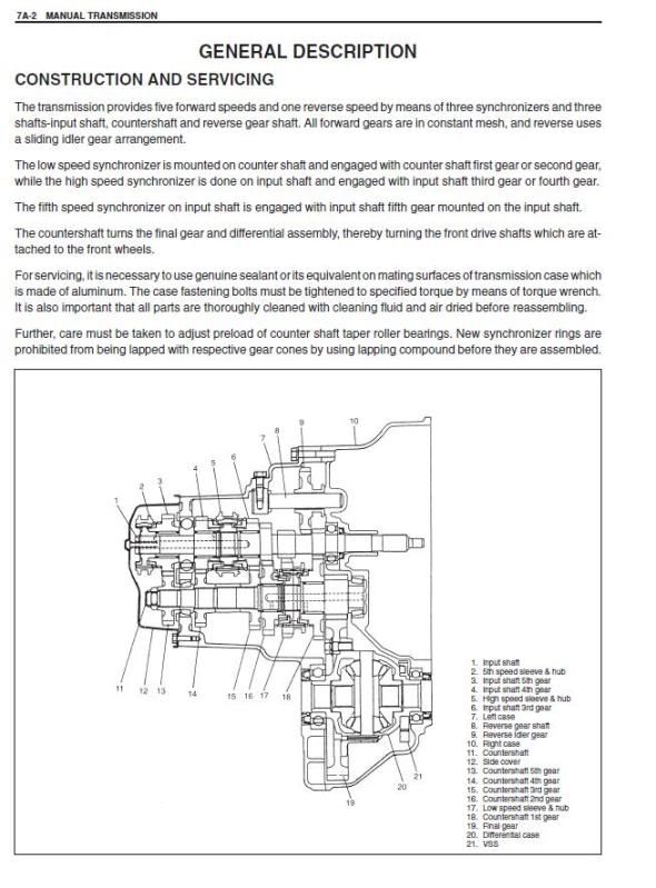
VSS in gearbox, thus....
http://www.ppcmag.co.uk
|
|
|
owelly
|
| posted on 17/7/12 at 01:50 PM |
|
|
I have found a list from an American company that supplies aftermarket cruise control systems, that gives pulses per mile. It suggests that almost all
Fords use 8000 pulses/mile and that Vauxhall/Suzuki use 4000pulses/mile.
I'll see how my set-up is looking with my 13" wheels and 3.62:1 diff!
http://www.ppcmag.co.uk
|
|
|
froggy
|
| posted on 17/7/12 at 03:35 PM |
|
|
if its a two wire sensor on the box then it will need to be converted to a digital signal either through the speedo head like saab/gm systems or in
the ecu itself with a converter . check the agila wiring diagram to see if the vss signal goes to the clocks or direct to the ecu 
[IMG]http://i144.photobucket.com/albums/r187/froggy_0[IMG]
|
|
|
owelly
|
| posted on 17/7/12 at 05:11 PM |
|
|
It goes direct to the EPAS ECU by what I can tell by the wiring diagram.
http://www.ppcmag.co.uk
|
|
|