
Camber adjuster failier on Haynes Roadster warning
ashg - 17/3/10 at 06:43 PM
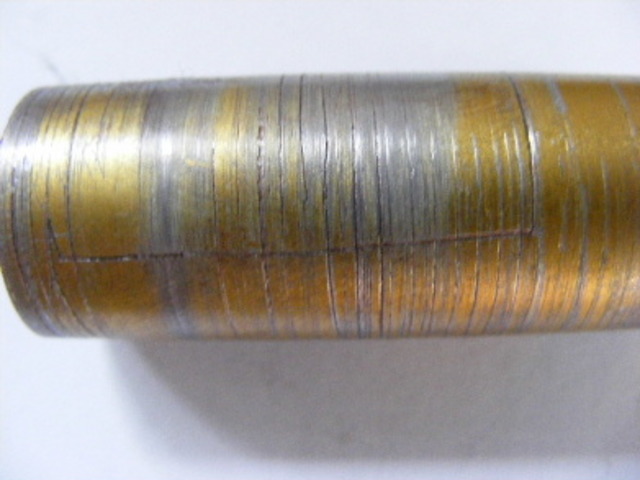
Had a rather nasty failure on the car today. The one of the quick camber adjusters on the front suspension decided to catastrophically fail and allow
the top wishbone to detach from the hub.
My friend chris was driving at the time luckily he noticed that it had failed and stopped before the front wheel parted company with the car.
i would seriously advise you to think about changing them for stronger items if they are on your car or revert back to a design with the fixed
threaded tube.
this is the adjuster in question
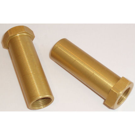
and this is the failed one.

yes your not seeing things the bolt head as completely come off
jacko - 17/3/10 at 06:48 PM
I have always thought they looked cr++
Paul (Notts) - 17/3/10 at 06:49 PM
Did the thread from the top TRE go all the way through the adjuster as it does on a normal wish bone and have a lock nut on It?
where are they from ?
Paul
ps lucky to be still with us.!!!
turbodisplay - 17/3/10 at 06:51 PM
Is that ali or steel?
The sharp transition of shape arround the head is a stress raiser, if it has a rounded transistion the stress will be less.
Darren
rayward - 17/3/10 at 06:51 PM
what material are they made from ??
doesn; look much thickness left after machining
Ray
Neville Jones - 17/3/10 at 06:51 PM
Is that part made from ali?
If so, extremely poor material choice by the designer/seller.
Those things should be steel. No ifs, buts, or maybe's!
Cheers,
Nev.
turbodisplay - 17/3/10 at 06:58 PM
I can't believe it is ali, it looks like it due to being anodised. I`m not a material designer but i wouldn`t use ali, nor would I anodise it,
that makes it more brittle!
Darren
dogwood - 17/3/10 at 07:07 PM
You really an unlucky bu***r ain't you.
Did the rest of the day go OK though?
deanwelch - 17/3/10 at 07:18 PM
thats your luck used up for awhile
ashg - 17/3/10 at 07:19 PM
yeah day went fine should have v5 in the post at some point. well i am lucky in the way that it didnt fail at full bore down a twisty lane and kill
either me or chris.
the material is ali and the trackrod ends went all the way through with a locknut on the ball joint end as they are designed to be used.
i got them from rally design although many other shops sell them also.
britishtrident - 17/3/10 at 07:19 PM
These adjusters are just fine is used correctly with nuts at both ends.
The hex end should go to the outside backed by a half nut, the inside should have a full nyloc or other self locking nut.
TigerB6 Paul - 17/3/10 at 07:23 PM
Has anyone ever heard of one of those failing before?? I certainly havent and know that loads are in use!!
Maybe before the huge panic with everyone criticising the design and material choice, it should be considered that it could well be a one off caused
by an overtighted locknut / pothole / sharp edge on the wishbone etc etc.
Keep an eye out for sure - but seems a big over-reaction to start questioning design etc so early for what may well be a one off failure.
Glad your mate spotted the failure so quickly anyway Ash
ashg - 17/3/10 at 07:30 PM
i initially thought it could have been an overtightened locknut but i checked the other side when i got home and it was fine so have ruled it out.
the failure happened under heavy breaking in a right hand bend. the side that failed was the passengerside
carlknight1982 - 17/3/10 at 07:30 PM
any damage to the car? other than the shi*t stains on the seat?
britishtrident - 17/3/10 at 07:53 PM
quote:
Originally posted by ashg
i initially thought it could have been an overtightened locknut but i checked the other side when i got home and it was fine so have ruled it out.
the failure happened under heavy breaking in a right hand bend. the side that failed was the passengerside
Thats fairly obvious from the way it flailed the upper ball joint shank will always be subject to forces pulling it out from the wisbone.
ashg - 17/3/10 at 08:10 PM
luckily no damage to the car or the occupant, counting my blessings on that front as i would have been really upset if my mate chris had got hurt
because my car failed on him.
i have got these adjusters front and back. both the front and back upper wishbones will be replaced for non quick adjust items. i would rather spend
an hour adjusting the wishbones than die from a failure i could have prevented
[Edited on 17/3/10 by ashg]
Ben_Copeland - 17/3/10 at 08:23 PM
Ooo scary, wont be bothering with them after all !!
RichardK - 17/3/10 at 08:24 PM
I'd do that too for complete peace of mind. I do respect what BT says but there is just something in my head that says thats not the best
material for that particular item.
Cheers
Rich
t.j. - 17/3/10 at 08:29 PM
can anyone give me a picture of the (right) use off these?
rgrs - 17/3/10 at 08:37 PM
After reading the above i did a quick search and sorry to flak monkey but this was the first image i could find:
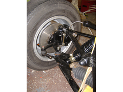
mine are fitted in the same way, comments ?
Neville Jones - 17/3/10 at 08:38 PM
quote:
Originally posted by britishtrident
These adjusters are just fine is used correctly with nuts at both ends.
The hex end should go to the outside backed by a half nut, the inside should have a full nyloc or other self locking nut.
The mix of ali and steel, in that location, could never be condoned by any half decent materials engineer, or mechanical engineer. Least of all
reasons, being the galvanic action and corrosion. The things will eventually flog out, however fitted. With the low mileages these cars do, that could
take some time. Still doesn't justify the use of ali, though.
Just damned poor engineering, or gross lack thereof.
Cheers,
Nev.
[Edited on 17/3/10 by Neville Jones]
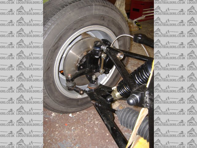
flak monkey - 17/3/10 at 08:42 PM
If you notice, the ones on my car in the pic above are steel.
I made my own as I didnt think that the aluminium ones were up to the job. Though it will depend what alloy they are made from. If they were 6063T6
then they would be more than adequate. My bet however is that they are just 1000 series.
And I should add mine have been ok for close on 7000miles now. And were recently removed for a check and are still perfect.
David
locoboy - 17/3/10 at 09:20 PM
They look very similar to the ones i bought from GTS tuning.
Dont GTS supply rally design?
Isn't Darren a poo hot suspension designer................................
a4gom - 17/3/10 at 09:30 PM
quote:
These adjusters are just fine is used correctly with nuts at both ends.
might be worth asking rally design how they should be fitted, I have mine fitted like the ones in flakmonkeys pic and as far as I know this is the way
they were intended to be used. Pretty sure you'd struggle to get a joint with a long enough length of thread to get it right through a nut, the
adjuster, the bone and still be able to put a nut on the end?
[Edited on 17/3/10 by a4gom]
Toltec - 17/3/10 at 10:15 PM
The wheel only came free of the upper wishbone as I reversed onto a drive with quite a bit of lock. The idea that it went while braking on a rhder is
a guess. The guy that pulled out on me forcing me to stop on the rab also stopped a few car lengths further on. At the time I thought he was just in
shock at realising that staring at me as he pulled out did not give him right of way. Later when the slight suspension issue became apparent I
wondered if he had stopped because a chunk of rubber covered ali had whacked into his car. I could not find the missing piece on the road so where it
actually broke??? I had just done a full lock U-turn to get to the right position to reverse and the wheel stayed in position, it only came out as I
reversed.
It did give me a bit of a shiver at the time, however in hindsight I doubt the ball joint would pull free of the wishbone very easily unless on plenty
of lock. I pulled the wheel back out to see if I could get the rod/stud back into the wishbone tube but the angles were so different there was no way
they would slide back together. I think it quite likely that the change in angle would wedge the parts together at lower lock.
It was the first time I had driven the car and it is still really in its shakedown phase so I was not leaning on it too hard fortunately. Thinking
back it did tighten line slightly on the exit to a rab, nothing dramatic though and I would otherwise just put it down to the surface angle change on
the exit.
craig1410 - 17/3/10 at 11:02 PM
quote:
Originally posted by locoboy
They look very similar to the ones i bought from GTS tuning.
Dont GTS supply rally design?
Isn't Darren a poo hot suspension designer................................
Strikingly similar to these
and these
I'd inform Rally Design if I were you because I think you did fit them as intended (wrt to BT) and they have failed due to poor design. I agree
that Ally is a bad material when connected between a steel drag link with steel locknut and steel wishbone. Rally Design should withdraw these from
sale and refund your Ł9.50. To be honest, Ł9.50 is way to cheap for something like this if it was designed properly.
Edit: If you look closely at this picture from the GTS Tuning
website you can see a camber adjuster fitted to the top wishbone. Click on the image of the car to enlarge. Looks to me like you did fit it
correctly.
All in my humble opinion of course...
Craig.
[Edited on 17/3/2010 by craig1410]
[Edited on 17/3/2010 by craig1410]
andyharding - 18/3/10 at 08:06 AM
Looks like a bad design to me, over tightening the lock nut is most likely the cause of failure but because the part is hidden you can't tell
you've damaged it until it fails. Can't believe they are made of ally.
Think I'd be bringing small claims against the supplier...
alistairolsen - 18/3/10 at 08:40 AM
I considered these, but having looked at them, they fit inside a one inch tube from memory giving an OD of about 22mm and are 18.5mm bore across the
outside of the threads leaving a 1.75mm wall thickness with a nice cut thread as a stress raiser. I wouldnt build that in steel never mind alloy.
That said I would always install them with the nut outwards and a half nut on the inside end to lock them. That way they can only fail in a relatively
safe manner.
boggle - 18/3/10 at 08:44 AM
why would you use these over a piece of threaded material welded into the top wishbone???
iank - 18/3/10 at 08:59 AM
quote:
Originally posted by boggle
why would you use these over a piece of threaded material welded into the top wishbone???
Because that would only be adjustable by a whole thread, these give infinite adjustment.
alistairolsen - 18/3/10 at 09:00 AM
because you can adjust them by a tiny amount, without removing the ball joint. With threaded bones you're restricted to a full turn of the ball
joint on asymmetric wishbones (which they will be on a book locost chassis with appropriate castor) which i s~1mm
boggle - 18/3/10 at 10:29 AM
i see......

eddie99 - 18/3/10 at 11:11 AM
As said earlier, I think this is a one off problem and maybe something else caused it. Lots of people run these adjusters on their cars and i
haven't heard of a problem before and i bet alot of them have been thrashed around a track!
Liam - 18/3/10 at 11:28 AM
HOLY POO!! This is shocking!
They could be made of chocolate if the ball joint went all the way through and there were nuts on both sides as BT describes, but looking at the
pictures this doesn't seem to be the case. In fact it's definately not the case or it couldn't have failed and come apart like that at
all!
Given that this design therefore relies entirely on the tensile strength of the adjuster to stay in one piece, it just beggars belief it's so
thin and made of anodized ally!! In fact of course it's far weaker even than the part's tensile strength when you consider
fatigue/endurance - a double whammy against choosing ally.
I take it it snapped pretty much right where the ball joint shank ended? I literally can't believe this product was sold. Wouldn't even
trust a steel one that thin personally.
Eeek!
Liam
alistairolsen - 18/3/10 at 11:35 AM
I suspect this was how it was fitted when it failed:

and IMO it should be reversed and the half nut on the inboard side but as stated earlier you would need a short housing tube or a very long track rod
end to have enough thread.
eddie99 - 18/3/10 at 11:36 AM
quote:
Originally posted by turbodisplay
I can't believe it is ali, it looks like it due to being anodised. I`m not a material designer but i wouldn`t use ali, nor would I anodise it,
that makes it more brittle!
Darren
Where did you get that from? Anodising doesn't make a material more brittle!!!
iank - 18/3/10 at 11:41 AM
quote:
Originally posted by eddie99
quote:
Originally posted by turbodisplay
I can't believe it is ali, it looks like it due to being anodised. I`m not a material designer but i wouldn`t use ali, nor would I anodise it,
that makes it more brittle!
Darren
Where did you get that from? Anodising doesn't make a material more brittle!!!
http://resources.metapress.com/pdf-preview.axd?code=mj50343764u6001m&size=largest
The anodised film is brittle and if it cracks they propagate into the base alloy.
[Edited on 18/3/10 by iank]
eddie99 - 18/3/10 at 11:44 AM
Oh ok i stand corrected. My thoughts were that yes the coating is more brittle but it doesn't affect the actual ally.
Liam - 18/3/10 at 11:50 AM
quote:
Originally posted by eddie99
quote:
Originally posted by turbodisplay
I can't believe it is ali, it looks like it due to being anodised. I`m not a material designer but i wouldn`t use ali, nor would I anodise it,
that makes it more brittle!
Darren
Where did you get that from? Anodising doesn't make a material more brittle!!!
The surface is harder and more prone to cracking, or there can be surface defects caused by the anodizing process itself. Either of these can be
nucleation points for cracks propogating further into the component, eventually leading to failure.
Edit: Darn beaten to it!
[Edited on 18/3/10 by Liam]
eddie99 - 18/3/10 at 12:05 PM
Thinking about it some more....
I actually suspect that the tube of your wishbones was too big and not the correct size for the adjuster. Therefore it would twist and could fail. But
i suspect thats the only thing. Where did you get wishbones from?
Regards
Ed
boggle - 18/3/10 at 12:20 PM
so im thinking you have to have a special top wishbone to take these, or do you have to drill out the tube???
eddie99 - 18/3/10 at 12:23 PM
quote:
Originally posted by boggle
so im thinking you have to have a special top wishbone to take these, or do you have to drill out the tube???
Maybe not a "special" one. But obviously it was designed for a certain type etc.. etc.. It's not designed for any wishbone if you get
me....
Peteff - 18/3/10 at 12:38 PM
To put a nut on both ends the track rod thread would have to be 6" long and the thread protrude both ends. They would have to be specially made
but if you could do that you would not need to buy the adjuster, just use a close fitting top tube.
craig1410 - 18/3/10 at 12:57 PM
quote:
Originally posted by eddie99
quote:
Originally posted by boggle
so im thinking you have to have a special top wishbone to take these, or do you have to drill out the tube???
Maybe not a "special" one. But obviously it was designed for a certain type etc.. etc.. It's not designed for any wishbone if you get
me....
Perhaps more importantly you would need to be sure that the inboard end of the wishbone tube had been squared off properly in a lathe to ensure that
it wasn't placing all the compression load caused by the locknut into one point.
I still say it is a bad design and when a pair only costs Ł9.50 from Rally Design you can tell that it isn't going to be aircraft spec alloy or
quality which is what I would be wanting before I would entertain such a poor design.
flak monkey - 18/3/10 at 01:04 PM
IIRC the OD of the adjuster is about 21mm (normally fitted to 2mm wall, 25mm od tube) and the thread is M18, so that gives you 1.5mm radially which
should be more than enough strength wise if the adjusters are steel or 6063T6 or similar. Yes there is a potential for fatigue and galvanic corrosion
if ali adjusters are used, but I doubt this would be a problem on our style of car due to the low milage and general dry, summer only use.
RE stress raisers - the tips of the thread are far from sharp, they will have a root radius of around 0.25mm which is enough to prevent a stress
raiser in that area. It should also be pointed out that this becomes a moot point if the adjusters are fitted correctly.
Its also worth checking the length of the adjuster. If the adjuster is too long for the tube then the assembly wouldnt be clamped tight in the wihbone
allowing some play which would cause premature failure. The adjuster should sit at least 0.75mm inside the wishbone tube.
I havent heard of any other failures, and there are a lot of these fitted to cars now and they have had a lot of track use too.
I wont be changing mine in a hurry.
[Edited on 18/3/10 by flak monkey]
iank - 18/3/10 at 01:04 PM
quote:
Originally posted by craig1410
quote:
Originally posted by eddie99
quote:
Originally posted by boggle
so im thinking you have to have a special top wishbone to take these, or do you have to drill out the tube???
Maybe not a "special" one. But obviously it was designed for a certain type etc.. etc.. It's not designed for any wishbone if you get
me....
Perhaps more importantly you would need to be sure that the inboard end of the wishbone tube had been squared off properly in a lathe to ensure that
it wasn't placing all the compression load caused by the locknut into one point.
...
Well worth checking the wishbone tube is true before fitting another - even a steel replacement.
Ideally they would be made from a steel forging.
eddie99 - 18/3/10 at 01:07 PM
Heres some figures:
OD of the camber adjuster is 22mm
Thread is 18
AREA = 502.65mmsquared
Tensile strength - 120n/mmsquared
So 6 tons
600kg car?
70% under weight at front under breaking? 210kg then per corner
Lets say the stress raiser in the corner and the thread is a factor of 6, the camber adjuster can handle 6000 kg's divide by 6 = 1000kg
add in some factor for Fatigue etc.. and still well in????
flak monkey - 18/3/10 at 01:17 PM
You need to factor in G, but your factor of 6 is more than adequate to encompass that too.
[Edited on 18/3/10 by flak monkey]
Toltec - 18/3/10 at 01:54 PM
quote:
Originally posted by eddie99
Heres some figures:
OD of the camber adjuster is 22mm
Thread is 18
AREA = 502.65mmsquared
Tensile strength - 120n/mmsquared
So 6 tons
Pi times radius squared so
Pi x 121 - pi x 81 = 125.66mmsquared
So following the rest of your calculations we get 250kg not 1000kg.
More marginal?
craig1410 - 18/3/10 at 02:25 PM
quote:
Originally posted by flak monkey
You need to factor in G, but your factor of 6 is more than adequate to encompass that too.
[Edited on 18/3/10 by flak monkey]
It's not actually that simple. You need to look at lateral loads at the contact patch which will be approximately vertical load times tyre
friction coeff. Then you will have a leverage ratio to contend with where the upright will pivot about the lower balljoint and therefore apply
compression and tension loads to the upper wishbone. You also have the upper wishbone angle to contend with although it will be less of an issue.
However, having said all that, you don't (to my knowledge) know what the breaking strain of the camber adjusters actually is or even what
material they are made from. There are also no instructions (that I know of) about which way around to fit them other than the picture I mentioned
earlier from the GTS website showing the head of the adjuster inboard which is how most people seem to fit them. And there is no information on
suitable wishbone tube sizes or torque settings for the locknut. Dynamically you need to think about maximum steady state loading and then add shock
loading factors and then a safety margin. You also need to think about fatigue effects which can significantly lower breaking strength over time.
Far too many variables to consider this in any way, shape or form and "engineered" solution.
Sorry in advance, not meaning to wind anyone up with my comments...
alistairolsen - 18/3/10 at 02:29 PM
My basic requirement was that they should not be the weakest component in the system of the top wishbone and from memory they fail at a lower
thensione than:
the pin of the balljoint in shear
the threaded section of the balljoint in tension
the two tubes of the wisbone in their component of lateral tension
the suspension mounting bolts in shear.
As all of those items are proven I don't want to add an item which is weaker.
DavidW - 18/3/10 at 02:56 PM
This does look scary but wouldn't you usually expect when driving normally that most the forces on this adjuster would be pushing inwards towards
the car i.e. pushing the steel half nut against the wishbone, not trying to pull the ali apart?
I admit I could easily be wrong....
eddie99 - 18/3/10 at 03:03 PM
Yeah its an interesting topic, and i've had a bit of fun trying to work it all out....
I think that overall everything will break eventually and mathematically it looks pretty safe, if you can show the maths to show that this isn't
the case then please do.
Talking doesn't really solve anything without the maths/figures to back up the argument in this case, otherwise its just opinions. Also the fact
that everything could be safer, and it is safe in terms of the normal job.
I personally just think that AshG was unlucky and it was a one off. If it happens again, then it'll be interesting to look into it some more.
Plenty of things break on everyday road cars but they aren't always recalled. One failure out of a couple of hundred seem to suggest that its a
one off rather than a general conceptual problem.
I could be wrong though
procomp - 18/3/10 at 03:14 PM
Hi
The thing to remeber with a lot of products that are now supplied into the kitcar market. Is was made in China for less than Ł2.
The Trouble with theses items is that they are just crap quality material. There have been some near failures where simply by tightening the lock nut
up to a suitable pressure has seen the threads pulled out. And thats before they have ever been used.
Get them made from a suitable material. And expect to pay twice what they are else where. Sure theres a guy on here who could supply if asked. Not
sure what his name is as i only ever look at his avatar.
Cheers Matt
Toltec - 18/3/10 at 03:56 PM
The cross-sectional area is about the same as that of a solid rod of 12.6mm diameter, this is similar to what a 14mm bolt would have depending on
thread pitch. Given the ball joint thread is 18mm and subject to bending and sheer as well as tension then the equivalent of a 14mm bolt to take
tension only does not sound too far out. Providing it is manufactured properly from the correct material.
The idea behind this design is probably sound, it is just the execution that could be causing the problem. As mentioned earlier ensuring the plane of
the inner rim of the tube in the suspension arm is perpendicular to the axis is going to be important. As is machining in some stress relief between
the cylinder and nut faces of the adjuster.
As also mentioned this appears to be the first instance of failure and it did not in itself cause any critical problem.
[Edited on 18/3/10 by Toltec]
Liam - 18/3/10 at 04:37 PM
quote:
Originally posted by Toltec
As also mentioned this appears to be the first instance of failure and it did not in itself cause any critical problem.
On the other hand, someone's front suspension coming apart could very easily have resulted in a fatal crash.
I'm totally with alistairolsen when he says you don't introduce a new weakest link into a proven system unless you absolutely know what
you're doing! The choice of material and surface treatment in this case indicated this 'designer' doesn't know what he's
doing. This part in ally (probably totally unknown untracable ally to touch on Procomp's comment) is the weakest link in a locost front
suspension by some considerable margin.
IMHO the fact one has failed in normal use indicates all the others out there may well be sailling very close to the wind. And in ally it's just
a matter of time anyway! Who knows how long? Certainly not the 'designer' that's for sure.
Having seen the numbers I'd retract my earlier statement about not even trusting a well made steel version, but that ally one, those dimensions,
that critical application, wouldn't touch it.
Liam
AdamR - 18/3/10 at 05:44 PM
Right... Who's up for manufacturing a batch of steel camber adjusters to identical dimensions?
I've always had my doubts about these, and the pics and discussion have me convinced I need something different. I think there'll be quite a
good market for a better version.
eddie99 - 18/3/10 at 05:45 PM
Lol not sure if David (flak monkey) could do these... He might be busy for a while if he can
boggle - 18/3/10 at 05:53 PM
just put in an order with the flak meister
ReMan - 18/3/10 at 06:15 PM
I got mine from Darren GTS, I expect he supplied them to Rally Design.
No problems yet, but as said if the prpoerly considered opinion, is that ally is not adequate, then I'd be up for a set in steel or stainless
better still as the spanner has taken the anodising off mine.
Though better still, perhaps I should commision a new set altogether with some extra caster built in?
ashg - 18/3/10 at 06:37 PM
i ordered some bar stock today. when it turns up i will be making 4 new ones in steel and upping the wall thickness by 1mm.
the tubes were perfect, i specifically turned them on the smaller precision lathe to make sure they were perfect!!

and this is the fabrication of the wishbones. as you can see there were no corners cut on my side of things

hicost blade - 18/3/10 at 07:32 PM
Does anyone know if somone could turn me up a set out of this / / /

Liam - 18/3/10 at 07:56 PM
I'd have to advise against that ^^^. The internal void defects within that material could be nucleation points for cracks to propogate from,
eventually leading to a failure. You would be better with a tougher more homogenous material such as a good Comté.
Liam
ashg - 18/3/10 at 08:34 PM
found this old thread posted up by darren at gts showing how they are meant to be used which is exactly how i did it.
here is the picture
http://www.locostbuilders.co.uk/viewthread.php?action=attachment&tid=9013&pid=87256
here is the link to the thread.
Click
so i was using it as designed.............
[Edited on 18/3/10 by ashg]
eddie99 - 18/3/10 at 08:36 PM
I've spoken to Darren today and he originally designed it about 5 years ago. Made a batch of 1000 In stronger ally stuff, he gave me all the
details and had it tested etc.. and was all good.
Rally Design when remade just remade from a given item, no drawings or anything and he doesn't know what they've made it from either...
He's going to speak to them and try and find out however.
MikeRJ - 19/3/10 at 01:02 PM
quote:
Originally posted by ashg
i ordered some bar stock today. when it turns up i will be making 4 new ones in steel and upping the wall thickness by 1mm.
I started making steel replacements for my Locost when I bought the GTS bones years ago, because it just seemed a bad idea putting a thin alloy
section under significant tensile load. Also there was a clearance problem with the hex head on my bones, the points of the hex hit the wishbone
tubes.
I'd forgotten all about them actually, I didn't have a tap to finish them and I haven't touched my poor old locost project for a long
time.
mistergrumpy - 19/3/10 at 01:17 PM
Eddies can I just verify then that if these items have ben bought from GTS they should be the stronger, tested ones? That's where mine are from
that's all.
Incidentally the nuts on my drag link are very close to the upper wishbones too but just about clear them.
eddie99 - 19/3/10 at 01:21 PM
That should be correct, When did you get them from GTS? Long time ago or very recently?
mistergrumpy - 19/3/10 at 01:46 PM
Around 2006/2007.
eddie99 - 19/3/10 at 01:49 PM
Then im pretty sure that would have been GTS own ones!
ghostrain - 20/3/10 at 12:37 PM
I rang up Rally Design and was surprised they did not know about this problem,their attitude is if ashg has a problem with the camber adjusters why
has he not contacted them directly instead of posting alarmist threads on this forum. I have the same setup on my GTS so was very worried about this
failure.
In the afternoon Darryn from GTS was just leaving, I understand that he was in discussion with Rally Design's designers about the problem.
I had a chance to discuss the problem with RD's MD,who was genuinely concerned. He advised that RD has sold 156prs of the adjusters last year and
over 50prs this year,over 4 years they must have sold over 800prs with no failures until this one. The material is HE30,type 6082 which is the same as
used by GTS,there latest supplier is an OEM who supplies Honda,ZF,TRW with ISO quality checks,they have just made another batch of 1000 camber
adjusters.
They showed me a simple test rig they had organised with Darryn where they mounted a wishbone with an adjuster and transit drag link mounted in a
vice,I was offered the opportunity to try to break the adjuster using 18" long pipe wrench. Despite using all my strength I could not break the
adjuster,a crude but impressive test I am happy to continue using the product,it certainly put my mind at rest. Their MD was surprised I could not
break the adjuster,the load I was exerting on the locknut was many times that which would be sensible in tightening that nut.
The photo shows an adjuster which appears to have ruptured in tension,we discussed it would be hard to exert high loads in that direction aside from
the load on the locknut.
The MD suggested other possible reasons for the failure and would really like to view the assembly including the wishbone and the drag link joint, it
would be a good idea if ashg were to take the assembly into Rally Design,I note his home is Rochester so it would be an easy journey,certainly help to
understand what caused this as yet one off failure.
GTS buys a lot of product from RD so it is possible that even if you bought a GTS product it could have come from RD and visa-versa.Also RD are a
wholesaler to almost every kit car manufacturer si if you bought elsewhere it could have come from Rally Design.
In the absence of sight of ashg set up the MD suggested the following possible causes of failure.
1. Too big an internal diameter in the wishbone tube,this would allow the adjuster to float inside the tube and cause a wear problem on the
adjuster.
2.Locknut loose,same effect as above.
3.Rough finish on inside of tube,same effect as above.
4.Tube inner not radiused or chamfered causing the tube edge to cut into the adjuster.
5.Tube not long enough to support the shank of the adjuster.
6.Locknut considerably overtightened,this we felt the most likely cause but after viewing the test it would have to be seriously loaded to cause
failure.
Rally Design's MD was so angry over this forum I can only repeat his words...'every kit car buider thinks he is an engineer but if you had
to answer some of the most basic questions that are asked by some kit car buiders I wouldn't trust them to build a kid's go cart, he is very
respectful of the depth of engineering knowledge of some and also respectful of those who are willing to learn,the dangerous ones are those who have
convinced themselves that they are engineers,convinced others that they know what they are talking about but actually know nothing, unfortunately
there are lots of the latter on these forums'...his words not mine,don't shoot the messenger!
I have some photos of the test which I will upload next week.
I have to say that I personally am most impressed by Rally Design,they have been so helpful in my build and their good stocks mean I am lucky they are
on my doorstep.
They were very worried about this failure and would produce a batch in steel if we ask for it but the test said for me it is not necessary,however I
would like to know why ashg adjuster failed.
eddie99 - 20/3/10 at 12:41 PM
I had also been informed of this test they did.... And think that RD were going to put a post up here explaining it all. Not sure if this is still the
case..
MikeRJ - 20/3/10 at 12:58 PM
quote:
Originally posted by ghostrain
They showed me a simple test rig they had organised with Darryn where they mounted a wishbone with an adjuster and transit drag link mounted in a
vice,I was offered the opportunity to try to break the adjuster using 18" long pipe wrench. Despite using all my strength I could not break the
adjuster,a crude but impressive test
That gives you some idea of ultimate strength, but it does not replicate the fatigue cycles which are nearly always the cause of failure of stressed
light alloy parts...
I agree with your opinion of Rally Design however, they are always extremely helpful and I've received nothing but good service from them.
However I do think that if they have a problem with this thread they should either make a post themselves, or at least contact the forum owner or
moderators rather than going through a third party.
ashg - 20/3/10 at 02:21 PM
i havent had chance to go down to rally designs as i work all week in the complete opposite direction. i did invite darren to come and have a look
when he felt like it. i would much rather it be a one off failure but at the end of the day its a failure none the less.
once the car is back on the road I will let rally design have the broken part to further their investigation. I don't want to point any fingers
as it could just be that the design wasn't suitable for my application. the haynes wishbones are a different geometry to the gts bones so there
could be a hidden issue there.
the purpose of this thread wasn't to start a man hunt on the manufacture it was to warn people to check their adjusters.
as said rally desgn have sold a lot of these adjusters and this is the first one to fail. its not constructive to point fingers and try and blame
people. if i did something wrong then fine as hopefully it will educate people how to do it correctly. if the design has a flaw then im sure the
supplier will look into correcting it.
at the end of the day nobody got hurt and that's all that matters
eddie99 - 20/3/10 at 04:17 PM
quote:
Originally posted by MikeRJ
quote:
Originally posted by ghostrain
They showed me a simple test rig they had organised with Darryn where they mounted a wishbone with an adjuster and transit drag link mounted in a
vice,I was offered the opportunity to try to break the adjuster using 18" long pipe wrench. Despite using all my strength I could not break the
adjuster,a crude but impressive test
That gives you some idea of ultimate strength, but it does not replicate the fatigue cycles which are nearly always the cause of failure of stressed
light alloy parts...
I agree with your opinion of Rally Design however, they are always extremely helpful and I've received nothing but good service from them.
However I do think that if they have a problem with this thread they should either make a post themselves, or at least contact the forum owner or
moderators rather than going through a third party.
Hang on a second, Fatigue doesn't affect materials which are under constant pressure does it?
ashg - 20/3/10 at 05:08 PM
it will if the pressure changes which is a given. but we are talking about tension here. i think the best solution is that i get the broken part back
to rally design and they can let the manufacturer's engineers have a look at it under a microscope to see what happened.
6082 properties indicate that its stretch capability isnt as good as steel but should still be fine.
the ultimate tensile strength of 6083 aly is 310MPa where as an 1018cd steel is around the 485MPa mark.
looking at the sums in matlab its looking like the ali should be strong enough which is why my broken one needs to be looked at.
have never claimed to be a materials engineer but have a good interest and work in an area of industry that considers these things daily (do a search
on Linac and you will see what i mean).
i for one like an open debate but if it starts to get out of hand i will delete the whole thread. Pointing fingers is a useless exercise, rarely
achieves anything and just doesn't interest me. look at the politics of this country!! most of our MP's are uneducated fools that spend all
day finger pointing do we want to be like them?
[Edited on 20/3/10 by ashg]
ghostrain - 20/3/10 at 06:20 PM
ashg...you started your thread with words like catastrophically failure and lucky you and Chris are to be alive and are now surprised that many others
are very worried about this failure.
I suspect that the majority of 7 style kit cars built in the last 5 years are using this design of top wishbone/drag link. You surely cannot be
surprised of the reaction to your posting.
Given your knowledge of the materials industry and the design of your front suspension why do you think your adjuster failed?
I tell you that the guys at Rally Design were very worried about your failure,their engineers in conjunction with Darryn from GTS spent most of the
afternoon trying to simulate what caused this failure without any firm conclusions.I was given very open access to their test and conversations,they
hid nothing.
The good thing,so far,to come out of this discussion is that your failure appears a one off and also no harm to you.
MikeRJ - 20/3/10 at 07:57 PM
quote:
Originally posted by eddie99
Hang on a second, Fatigue doesn't affect materials which are under constant pressure does it?
Err...that's what I said (in the opposite sense).
Toltec - 20/3/10 at 09:07 PM
quote:
Originally posted by ghostrain
ashg...you started your thread with words like catastrophically failure and lucky you and Chris are to be alive and are now surprised that many others
are very worried about this failure.
I think he was feeling pretty bad that I was driving the car when it happened and it could have been very serious.
The failure of the component was catastrophic in the sense that its function was totally impaired not in the sense it caused a catastrophe. As to why
it happened? A defect in the material maybe? Someone has already mentioned the possibility that the anodising could make the chance of cracking
higher. It failed at the end of the ball joint thread not at the hex head.
We have just had a long chat and come up with an idea of how to use these adjusters in a way that prevent the possibility of this kind of failure.
Ash is going to draw up the modification and see if it still makes sense. I might suggest he runs it past RD/Darren to see what they think.
ashg - 20/3/10 at 09:23 PM
have been thinking about it and it could actually be the design of the haynes wishbone that caused it. the tube that the adjuster sits in is actually
angled upwards at 8 degrees from the wishbone, im wondering if this could have caused the problem as it would move the stress points on the
adjuster.
either way i have revised the design of my tube that the adjuster sits in. i have now put a recess inside the locknut end so even if the adjuster
failed a second time it couldn't pull out.
here are some pictures of my new design.


arriba - 21/3/10 at 08:03 PM
Having had a chance to read through this thread and consider all the submissions I think a possible cause of failure is as follows.
The transit drag link joint does not have a limitless range of travel,without site of the manufacturers drawings I estimate it is in the range of
plus/minus 20 deg.
Ashg has stated that the joint is installed on his roadster at 8 deg to the norm. If this is using up the range of movement on bump it is possible
that at extreme bump the joint is locking out. The upright would exert a moment effect on the drag link threaded stem,the extreme of the load being at
the inboard end of the thread,exactly where the failure occured. The effect of such a hammering would be greater if the adjuster where held only
loosely in the housing tube,our current potholed roads giving greater opportunities for this hammering action. I use the word hammering for clarity
because the upright could be considered the handle of the hammer and the drag link stem the head.
A simple check to verify this theory would be to remove the spring/shocker assembly and rotate the suspension unloaded,it should be obvious if the
suspension is exceeding it's normal range of rotation.
Such a lock out is not rare-I was previously involved in the supply of high quality 5/8 x 5/8 chrome moly rod ends to a well known race car builder.
The designer used the rod end directly in place of where the drag link joint is used. On the first the loaded rod end failed in the first corner,the
designer had underestimated the range of movement of the suspension and had exceeded the angle of misalignment of the rod end,we cured the problem by
using high angle rod ends.
The massive 18mm stem on the transit drag link is unlikely to fail but if lock out is occuring then it is inevitable that the metal to metal contact
will cause some failure in the system
Rally Design
ashg - 21/3/10 at 08:19 PM
it could be possible but the 8degree angle is to improve the range of motion. the 8degree is there to make sure the ball joint is central.
its a shame that chris gibbs has been banned from here as he was involved in the suspension design. im sure he could add some interesting points to
the conversation.
arriba - 21/3/10 at 08:56 PM
I have a lot of respect for Chris Gibbs,I am sure he has calcualated the range of movement,but the range of movement on droop is not so critical,in a
vertical mode it only has to support the unsprung weight of the vehicle,it is the bump that is the critical range and load.
Having said that it is likely that it is a combination of factors that led to this failure but with one primary catalyst.
I noticed that you intend to manufacture new steel adjusters with 1 mm additional diameter,how were you intending to machine out the wishbone tubes to
accept the larger diameter. You would need a gap bed lathe to mount the welded wishbones or alternatively an adjustable reamer,which is rare and
expensive,they would be difficult to hold in a pillar drill,would seem a difficult retrospective task.
arriba - 22/3/10 at 02:08 PM
I think this problem has been discussed enough for everyone to understand the result of the failure, but as yet no definate cause.
Please find photos of the crude test that we employed to try to achieve max static radial load into the adjuster. We only used a pipe wrench for that
was the longest lever we had available.
You can see in the second photo no obvious damage to the adjuster despite the high tension load we exerted.
I must be honest and say that I am surprised that this aggressive load did not tear off the nut head of the adjuster.
The nature of ashg's failure suggests flex in the adjuster, but such flex cannot occur if the adjuster is a good fit in the wishbone tube. It is
possible that view of the other adjuster on the other side of the vehicle may reveal more. For if it is set up similarly that also must be showing
signs of failure.
See my previous postings for suggestions of other reasons or complimentary reasons for ashg's failure.


Rally Design
ashg - 22/3/10 at 07:19 PM
fortunatly for me i have a gap bed lathe so its not a big issue to over bore the wishbones. i agree with you that its not easy to destroy one. im
considering fitting a new set of ali adjusters first to see if i can replicate the problem again. obviously i keeping a better eye on the
adjusters.
i do really appreciate that you are concerned about the failure, if i didnt work all week i would drive down and show you the parts.
Toltec - 22/3/10 at 08:09 PM
Just a thought-
Ash, when you tightened the adjuster did you rotate the lock nut or the adjuster? Off hand I would assume the adjuster as turning the lock nut would
alter the setting.
If so would the friction between the threads be high enough to cause a significant torsional force on the adjuster at the end of the ball joint
threads just where it broke?
craig1410 - 22/3/10 at 09:08 PM
quote:
Originally posted by Toltec
Just a thought-
Ash, when you tightened the adjuster did you rotate the lock nut or the adjuster? Off hand I would assume the adjuster as turning the lock nut would
alter the setting.
If so would the friction between the threads be high enough to cause a significant torsional force on the adjuster at the end of the ball joint
threads just where it broke?
I would hope that he tightened the locknut because the aluminium head of the adjuster is certainly not designed to rotate within the steel wishbone
sleeve under load as this would tend to cut into the adjuster.
I don't have camber adjusters on my car but I would expect the process would be something like this:
1. Note the current camber angle and desired angle
2. Slacken the locknut
3. Adjust the adjuster by whatever number of flats or turns you have learnt from experience will yield the required change.
4. Tighten up the locknut again.
5. Check the result and fine tune if necessary.
Also, I would think that the difference in camber angle between having the locknut spun up by hand and fully torqued would be well under 0.5 degrees
so not difficult to deal with.
[Edited on 22/3/2010 by craig1410]
Toltec - 22/3/10 at 09:41 PM
quote:
Originally posted by craig1410
quote:
Originally posted by Toltec
Off hand
I would hope that he tightened the locknut
It is the lock nut after all, being less off hand there is no reason why there would be less movement tightening the adjuster so you are quite right.
Neville Jones - 23/3/10 at 07:23 PM
Whatever the cause of this failure is, the fact that the thin ali tube is loaded in tension, and operates cyclically, is extremely poor design and
materials spec.
Like the poorly designed wishbones, which seem to have disappeared, these ali 'adjusters' need to go away, and be replaced with something
more substantial, and sensible.
Maybe they need a load and use warning, just like the ali uprights which fail.
Cheers,
Nev.
Rally Design,
Have these items been checked, and approved, and signed off by a Chartered Engineer? Please show a copy of the relevant Certificates of Approval.
He'd (The engineer)better have very good liability insurance.
Also, Have the ali uprights yet been properly tested, checked, and signed off by a Chartered Engineer? Again, please show the relevant documents. And
sorry, a certificate for heat treatment doesn't constitute a certificate of fitness for use.
You people will lose everything you own, if you keep selling this stuff, knowing it's going on the road. It's all very good saying it's
not for road use, but if you know it's going on the road anyway, you have a duty of care to ensure the items are safe, and tested properly.
[Edited on 23/3/10 by Neville Jones]
snapper - 23/3/10 at 09:28 PM
Don't know if this has been posted but it looks scary to me.
Haynes thread
daniel mason - 23/3/10 at 09:30 PM
it has!
Paul TigerB6 - 23/3/10 at 09:30 PM
sure has - few pages for you to catch up on
Paul TigerB6 - 23/3/10 at 09:46 PM
Just had a read right through myself. ONE failure out of 1000+ pairs sold and it amazes me how many people are ready to start screaming for a
product withdrawal / recall / bad design causing failure etc!! Ridiculous really!!
DRC INDY 7 - 23/3/10 at 09:47 PM
This thread needs to be deleted there is one running allready
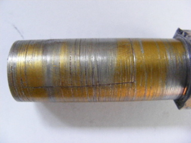
twybrow - 23/3/10 at 10:35 PM
On the first pic shown - what are all the circumferential scouring marks on the tube? That suggests to me it was spinning in the wishbone at some
point - either when in use, or during installation. Anyone else care to comment?
mistergrumpy - 24/3/10 at 12:53 AM
quote:
it amazes me how many people are ready to start screaming for a product withdrawal / recall / bad design causing failure etc!! Ridiculous really!!
+1.
turbodisplay - 24/3/10 at 07:42 AM
Not really, if it is made out of ali, which it looks like but no one person actually confirmed, it probally will fail again.
Ali will fatigue, as the millage goes up it will happen again.
My brake brackets were made out of steel, as I want to err on the side of caution, even though the calipers themselves are ali.
The difference is that ap racing will have stress tested and specified the correct grade of ali.
Darren
Staple balls - 24/3/10 at 07:55 AM
quote:
Originally posted by turbodisplay
Not really, if it is made out of ali, which it looks like but no one person actually confirmed, it probally will fail again.
The difference is that ap racing will have stress tested and specified the correct grade of ali.
I thought it was confirmed repeatedly that it was aluminium, and that it was HE30 6082.
Course, it'd be a shame to let facts get in the way of a good bit of drama 
[Edited on 24/3/10 by Staple balls]
iank - 24/3/10 at 08:01 AM
quote:
Originally posted by turbodisplay
Not really, if it is made out of ali, which it looks like but no one person actually confirmed, it probally will fail again.
Ali will fatigue, as the millage goes up it will happen again.
My brake brackets were made out of steel, as I want to err on the side of caution, even though the calipers themselves are ali.
The difference is that ap racing will have stress tested and specified the correct grade of ali.
Darren
+1
The concern is that they will all fail at some point in the future due to the properties of aluminium and/or the design.
So that's 999 more cars having their wheels fall off at some unknown point in the future. How many deaths could that cause? Might even attract
the attention of the red-top press to 'those lethal homemade cars' at which point politicians start trying to ban our hobby.
Paul TigerB6 - 24/3/10 at 08:16 AM
quote:
Originally posted by turbodisplay
Not really, if it is made out of ali, which it looks like but no one person actually confirmed, it probally will fail again.
Ali will fatigue, as the millage goes up it will happen again.
But as said there are various grades of ali so you cant just make a sweeping generalisation as soon as ali is mentioned. If that was the case then
there's thousands of planes all made out of ali that are all going to fail at some point. Thing is though they all have a certain life and to me
these camber adjusters probably should be treated the same - as a service item that you replace after x,000 miles.
I just think its a shame that rather than contact Rally Design who may well have considered the failure as something they wish to delve into and pay
for structural analysis on the failed part, that its been decided to try and destroy the reputation of this part and potentially damage their
business!!! This is a one off failure as far as anyone knows - if someone is so concerned about preventing failure again then why havent they spoken
to Rally Design????
eddie99 - 24/3/10 at 08:20 AM
quote:
Originally posted by Paul TigerB6
quote:
Originally posted by turbodisplay
Not really, if it is made out of ali, which it looks like but no one person actually confirmed, it probally will fail again.
Ali will fatigue, as the millage goes up it will happen again.
But as said there are various grades of ali so you cant just make a sweeping generalisation as soon as ali is mentioned. If that was the case then
there's thousands of planes all made out of ali that are all going to fail at some point. Thing is though they all have a certain life and to me
these camber adjusters probably should be treated the same - as a service item that you replace after x,000 miles.
I just think its a shame that rather than contact Rally Design who may well have considered the failure as something they wish to delve into and pay
for structural analysis on the failed part, that its been decided to try and destroy the reputation of this part and potentially damage their
business!!! This is a one off failure as far as anyone knows - if someone is so concerned about preventing failure again then why havent they spoken
to Rally Design????
+1, and also delete this thread and continue conversation in old one!
ReMan - 24/3/10 at 10:03 AM
+2
Whatever the rights or wrongs of this it is important enough to keep it in one thread for reference
Fozzie?
turbodisplay - 24/3/10 at 11:00 AM
Firstly I`m not looking to affect anyones business, it is because of the dangers involved if it does fail that concerns me. Surely that is what
everyone should be thinking about?
One important point is anodising makes the ali more brittle.
And why would you say it is a servicable item, how many people would buy a tintop where the suspention parts has to be changed (appart from bushes and
ball joints).
RE: One failure in 1000, or 0.1%.
If tap water was poisonous for 0.1% of the time then it would be undrinkable for 86 seconds a day. How many people would accept that?
Darren
[Edited on 24/3/10 by turbodisplay]
Liam - 24/3/10 at 02:22 PM
Hmmm what's going on here? Original thread has gone, but this one is reporting 5+ pages which it doesn't actually seem to have?? Hopefully
some sort of merger in progress rather than censorship, as this absolutely should not be swept under the carpet. EDIT: All fixed cheers
Chris!
The fact that 'only' 1 of these has failed (which could have easily resulted in a fatal crash) is really a completely separate issue to
whether or not the part is poorly engineered. Even if none had failed, any engineer worth his salt would have serious questions regarding the
material choice for that part, given its dimensions and the details of its application. The fact one has failed merely reinforces the point
made by many that that part in aluminium is simply not fit for purpose!
Thing is there are so many reasons that could be listed for not using aluminium for that part, yet practically none in favour (a possible small cost
saving in machining and saving, say, 20g or so is all I can think of!). So what baffles me is why on earth was ally specified in the first place?
Then we get these attempts to justify it saying it's a 'good' grade of ally, dubious static tensile tests which completely fail to
address the real reason for the failure - fatigue, and redesigns of the already perfectly fit for purpose wishbone to allow the weak unfit for purpose
adjusters to fail relatively safe. All this misses the point that the choice of material was just wrong in the first place, and the obvious solution
to all the many issues created by that choice is simply to make the thing out of steel, which it should have been in the first place!
Liam
[Edited on 24/3/10 by Liam]
ChrisW - 24/3/10 at 02:57 PM
We screwed up during the merge and managed to delete the original thread.
I am restoring from backup now.
I'm going to close this thread. Please DO NOT start another. Just be patient, the old one will appear again shortly.
Chris
ChrisW - 24/3/10 at 03:16 PM
Ok, now fixed. All discussion in the same place!
Chris
boggle - 24/3/10 at 03:54 PM
materials are not my speciality, but 6082 is not a very soft alloy....it doesnt like being bent
Neville Jones - 24/3/10 at 05:55 PM
Now, I've just had a u2u from RD, basically telling me to pull my head in over certification.
But, a responsible company such as RD, must surely have had these items independantly tested and certificated, before putting them on the market.
Mustn't they???
Obviously not.
Publish the test certificates, if you have had these things independantly tested and certified!!!
No certification, then you pull your head in, and stop telling everyone how good your stuff is, when you don't even know yourselves!! Act
responsibly, and get any critical items independantly checked, to acknowledged standards.
Cheers,
Nev.
arriba - 24/3/10 at 09:59 PM
What part on a locost is independently tested?
Toltec - 24/3/10 at 11:29 PM
To make this quite clear again.
Just before the adjuster pulled out of the wishbone I had done a a full left to full right lock right hand u-turn without the wheel falling off. It
was only when I reversed with almost full right lock that the wheel pulled free. I tried to see if I could slip the broken adjuster back into the
wishbone by pulling the top of the wheel out far enough. I did this with the wheel pointing forwards and while I could get the wheel far enough out
to place the end of the ball joint thread and adjuster at the end of the wishbone tube the angle between the tube and adjuster would not permit the
parts to slide back together. The head of the adjuster was not on the road where I had turned around or reversed, I spent some time looking for it,
so it had definitely gone before I started to reverse and it came free.
I do not have a car to test this on, however I would surmise that it would be quite difficult to pull the adjuster out over quite a range of wheel
positions. It may even be that reversing with plenty of lock is needed.
The other point to note is that the car has barely done 50 miles so it is not a long term fatigue issue in the sense that cars that have had these
for some time may start to see failures. We do not yet know why this adjuster failed so quickly when other owners have no doubt done thousands of
miles on them.
Perhaps RD needs to see the failed one and even consider checking some with a few miles on for cracks. Now I wonder who might have a X-Ray machine
handy, Ash?
boggle - 25/3/10 at 09:54 AM
if the parts are sold for motorsport use only then i dont think they need to be certified...
is there any smal print that says not for road use???
its a great get out clause for people...
Neville Jones - 25/3/10 at 10:12 AM
quote:
Originally posted by arriba
What part on a locost is independently tested?
Now you are getting pedantic. Still doesn't exonnerate you from responsibility.
You're selling parts as 'Fit for Purpose', when, quite obviously, they seem not. You have had no testing done to assure yourselves or
the public, that the parts in question are safe, or 'Fit for Purpose'.
If I was minded to buy some of the parts in question, fit them to a car in the prescribed manner, then have them fail with frightening results, then
send those legal people who advertise on TV after you, well, you'd be bankrupt. Far worse if I were a yank. I am in a position to do it, do you
want to take the risk?
There's a big difference between Joe Bloggs making parts for his car in ignorance, and a reputable company selling parts as Fit for Purpose.
Do yourselves a favour, and the car world, by getting these parts independantly checked by an SAE accredited Chartered Engineer in the least, and
fully tested at best.
Cheers,
Nev.
arriba - 25/3/10 at 12:14 PM
Neville Jones....I am intrigued you list your location as Matthew Town...is that the same Matthew Town,listed as the capital of Great Inagua
island,Bahamas?....Wikipedia says that the population of approx 1,000 people on the island largely live in Matthew Town and are employed mainly by the
Morton Salt Company. Must make you something of a celebrity driving a locost around that tiny island?
Neville Jones - 25/3/10 at 02:34 PM
On the contrary, a locost gets lost among the pimped up new cars the locals drive. None of them work, so how they get the money is beyond me. They all
seem to have a connection with the local airport, which has the busiest runway between 2.00am and 5.00 am of any in the world, and none of the
incoming or outgoing planes seem to be able to fly higher than about 200ft. Very odd.
Morton Salt are good payers, as are the Govt over here. Extremely good fishing, and the biggest crays you'll find anywhere. 
And the mosqitoes trained Douglas Bader, are bigger than spitfires, and drown out any plane engine! I've had to have the remains of a few of
their bites removed surgically, true!.
Cheers,
Nev.
[Edited on 25/3/10 by Neville Jones]
prawnabie - 25/3/10 at 06:37 PM
Neville always crops up when there is a bullet to fire - well either him or his alter ego syd bridge.
sebastiaan - 30/1/12 at 06:53 PM
And another one: Link to WSCC forum
Be careful with these, guys...
Neville Jones - 31/1/12 at 05:17 PM
All proved true in good time.
Now wait for the RD ali uprights to start breaking. May be a year or so.......maybe not.
If not made from the proper metal, and propely post treated, the crystallisation will creep up, then bang. I've seen it in other places with
similar material and loads.
Cheers,
Nev.
paulf - 31/1/12 at 10:00 PM
That is very poor design, the only way I would use an alloy part in that situation would be if the thread of the suspension joint came right through
the full length , even then the shoulder for the hex adjuster could be a weak point.The wall thickness only looks to be about 3mm minus the thread
depth and even steel would be marginal to use in that layout.
Paul
quote:
Originally posted by sebastiaan
And another one: Link to WSCC forum
Be careful with these, guys...
flak monkey - 1/2/12 at 09:02 PM
The ali adjusters work out to have a roughly 1.5 tonne minimum UTS dependant on the alloy they are being made from, could be as high as 2.5 tonne.
Pretty low especially if you crank the lock nut up too hard. Infact you could break them pretty easily just by tightening the nut up with a decent
sized spanner.
Mild steel ones work out at 5.1 tonnes UTS and no fatigue to worry about.
CSA of the adjuster is 117mm^2 (based on 21.75 OD and 18 ID) so equivalent to a 12.2mm solid bar. 430MPa UTS for mild steel.
[Edited on 2/2/12 by flak monkey]
flak monkey - 8/2/12 at 09:18 PM
Done some more maths one this one. Ok you have to make some assumptions, but it should put some numbers on it.
Assume a loaded and wet weight of 700kg for seven type cars.
The peak tensile load in the adjuster in normal use is during cornering, on the outside tyres. If you assume 70% weight transfer to the outside
wheels, and a 50:50 weight distribution, which I would suggest is fairly typical then the load at the contact patch of the front tyre would be in the
region of 245kg.
On slicks the coefficient of friction could be as high as 1.2, a typical road tyre would normally be a maximum of 0.8 however.
Commonly used g load profiles for road cars is 5-4-3 for durability, so allowing for impact loading beyond normal usage. 5g bump, 4g braking, 3g
lateral. Track cars commonly use 3-2-1 load profiles.
So the horizontal load at the contact patch is in the region of 882kg with this worst case load profile (245kg x 3g x 1.2)
This load acts as a lever on the wheel, essentially applying a torque which is compressing the bottom wishbone and putting the top one under tensile
load. This load has to be carried by the adjuster. I can't see any other situation which applies a significant tensile load to the adjuster.
This is a really rough sketch showing the general layout.

Rolling radius of a typical tyre combo for a seven type car is 225mm. Applying the force at the contact patch, would generate the resultant motion
indicated by the arrows x and y, which would result in a tensile force being applied to the adjuster.
The other vertical line is the upright, the leverage from the wheel is applied at a distance away from the pivot centre of the ball joints (~60mm)
which would be the stub axle in reality. It's a worse case to assume the top and bottom ball joints are only 100mm from the axle centre, I know
this distance is greater, but increasing it would decrease the load on the adjuster anyway. Also ignored is the vertical load on the wheel/tyre, which
would also reduce the force on the adjuster, by providing a moment in the opposite direction, although its much smaller. Again trying to make this a
worse case situation, so this load is being ignored.
So there's some simple leverage going on, some number crunching and the load at the adjuster would be in the region of 2050kg with the load case
above. Increase the distance from the axle to the top balljoint and the load decreases.
That's with a 3g lateral load profile, which you might see in a kerb strike situation, but not under normal driving conditions.
With a steel adjuster that gives you a 2.5x safety factor, including the 3g load profile. Aluminium is more marginal depending on specific alloy and
heat treatment.
Feel free to agree, disagree, or otherwise.
My mild steel adjusters saw 3 kerb strikes in my time of owning the car, and 8000miles. No problems.
[Edited on 8/2/12 by flak monkey]
Neville Jones - 9/2/12 at 12:08 PM
David, your numbers look about right on quick perusal. Just shows what really is going on. Impact loads could be a factor or two higher.
Unfortunately, most on here aren't engineers and schooled to do the numbers. Not the least of whom are the shopkeepers, and apparently one or two
who call themselves ex or present 'F1 engineers'. Got to ask why the 'ex' though?
Cheers,
Nev.
Hellfire - 9/2/12 at 12:50 PM
All you need to do now David, is start your production run of mild steel adjusters, price them competitively and I reckon you could make a few quid
out of them.
Not sure if the math is correct and to be honest, I CBA to check it either but the fact that you've considered the loadings and applied some
numbers to it, gives me more confidence in your mild steel adjusters than the aluminium ones we have fitted at the moment.
Just two questions.......
How would you protect mild steel adjusters from corrosion & how much are you charging for a pair?
Phil
flak monkey - 9/2/12 at 12:54 PM
quote:
Originally posted by Neville Jones
David, your numbers look about right on quick perusal. Just shows what really is going on. Impact loads could be a factor or two higher.
Unfortunately, most on here aren't engineers and schooled to do the numbers. Not the least of whom are the shopkeepers, and apparently one or two
who call themselves ex or present 'F1 engineers'. Got to ask why the 'ex' though?
Cheers,
Nev.
Thanks Nev. I really appreciate your input on this.
With respect to the aluminium adjusters. I know people have quoted HE30 material spec for these, but no one has said what the heat treament spec is,
if any. To give you an idea these are the UTS figures for HE30 in various states and the UTS of the adjusters in each material:
HE30 T4 - 205MPa - 2444kg (47% mild steel)
HE30 T5 - 270MPa - 3220kg (62% mild steel)
HE30 T6 - 310MPa - 3697kg (70% mild steel)
But that certainly doesn't take into account any fatigue cycles on the adjuster, and you can see from my previous calculations those high loads
are going to eventually fatigue the adjuster and cause it to break. I can do some theortical fatigue cycle calculations, but its not going to be that
accurate. The thin section just doesn't lend itself to manufacture from most grades of aluminium, even those with similar UTS figures to
steel.
I have tried to make my calcs a worst case to see how much leeway there is until the UTS of a steel adjuster is reached. Based on the calculations and
my road testing with my own car I wouldn't use them made of anything other than steel.
The other significant tensile load on the adjuster is provided by the lock nut. This could easily be in the region of an additional 500-600kg with a
correctly torqued locknut (~15-20lbft). Overtightening it would see this figure increase significantly.
flak monkey - 9/2/12 at 01:00 PM
quote:
Originally posted by Hellfire
All you need to do now David, is start your production run of mild steel adjusters, price them competitively and I reckon you could make a few quid
out of them.
Not sure if the math is correct and to be honest, I CBA to check it either but the fact that you've considered the loadings and applied some
numbers to it, gives me more confidence in your mild steel adjusters than the aluminium ones we have fitted at the moment.
Just two questions.......
How would you protect mild steel adjusters from corrosion & how much are you charging for a pair?
Phil
Phil,
I fitted mine to the car bare steel, just with a light coat of oil and they never really got that rusty to be honest. But you could just give them a
coat of paint at the hex end to protect them.
I have recently made a few sets and revised the design again, leaving the hex end closed off and the threaded hole drilled to a depth of 50mm. This
still allows the full range of adjustment on the joint, but makes the adjuster solid at the point where you have the stress raiser of the hex meeting
the wishbone tube. This won't afftect the UTS of the adjuster, but its another minor design flaw (in my opinion) adressed.
Neville Jones - 9/2/12 at 04:41 PM
I've been making these out of EN16, a few lengths of imperial hex I inherited from a local aircraft parts maker. Also been making steering
extensions and other bits out of it. Easily machined as well. I'll be needing some more soon, so have to track some more down.
Cheers,
Nev.
alfas - 11/2/12 at 09:39 PM
lets see things from another view:
how often you need to adjust the camber?
is it so difficult to take off the ball-joint for adjustment?
so the final question is: do i really need such an camber adjuster???
and do i really need to buy those cheapish china-made items at RD?
Chippy - 11/2/12 at 11:17 PM
I have the alloy ones fitted, and did have to adjust the camber several times before landing on the correct, (for my car), degree of camber. Car has
done more than 6000 miles, most of which at a fair lick, especially on the twisty bits and no problems to date. Cheers Ray
Hellfire - 13/2/12 at 12:51 PM
quote:
Originally posted by alfas
lets see things from another view:
how often you need to adjust the camber?
is it so difficult to take off the ball-joint for adjustment?
so the final question is: do i really need such an camber adjuster???
and do i really need to buy those cheapish china-made items at RD?
The reason for fitting camber adjusters is to enable you to get accurate camber. It isn't particularly difficult to remove the balljoint but
without screwed camber adjusters, you are limited to adjustments of one full turn of the balljoint, which may not give you the desired camber for your
application.
It makes adjusting camber on trackdays much easier.
Whether you really need camber adjusters or not, is a question only you can answer...............
Having seen the aluminium ones fail, we will be replacing the ones we have with mild steel items. It's a small price to pay for 'peace of
mind' and I dread to think what the consequences would be if our aluminium adjusters should fail.
Phil
wylliezx9r - 13/2/12 at 01:11 PM
I had a failure on my rear near side wishbone whilst exiting a round about, luckily I wasnt going to fast. The botom wishbone rose joint held on
luckily and the wheel didnt come off. I have since replaced all four with mild steel ones. It could have been a lot worse had the failure been on a
front wheel at speed etc. In my opinion aluminium ones shouldn't be for sale, they could easily end up killing somebody.
wylliezx9r - 13/2/12 at 01:26 PM
These are the ones to get : Camber Adjusters Steel Front Top wishbone Kit Car Locost haynes roadster super 7 | eBay
[Edited on 13/2/12 by wylliezx9r]
Chippy - 13/2/12 at 05:09 PM
quote:
Originally posted by wylliezx9r
These are the ones to get : Camber Adjusters Steel Front Top wishbone Kit Car Locost haynes roadster super 7 | eBay
[Edited on 13/2/12 by wylliezx9r]
Well despite the alloy ones having been OK for 6 Years, I have just bitten the bullet and purchased a pair of the above, better safe than sorry,
Cheers Ray
sebastiaan - 13/2/12 at 05:42 PM
Are these Flak's? (in the Ebay link) I'm sure most of us would rather buy from a fellow LB'er...
flak monkey - 13/2/12 at 05:54 PM
Nope they arent mine.... no idea who is making them to be honest
I can't do them for that price though....economies of scale n all that. So if someone else is offering them cheaper, that's that... there
wasnt anyone doing them in steel when I atarted making them.
Chippy - 16/2/12 at 03:49 PM
Well despite my post earlier, this is what I found when changing to the steel one from Ebay.
[img]

Adjuster crack1
[/img]
[img]

Adjuster crack2
[/img]
The crack can be clearly seem on the inside, but despite trying to take a picture it didn't show due to lack of light I guess. So be carefull out
there. Regards Ray
Plus foregot to add these are GTS ones.
[Edited on 16-2-12 by Chippy]
AdrianH - 16/2/12 at 04:00 PM
quote:
Originally posted by Chippy
Well despite my post earlier, this is what I found when changing to the steel one from Ebay.
That looks as though there were cracks forming following the cut threads. You were wise to change them. After 6 years I guess any metal could
move around slightly within the tube and wear.
Personally glad I don’t use any such things despite having no fine adjustment.
Adrian
ashg - 16/2/12 at 11:53 PM
so thats 4 people now then!
sadly i think someone will need to have a big accident before the ali ones are withdrawn from sale.
on a plus note the steel ones i made 2 years ago after my ali ones failed have held up to thousands of miles over all types of surfaces.
flak monkey - 18/2/12 at 02:06 PM
I would and do thoroughly recommend to anyone buying/using quick camber adjusters that they check them regularly for any early signs of problems
whether they are aluminium or steel. I would also only really recommend them for track use.
EN1A adjusters should be more than adequate for use on a sevenesque type car, but if they are subjected to any curb strikes do check them out.
The above pics of the aluminium ones dont really suprise me and I would urge anyone running those ones to check them out sooner rather than later.
I was recently told that the aluminium ones can also be quite a loose fit inside the wishbone tube, not a great idea as it means they have room to
move around and it makes the potential for problems much greater.
Obviously the choice of what you use on your own car is down to you.
I don't know of anyone who's using steel ones to have had a problem, and I know lots of people have made their own too having read about the
aluminium ones failing.
phelpsa - 18/2/12 at 02:20 PM
The whole design (whether ali or steel) is compromised by that fact that you are taking both the preload and a the wishbone force through a series of
stress raising features.
I did some FEA investigation and decided that even in steel to be really safe I needed at least 3mm of material external to the thread OD with a cut
thread and a 0.8mm radius at head of the adjuster. In 6082 T6 ali you would ideally want a 2mm rad but you'd have to fatigue limit the thread.
That is assuming that the rod end doesn't reach the end of the adjuster (ie you're not using all the thread) which is quite normal in these
circumstances I believe.
I wouldn't be willing to publish the results (FEA is only as good as the numbers you put in obviously...) but those were the conclusions that I
drew.
EDIT: That was using a 5/8 UNF rod end rather than an M18x1.5 track rod end, but the results should be similar
[Edited on 18-2-12 by phelpsa]
[Edited on 18-2-12 by phelpsa]
Chippy - 18/2/12 at 03:20 PM
quote:
Originally posted by phelpsa
That is assuming that the rod end doesn't reach the end of the adjuster (ie you're not using all the thread) which is quite normal in these
circumstances I believe.
[Edited on 18-2-12 by phelpsa]
Yes thats a true statement, the crack that you can see in the pictures that I posted above, where it turns to go round the adjuster is where the
thread ended, or almost. The other circular marks are not cracks but where the adjuster was screwed in causing the anodizing to be scored. Regards Ray
britishtrident - 18/2/12 at 03:24 PM
Woods and trees --- It is an adjuster not a nut , the is the part is being used incorrectly without a backing nut; ie a half nut
at one end and a Nyloc or Symonds nut at the other., You might get some fretting where the tube contacts the alloy but there is no chance of
catastrophic failure.
phelpsa - 18/2/12 at 03:34 PM
quote:
Originally posted by britishtrident
Woods and trees --- It is an adjuster not a nut , the is the part is being used incorrectly without a backing nut; ie a half nut
at one end and a Nyloc or Symonds nut at the other., You might get some fretting where the tube contacts the alloy but there is no chance of
catastrophic failure.
/ BT in factual post shocker
flak monkey - 20/2/12 at 07:04 PM
Steel adjusters are approx 30% stronger than aluminium adjusters made from HE30/6082 T6 with a lower risk of fatigue failure.
But I would absolutely recommend that camber adjusters must fitted to a wishbone with a top tube similar to that shown in the attached image which has
a retaining lip at the outer end. This would safeguard the location of the top ball joint should the worst happen and an adjuster fail. And give some
warning without catastrophic failure as the adjuster nut would be loose on the inner end on inspection.
I really would emphasis that they should not be used on road vehicles and the top wishbone be of the more traditional design with a threaded tube as
supplied by most manufacturers.
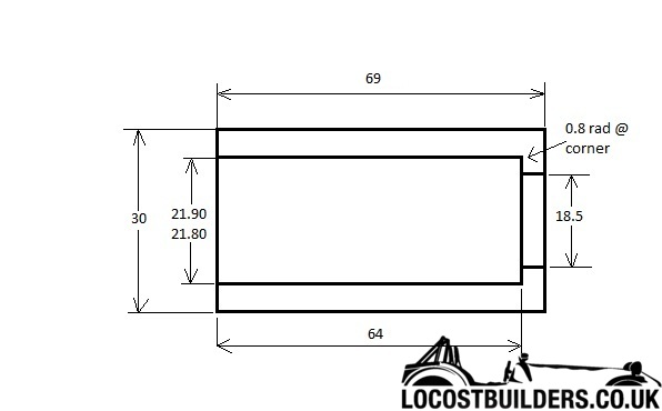
Neville Jones - 21/2/12 at 10:31 AM
quote:
Originally posted by britishtrident
Woods and trees --- It is an adjuster not a nut , the is the part is being used incorrectly without a backing nut; ie a half nut
at one end and a Nyloc or Symonds nut at the other., You might get some fretting where the tube contacts the alloy but there is no chance of
catastrophic failure.
Oh dear, we're thinking we are an engineer again, aren't we Mr.BT?
These 'adjusters', in the configuration intended, are essential and structural, and very much load bearing.
What happens if you take the sleeve out? You can't fit the balljoint. Sleeve is essential and structural.
What happens when not locked? the whole lot slaps around like a doodah in a street ladies money maker.
The safest solution is as Flak says, and do without the fine adjustment, and suffer the minute amount of camber different to the ideal you were
seeking. As if anyone here(myself included) would feel the difference. Well, unlees someone on here is an F1 or top Lm driver,
Cheers,
Nev.
mad-butcher - 22/2/12 at 05:12 PM
I've just ordered a set off the above link
but if your looking to make your own these are great value for money eBay - The UK's Online Marketplace tubes are as
per above diagram
[Edited on 22/2/12 by mad-butcher]
flak monkey - 22/2/12 at 07:55 PM
Those are extremely good value. What you can achieve with CNC machines though
And they have considered the issues I highlighted above.
mad-butcher - 22/2/12 at 08:17 PM
spoke to a mate who does a bit of lathe work and he say's he couldn't even justify buying the material and switching the lights on at that
price just to make the tubes never mind the extra work making the adjusters
tony
flak monkey - 22/2/12 at 08:23 PM
Yep, thats the thing. Making a set of just the inserts on a manual lathe, to reasonable accuracy takes around 20-30mins.
If you have an equipped workshop with OH's to pay as well (heating, lighting, rect etc), at Ł40-50/hr plus materials then its not possible to
make things for what people are willing to pay a lot of the time.
Making a set on a CNC machine would take less than 10 mins. If you have 2 then you could make the adjusters and tubes in the same time.
As Metallica once said, Sad but True...


