britishtrident
|
| posted on 17/4/04 at 06:30 AM |

|
|
quote:
Originally posted by NS Dev
Just to throw yet more petrol on the bonfire!! Just been looking at some Westfield wishbones and the shocker mounting point looks the same as the
"book" locost one (without the benefit of a ruler)
Also just put the deposit on my Stuart Taylor IRS chassis/body set.
Locost chassis =original prelit narrow body Westfield in all but a couple of very minor details
|
|
|
|
|
NS Dev
|
| posted on 17/4/04 at 09:13 AM |
|
|
sorry to keep the bonfire going then but does that not contradict this????
quote:
Originally posted by cymtriks
Quote from earlier post
"Caterham have used 3/4" tube for 30 years with few failures, yet further up the thread a "calculation" showed that these
would bend at 3g accel on the wishbone, I just don't buy this. If it were right then all westfields, Caterhams plus all the locosts would have
broken!!!!!!!!!!"
And if they had been designed along the lines of the Lowcost wishbone a lot of them WOULD have broken. A 3g bump is roughly the upper limit for normal
road use. The calculation is telling the truth. The Lowcost book wishbone isn't up to the job, especially if you're going to give it some
serious use.
If you look at a Caterham wishbone you'll see that the spring is mounted much closer to the wheel upright which greatly reduces the bending
forces on the wishbone.
Another quote
"If you consider the lower shockabsorber mounting position for a moment, if it were positioned at the lower balljoint position then the lower
wishbone would have zero bending stress on it, it would be purely tension/compression."
Correct. Do I detect a basic knowledge of beam theory here???
"The shocker is mounted very close to the lower balljoint, the stress in bending is not that great..."
It isn't. It's mounted much further from the lower ball joint than a Caterham.
"the stress under braking however, is very great! Curbs on most tracks have the ability to bend even tough suspension components if you clip
them with the wheels loaded up (rather than unloaded as is the case with the inside wheels when "curb-hopping" "
....Maybe. The rear arm of the lower front wishbone is often the most highly stressed part of a car suspension.
I take the point that longitudinal, as opposed to vertical, forces may be the culprit. My calculations still show the relative strengths of the common
tube sizes. I'd recommend using 1 inch diameter tube for a Lowcost book wishbone.
If (as BritishTrident correctly says) the westfield prelit wishbones are the same as the locost (as good as anyway) and therefore the Caterham too (as
they were a copy, hence the litigation!) then surely my point about the design holds?!
|
|
|
craig1410
|
| posted on 17/4/04 at 09:43 AM |
|
|
Hi,
Here's a sire showing some nice pics of a Westfield chassis for comparison. It certainly does look very similar to the Locost...
http://home.iprimus.com.au/flaherty/westfield/index.htm
Cheers,
Craig.
|
|
|
britishtrident
|
| posted on 17/4/04 at 09:49 AM |
|
|
quote:
snip
If (as BritishTrident correctly says) the westfield prelit wishbones are the same as the locost (as good as anyway) and therefore the Caterham too (as
they were a copy, hence the litigation!) then surely my point about the design holds?!
errr no I did imply Locost wishbone were copies of Westfield -- I dont know if extent of the copy the extended to tube wall thickness.
Westfield wishbones are totally diferent from any used by Cateham or Lotus.
The history behind this
Original Seven S1 used Hillman Minx king pin style uprights (as on original Elite) which were quickly changed for smaller lighter Triump Alford &
Adler units.. The Triumph upright has a ball joint at the top but a threaded bronze trunnion with delrin bushes at the bottom.
S1 Lotus started out with a steering box but modified to use a steering rack mounted behind the axle centre line. Together with the positioning of
steering arms used this gaves toe-in in turns as used on the Lotus 18 racing car.
S2 Moves steering rack to where it is on current Cateham (and Locost) ahead of axle centre giving more conventional semi-akerman geometry..The
suspension was tidy up a bit but remained much the same through the S3 and first 20 years of Caterhams.
S4 Used Triumph uprights but with Europa lower wishbone and I think baby Elan upper wishbones.
Caterham later models -- anti-roll bar now seperate from upper wishbone, lower wishbone redesigned.
Westfied -- Original cars (7 & 11) based on MG Midget/A-H Sprite used king pin suspension, with very nicely designed fabricated wishbones.
Due to shortage of donors this was adapted to Cortina ball joint suspension, the adaption was not so carefully thought out or detailed as the
original Sprite based Westfield suspension -- hence massive bump steer. This later Westfield suspension is very similar to the book Locost but as I
said I don't know if this extended to checking the tube thickness -- I suspect not.
Also the pre-lit Westfield/Locost chassis is not anything like a Caterham chassis. Caterhams law suit was based on the ancient offence of
"Passing Off" .
[Edited on 17/4/04 by britishtrident]
[Edited on 17/4/04 by britishtrident]
[Edited on 17/4/04 by britishtrident]
|
|
|
NS Dev
|
| posted on 17/4/04 at 09:59 AM |
|
|
Ahhh, it's all becoming clear!
|
|
|
Peteff
|
| posted on 17/4/04 at 11:18 AM |
|
|
Pre lit Westfield was a C@terham copy
That's why they were sued for making it as Caterham had paid for the design from Lotus. I think the original case was amended to stop them using
the '7' as it was copyrighted. It was smaller than the present chassis which is almost a Locost chassis. A friend down the road has a live
axle Westy and without the bodywork on you could not tell it from a Locost and the suspension parts are very similar. The bar across behind the seats
where the roll bar and rear shock top mounts is 2"x1" and is a solid bar not a tube, that's about the only difference. The front
wishbones on a Caterham are totally different and look spindly compared to locost with only a tube joining the two sides but the shock mount is at the
very end near the joint and bolts through the sides with a strengthening spacer tube.
http://cgi.ebay.co.uk/ws/eBayISAPI.dll?ViewItem&item=2473427458&category=9886
Look at these before they go.
[Edited on 17/4/04 by Peteff]
[Edited on 17/4/04 by Peteff]
yours, Pete
I went into the RSPCA office the other day. It was so small you could hardly swing a cat in there.
|
|
|
eddymcclements
|
| posted on 17/4/04 at 12:19 PM |
|
|
In reply to the original question, here's my tuppence worth....
Both the original wishbone of unknown origin and its replacement have failed in similar ways - this reduces the possibility of a faulty component.
Components common to both failures are:- hub, upright, damper/spring, top wishbone and chassis. The wheel/tyre combination was changed and the dampers
were softened.
Under braking the lower wishbone rear tube is in compression, but if the tube is perfectly straight it ought to be able to withstand high forces
without bending.
Chris_G says that the damper isn't bottoming out - I assume this has been checked with a tie-wrap round the damper rod, a brisk drive round a
challenging route and a subsequent check of the position of the tie-wrap to make sure it's not been pushed right up against the top bump-stop.
If it hasn't, then the damper isn't bottoming out, however (and this has already been mentioned) this doesn't prove that the spring
isn't going coilbound.
Roll a piece of blutak into a fat snake, wrap it round one of the spring coils and go for the brisk drive again. On your return check to see if the
"snake" has been nipped in two by the coils touching each other - although the damper has been softened you don't say if the springs
have been changed, nor what their rate and free length is. From the photo I have to say that it looks like a 6" spring has been fitted where a
7" or 8" spring might be better.
When a spring goes coilbound the damper/spring becomes totally solid, and you've just hit a bump then something else has to give. On the book
design the shock mount on the lower wishbone is a lot further from the bottom balljoint than on, say, a Caterham. A high instantaneous loading (big
bump) coupled with a solid (coilbound) shock might be enough to cause a bent wishbone in exactly the place that this has occurred. Even if only a
slight bend appears initially, each time you brake you are feeding quite a large load into a tube which is no longer straight and whose resistance to
compression forces is drastically reduced.
Eddy
Edited to remove typos!
[Edited on 17/4/04 by eddymcclements]
|
|
|
britishtrident
|
| posted on 17/4/04 at 12:25 PM |
|
|
quote:
Originally posted by Peteff
That's why they were sued for making it as Caterham had paid for the design from Lotus. I think the original case was amended to stop them using
the '7' as it was copyrighted. It was smaller than the present chassis which is almost a Locost chassis.
snip
Westfield started building a Lotus Eleven replica to which nobody had any objections.
It then gave birth to the Lotus 7 S1/S2 replica, the chassis was almost identical to the Eleven replica and had all the features present in the book
Lowcost chassis but slightly narrower to suit the MG Midget axle..
The Lotus S3 chassis as made for Caterham at the time was a very sparse spaceframe, it was mainly made of 1.8 swg round tube with brazed joints.
Working from the front of the chassis the front bay of the spaceframe was very different from any Westfield because the suspension design was
completely different.
Apart from the different type of tube used the engine bay areas were similar on the Lotus/Caterham chassis and the Westie/Locost, however the big
difference starts from the front footwells back, the Lotus S3 chassis lacks any centre backbone structure --- I seem to remember the floor was
supported by 0.5" angle iron and the propshaft covered by a minimilist bit of bent 1.2mm alloy sheet with a curved steel plate where the diff
nose pokes into the passenger compartment.
The area to the rear of the passenger bulkhead is superficially similar on the Lotus chassis but because the Lotus/Caterham suspension dosen't
use a panhard rod the load bearing structure stops at the rear bulkhead and there is no triangulation.
Why Caterham had any case at all was because Chris Smith was selling the original Westfields as "a Lotus 7 S1 Replica" on the grounds that
Caterham had the rights to the S3 and S4 models but not the S1. I had a copy of the brochure and it actually stated in this . Gradually the Westie
became less 7 S1 like and more like a 7 S3 until Caterham sent for "lawyers guns and money". Caterham had a very shakey case on copyright
grounds because the two chassis were different and other spaceframe clubman cars had existed before and after the Lotus 7 was built, but they had much
better case on the lesser offence of "passing off".
When the matter was settled out of court the main terms were that original Westie chassis jigs brocken up and Westfield could no longer sell as a 7
replica and had to create thier own identity --- hence the new body work. However the new Westie SE chassis was essentialy just a very slightly
wider version of te original Westie 7 S1 chassis.
Looking back Westie came out the litigation significanly better than Caterham, the litigation put Westfield on the map, gave them street cred and
forced them to move more up market.
Interestingly post ligation Caterham chassis has changed significantly and has borrowed features found in other 7 style cars :-)
One other thing Caterham isn't the sole holder of rights to the 7 design, somebody in NZ has was producing S4 chassis powered by 907 engines
with a Lotus stamp of approval but the project stalled, and I suspect there may be others.
A question has also be raised as to wether Chapman had the personal ownership of the rights which sold to Caterham or if in fact they belong to the
Lotus Group. The complex business deals of "Chunky" and his mate Fred Bushell are a mystery of the grave however Caterham apparently paid
Chapman personally not Lotus Group, Lotus Cars, Lotus Components or Team Lotus.
[Edited on 17/4/04 by britishtrident]
[Edited on 17/4/04 by britishtrident]
|
|
|
craig1410
|
| posted on 17/4/04 at 02:12 PM |
|
|
Eddy,
I'm glad someone else agrees with my analysis... 
It seems the most likely explanation (coil binding that is) given the reasons you stated above. I never agree with second guessing an established
design, however marginal, when there is little history of failure of that part. Certainly you can get a one-off failure due to material defects or
poor workmanship but two in a row in exactly the same place seems unlikely to be caused by the item which is failing.
Good advice with the bluetak fat snake technique by the way. I think this would be very worthwhile trying and in any event a more appropriate set of
springs should be fitted whatever the outcome as these springs must be getting close to coil bind even if they prove not to be binding completely at
present.
Coil bind is most likely to happen under "continuous" force such as extended braking or cornering where the damper has time to move. If
you then had a bump of, say, 1 inch which would normally be absorbed without any trouble, all of this energy will go into bending something and due to
the design issues discussed earlier, the most likely place to bend is exactly where the failure is taking place.
If the car has been coilbound then you should carefully examine all of the other suspension components for bending and/or fatigue cracks. Also check
the mountings for same.
Cheers,
Craig.
|
|
|
NS Dev
|
| posted on 18/4/04 at 09:31 AM |
|
|
quote:
Originally posted by craig1410
Eddy,
I'm glad someone else agrees with my analysis...
It seems the most likely explanation (coil binding that is) given the reasons you stated above. I never agree with second guessing an established
design, however marginal, when there is little history of failure of that part. Certainly you can get a one-off failure due to material defects or
poor workmanship but two in a row in exactly the same place seems unlikely to be caused by the item which is failing.
Good advice with the bluetak fat snake technique by the way. I think this would be very worthwhile trying and in any event a more appropriate set of
springs should be fitted whatever the outcome as these springs must be getting close to coil bind even if they prove not to be binding completely at
present.
Coil bind is most likely to happen under "continuous" force such as extended braking or cornering where the damper has time to move. If
you then had a bump of, say, 1 inch which would normally be absorbed without any trouble, all of this energy will go into bending something and due to
the design issues discussed earlier, the most likely place to bend is exactly where the failure is taking place.
If the car has been coilbound then you should carefully examine all of the other suspension components for bending and/or fatigue cracks. Also check
the mountings for same.
Cheers,
Craig.
Couldn't agree more craig! you have pretty much hit the nail on the head that I have been trying to get over but getting shot down all the time!
As you say, the continuous loading of a corner and then running over a kerb at the exit perhaps would be the sort of situation where the spring might
go coilbound and bend something, possibly, maybe.......
|
|
|
craig1410
|
| posted on 18/4/04 at 12:10 PM |
|
|
Anyone fancy estimating the peak force exerted on the end of the wishbone assuming the spring has gone coilbound and assuming a 50mm bump is hit at
60MPH. Assume the bump is a saw tooth kerb with, say, a 50mm linear rise for 300mm travelled. Assume a static corner weight of 175Kg's and
obviously when coilbound there are no spring or damper effects to worry about.
The static loading would be about 1750 Newtons but under braking the weight transfer would increase this. I don't know how much weight transfer
you would get with a Locost but lets say the corner weight would increase to 200Kg's and use that figure for the bump impulse calculations.
If we figure out the force and then measure the distance between the tyre contact patch and shock absorber mounting this should give us the torque
being applied to the wishbone and from this we should be able to figure out the stress on the wishbone tube.
I'll have a go at estimating it later but duty calls (aka the wife)...
Cheers,
Craig.
|
|
|
Chippy
|
| posted on 18/4/04 at 10:53 PM |
|
|
As a new, read old, member of the Locost builders forum I would very much like to know if other builders have suffered the problem of the fron
wishbones bending. I have just attained my donor, a 1990 Sierrs 4x4 2.9i, and with that weight in the front would like to be sure that the front
isn't going to fold up.
|
|
|
NS Dev
|
| posted on 18/4/04 at 11:21 PM |
|
|
Don't know, but good point, I'm sure others have used this engine and it'll be about the heaviest you could put in there!
|
|
|
Chris_G
|
| posted on 28/4/04 at 10:25 PM |
|
|
UPDATE
Update time......
We tried the bluetack sausage experiment and found that there was no evidence of the coils even getting close to binding!
With the shock disconnected the wishbone/upright assembly moves freely throughout its travel!
So, onto some reinforcements. It was quite scary just how easy the original tube was to bend back straight again! (maybe this tells us what the
problem is!)Nick had some 1/4 inch thick steel angle iron seam welded to both bottom tubes and also across the plate below the shock mount. So far, so
good! We've been out on a few good blats together (me in my Westy as back-up!) and we were even prepared to go around Castle Combe on Saturday
but it was a bit busy there for our liking so with some fast road fun everything seems to be holding up.
Time will tell, but confidence is building once again
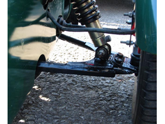 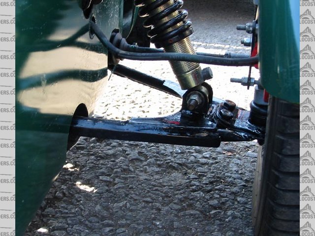
Rescued attachment wishbone mod1.jpg
|
|
|
Chris_G
|
| posted on 28/4/04 at 10:25 PM |
|
|
view from the front.....
 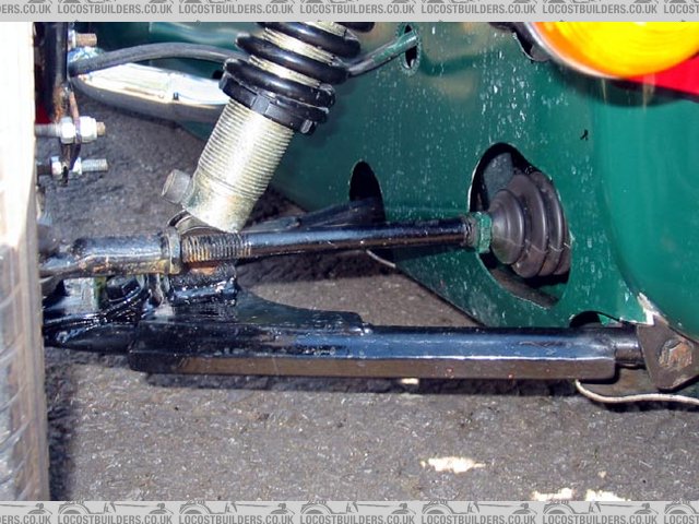
Rescued attachment wishbone mod2.jpg
|
|
|
skinny
|
| posted on 29/4/04 at 04:02 PM |
|
|
just thought i'd add my 2p, sorry if i am just re-hashing what has already been said, esp by trident, i am not trying to steal anyones
thunder...
the way i see it, the original failure could have been caused simply by hard cornering and an insufficient wishbone diameter.
i don't think braking, bumps, binding bushes, high sprung mass etc are at all to blame, it's a simple matter of geometry.
Talking about the outer (loaded) wheel here, under reasonable cornering, the wheel will be forced upwards relative to the rolling body, and this will
be resisted (with no roll bar) purely by the spring pushing it back down again. With this design, the wheel forces operate at the very end of the
wishbone, and the opposing spring forces are spread over the wishbone thru the plate.
so you have the inboard mount as your datum, approx 2/3 of the way along you have a significant component of spring force pushing downwards, and at
the other end you have the wheel forces pushing upwards. it seems fairly obvious that there are going to be large stresses doesn't it? the only
way to completely eliminate or cancel these moments is to have the suspension mounting point and the upright mounting point at the same location as
trident has said.
as far as i can see, with that design, it's perfectly sufficient any of only
1) excessive spring rate (not necesarily reaching full spring travel but of course this would accelerate the problem)
2)high mass and heavy cornering leading to a high roll angle
3) insufficient strength of wishbones
in various degrees would cause this to happen.
sorry if i am just stating the obvious or if i have made any glaring errors (just trying to collate my thoughts & finish this before i get off
work).
if you don't fail, you aren't trying hard enough.
|
|
|
drmike54
|
| posted on 29/4/04 at 04:19 PM |
|
|
Wishbone Bending
One thing that I have been wondering is what is the condition of the top shock mount? With all of this stress on the wishbone isn't the top
shock mount the fulcrum? Apparently the forces are high enough to bend the wishbone, yet not enough to rip the top shock mount off the chassis.
|
|
|
Alan B
|
| posted on 29/4/04 at 04:29 PM |
|
|
Skinny....yeah that's pretty much what I said early in the thread....
No need to look for mysterious scenarios...the basic design is flawed...too much bending (yes I know it largely can't be helped)
|
|
|
skinny
|
| posted on 30/4/04 at 08:37 AM |
|
|
yeah, sorry alan, you did say that too, as did a few others, just thought i'd agree with you all 
under cornering there would also be the lateral component adding (in a way - when the wishbone has deflected) to the bending moment which probably
wouldn't much help the wishbones.
just wondering, the bending stresses within the wishbone (due to cornering at least, tho of course not and dive under braking etc.) would be
significantly reduced with an anti roll bar mounted as close to the ends of the wishbones as possible. maybe you could get away with lower spring
rates then too?
[Edited on 30/4/04 by skinny]
if you don't fail, you aren't trying hard enough.
|
|
|
NS Dev
|
| posted on 30/4/04 at 10:36 PM |
|
|
quote:
Originally posted by Alan B
Skinny....yeah that's pretty much what I said early in the thread....
No need to look for mysterious scenarios...the basic design is flawed...too much bending (yes I know it largely can't be helped)
I know we are going round in circles again but if this is right, why haven't everybody's wishbones bent? There are a hell of a lot of
these cars about now!!!
Why the one off??
I can see the design problems (anybody with 1/2 an ounce of mechanical sense can) but if they are the sole cause then there would be many failures!!!!
|
|
|
Bigfoot
|
| posted on 1/5/04 at 02:06 PM |
|
|
Going round in circles is not necesarily a bad thing, it has been an interesting debate. Some good points have been made, but I am sticking to my
original opinion.
Way back in the thread my suggestion was that the part was simply not strong enough. I accept that it is made from the same materials as a successful
production part, but that does not make it as durable. Engineering is more subtle than that, if it wasn't, people like me would not make a
living.
With the benefit of experience, at first glance it does not look strong enough, even before you start to analyse it. If it holds together with the
extra bits welded on, that would surely confirm that it was simply not strong enough.
If that is the case you have two options, either make it from more robust materials, or design it better. Given that most locost builders do not have
the facilities to refine their designs to perfection, The sensible option is to build it stronger. there seems to be an unhealthly desire to make
these things too light, this isn't Formula 1, you really won't notice the difference of a few pounds in the type of driving you will be
doing. Does it handle any different since you welded the extra bracing on?
Cheers
Bigfoot
|
|
|
Alan B
|
| posted on 1/5/04 at 02:48 PM |
|
|
quote:
Originally posted by NS Dev
I know we are going round in circles again but if this is right, why haven't everybody's wishbones bent? There are a hell of a lot of
these cars about now!!!
Why the one off??
I can see the design problems (anybody with 1/2 an ounce of mechanical sense can) but if they are the sole cause then there would be many failures!!!!
Yes, good point. The lack of other failures is hard to explain.
|
|
|
Terrapin_racing
|
| posted on 4/5/04 at 02:10 PM |
|
|
You can also increase the strength of the standard dimension wishbones considerably by having them Nitrotec'd.
It's a fantastic process - I tried to destruction test a Terrapin wishbone post treatment - no chance. Also burnt out three TN treated drills
drilling a hole oversize!
Mine were done by Nitrotec in Birmingham (Steve Plum was the contact)
NITROTEC SERVICES
UNITS 5-8
WITTON INDUSTRIAL ESTATE
BICKFORD ROAD
BIRMINGHAM B6 7EF
TEL:0121 322 2280
http://www.nitrotec.co.uk/properties/properties_frames.htm
see chart:
When non-alloyed steels are rapidly cooled after Nitrotec treatment, strengthening of thin sections occurs. This results in an increase in both the
yield strength of the base material and its fatigue strength.
Yield Strength
The nitrogen enriched substrate that results after Nitrotec treatment enhances the yield strength of thin section component. With thin sheet metal
components this can be increased by up to 4 times for mild steel sheet materials. Parts produced in 3mm and 2mm thick materials can be reduced to
1.5mm and 1.mm thick material and in some instances as low as 0.5mm thick.
[Edited on 4/5/04 by Terrapin_racing]
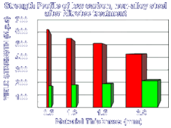 
Rescued attachment sprofiles_graph.gif
|
|
|
crbrlfrost
|
| posted on 4/5/04 at 04:21 PM |
|
|
Wouldn't that be the same as the older nitriding process used for crankshafts and such, with the exception that with thin sections you would be
hardening a greater percentage of the component (in thick sections it usually only penetrated 20thou or so). My concern would be the trade off between
strength and toughness as I'm sure some of these track cars could be subjected to relatively large impact loads. When the wishbone is used under
the fatigue limit with only a few mild strikes I wouldn't see an issue, but since we've generally come to the conclusion that its
underdesigned and probably flexing significantly, a hardened surface with increased brittleness would cause me some concern. But do keeps us posted,
I'm very curious.
|
|
|
britishtrident
|
| posted on 4/5/04 at 05:00 PM |
|
|
Re Nitrotec process looks like Tuffriding ie nitriding forn normal mild steel, personally I would be very reluctant to use it on a welded
component.
|
|
|