cd.thomson
|
| posted on 2/3/10 at 07:49 PM |

|
|
simple relay question
Hi guys, I have what I believe is a bog standard relay that I was going to setup to control my fan via thermostatic switch.
My twin horns came today though and I fancied having a play. Got one of the horns working directly off the switched wires. Now I have the relay set up
as below and realise I need to put some more electricity into the mix but where?
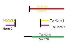 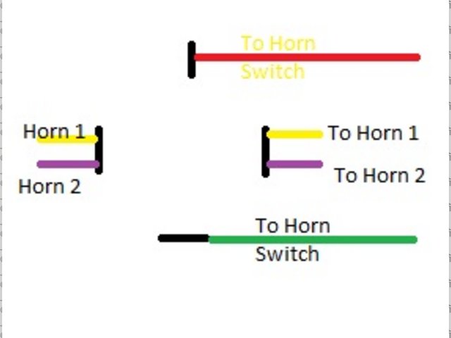
Rescued attachment horn relay.jpg
Craig
|
|
|
|
|
BenB
|
| posted on 2/3/10 at 07:56 PM |
|
|
The relay should have numbers on the terminals and that allows you to work out which bit needs the juice 
|
|
|
Steve G
|
| posted on 2/3/10 at 07:57 PM |
|
|
Do you have any numbers on relay terminals??
You need a fused feed going into each circuits (on the diagram imprinted on the relay with numbered terminals) so go into one circuit and bridge to
the other with a 2" length off the first circuit.
The low voltage circuit then needs to go to the horn switch and then to earth (not back to the relay. The higher voltage circuit then goes to the
horns and on to an earth.
You can also do live feed to the horns and earth via the relay in which case you dont need the bridge to give 2 lives on the relay
|
|
|
cd.thomson
|
| posted on 2/3/10 at 08:01 PM |
|
|
horn works from the standard sierra switch on the wheel, which i believe means its switched earth.
as per the diagram on the front I have the horn switch wires from the dash going to 87 and 30 (the top and bottom on my drawing) and the horns across
pins 86 and 85.
Craig
|
|
|
Confused but excited.
|
| posted on 2/3/10 at 09:12 PM |
|
|
You have red & green wires going to the horn switch, why?
+12v to horn switch, horn switch to relay coil +ve, relay coil -ve to ground.
As you have it the horn switch just shorts the relay coil.
Edit: If as stated above it's a a switched earth; +12v to coil +ve, coil -ve to switch, switch to earth.
HTH
[Edited on 2/3/10 by Confused but excited.]
Tell them about the bent treacle edges!
|
|
|
RichardK
|
| posted on 2/3/10 at 10:05 PM |
|
|
Does this help?

Cheers
Rich
Gallery updated 11/01/2011

|
|
|
cd.thomson
|
| posted on 2/3/10 at 10:29 PM |
|
|
okay, im now more confused than I started! I should explain that im using a premier wiring loom.
At the horn switch I have a red/yellow wire and a brown wire.
In the "front" (front lights, fan and horn) loom I am told to connect the red/yellow wire to one terminal on the horn and a green/yellow
wire (not sure where this is linked to) to the other terminal. I have done this and the horn button then operates the horn. I presume, however, that i
should really be using a relay.
The diagram on the relay indicates that the switch (i.e. horn button) should go across pins 87 and 30, which is that red/yellow wire directly from the
horn button and the green/yellow from whoknowswhere.
It then indicates that the "load" (i.e the horn itself) should go across pins 86 and 85.
Am I now right in thinking I just have to fit an extra link wire going from the red/yellow wire to either pin 86 or 85?
[Edited on 2/3/10 by cd.thomson]
Craig
|
|
|
RichardK
|
| posted on 2/3/10 at 10:34 PM |
|
|
I think the "Switch" is the horn button and the "horn, fan etc" is the device itself.
Could it be the red/yellow is the horn + and the green/yellow wire is just a ground?
If it is the red/yellow onto 86, 87 to horn, 30 battery (fused) and then 85 to ground
[Edited on 2/3/10 by RichardK]
Gallery updated 11/01/2011
|
|
|