Irony
|
| posted on 14/6/11 at 12:38 PM |

|
|
RV8 Starter connections help needed!
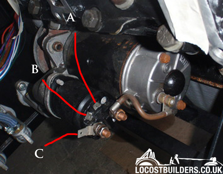
This is a picture of my Rover 3.9l V8's Starter Motor. I am starting to get to grips with my wiring and I don't know which connection
goes where. Can some people label it up for me
|
|
|
|
|
scudderfish
|
| posted on 14/6/11 at 01:24 PM |
|
|
Is there continuity between A & B? If so, A & B are start and a feed to a ballasted coil, C is the mahoosive cable to the battery.
Regards,
Dave
|
|
|
wilkingj
|
| posted on 14/6/11 at 01:31 PM |
|
|
C is a VERY thick cable of at least 2-300 Amps capacity to the Main Battery post as it carries the main starter current when cranking the engine. (You
can also use that spade terminal there as a feed into the loom, but remember its not fused and has full battery current available, namely feed
anything off this terminal through a suitable fuse or to the unswitched portion of the fuse box).
Do NOT use the spade terminal as the main feed to the battery, its a 2-300 AMP cable with Ring Tag job and needs to be properly crimped as well.
Now as for A and B....
I am not sure which is which.
However, One will fire the Starter motor when +12V is applied. (ie form the Ign Swich Start position)
The starter terminal will show a resistance down to ground/earth, as its the solenoid coil you are looking at circuit wise. Probably a fairly low
resistance.
The other will OUTput +12v, and goes to the LT side of the Coil when the engine is cranked.
A quick test with a Ohm Meter will show one this terminal as open circuit or not connected to 12v or to geround. (as its is only connected when
cranking the engine)
BE Warned... This is for the use with a Ballast resistor and Basllast resistor type coil.
IF you have a Ballast resistor coil, then this goes to the LT / Feed side of the coil and puts the 12v direct onto the coil when you are cranking the
engine over.
IF you do NOT have a Ballast resistor and ballast resistor type coil, then you DO NOT need to use the additional 12v output terminal.
Finally make Sure you have a GOOD earth strap (capable of 2-300 Amps) from the Engine to the Chassis. And another (again 2-300 Amps capacity) from the
-Ve battery Terminal to the Chassis.
Failure to have the correct sized Cables will result in Melted cables at the minimum, or a fire damaged car (and even the loss of the garage) if it
all goes pear shaped.
ie Check, CHECK then CHECK AGAIN. Get this right FIRST TIME..
Sorry if I seem a bit on edge... I would hate to see a car go up in flames.
For the IVA (well mine was SVA'd) I think you will need rubber boots over ALL the Live termainals. so put them on BEFORE you crimp on the ring
tags etc. Its a lot easier.

1. The point of a journey is not to arrive.
2. Never take life seriously. Nobody gets out alive anyway.
Best Regards
Geoff
http://www.v8viento.co.uk
|
|
|
wilkingj
|
| posted on 14/6/11 at 01:39 PM |
|
|
quote:
Originally posted by scudderfish
Is there continuity between A & B? If so, A & B are start and a feed to a ballasted coil, C is the mahoosive cable to the battery.
Regards,
Dave
There may not be necessarily be continuity between A and B, as some are a switched contact that operates when the soleniod is fired.
See my explanation how to check which is which. They could be just connected, in whihc case it doesnt matter whihc is which!
Agree re the Mahoosive cable on C 
Cheers
Geoff
1. The point of a journey is not to arrive.
2. Never take life seriously. Nobody gets out alive anyway.
Best Regards
Geoff
http://www.v8viento.co.uk
|
|
|
Irony
|
| posted on 14/6/11 at 08:40 PM |
|
|
So C is the main +ve lead to the battery. I have bought some 25mm square tinned cable which I was told will be okay, Both for the Earths and for the
+ve. Does this need to be thicker?
I don't think I need a ballast resistor as I am going MegaJolt. According to Autosport labs it should be wired as so
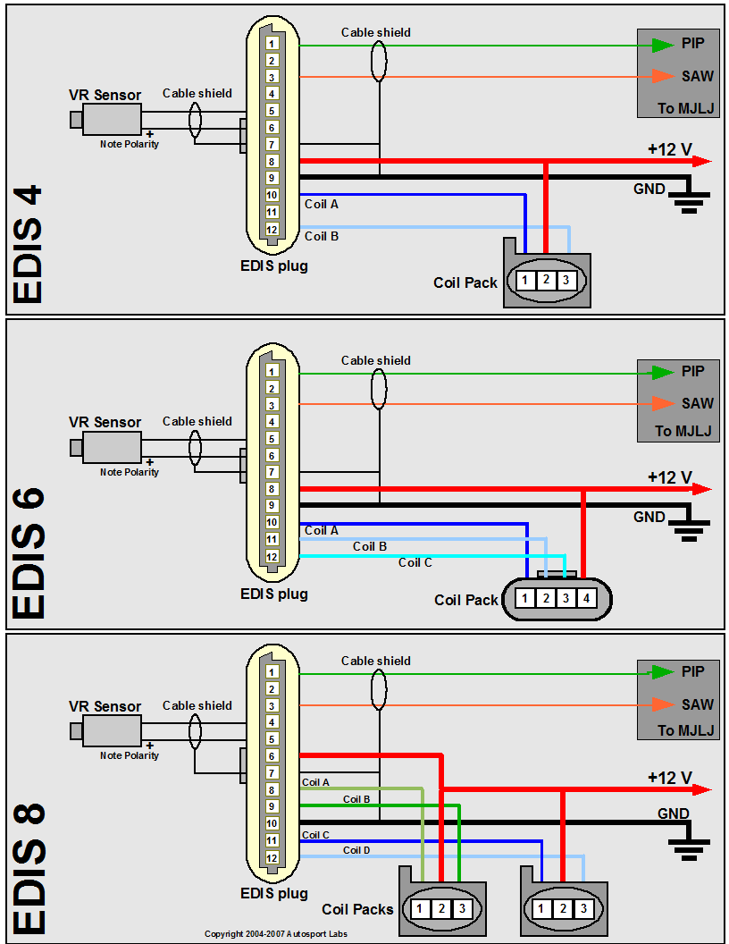
Oh thats a big image sorry.
I have just been out to the garage and put the multimeter on the terminals. There is continuity between B and the big thick brown lead that goes to
the starter. Its late and I can't wrap my head around what that means.
So please correct me if I am wrong, on the Edis 8 diagram above the +ve connection goes to one of the connections on the starter (either A or B) and
the connection thats left plugs into the large ignition switch cable on the loom. This the distributes the +ve around the cars wiring loom etc?
Its seems to me that some car builders run away from electrics in their cars but I am determind to learn as much as I can
Cheers for the replies
|
|
|
scudderfish
|
| posted on 14/6/11 at 08:52 PM |
|
|
The MJ needs no connection to anything to do with the starter. You also don't need to worry about a ballast resistor as you are not running a
coil/dizzy setup. The +12v feed to the EDIS and coils just needs to be a bog standard switched feed that is live when the engine is cranking. There
is probably a fuse in there as well, but I can't remember what.
Regards,
Dave
ETA The feed to A (or B  ) is from your ignition switch/starter button. It is only live when you want the starter to run. Think of it like a relay
that is switching the 300amp feed into the starter motor. ) is from your ignition switch/starter button. It is only live when you want the starter to run. Think of it like a relay
that is switching the 300amp feed into the starter motor.
[Edited on 14/6/11 by scudderfish]
|
|
|
craig1410
|
| posted on 14/6/11 at 09:31 PM |
|
|
I agree with most of the above. Here is a summary to clarify:
C - The spade connection is designed to go to the alternator which is normally situated above and slightly forward of the starter motor and is
therefore in a convenient place to run a short run of thick brown wire between them and then using the starter feed cable back to the battery. As
someone else said, DO NOT connect the battery using the spade connector as there is a risk of it coming off and a spade does not have the same current
capacity as a similar sized ring connector.
B - This is indeed connected to the starter motor feed wire and therefore is at battery voltage (somewhere between 9V and 12V) during cranking. As has
already been said, this feed bypasses the ballast resistor during cranking. The reason for this is because the RV8 ignition coil is designed for 9V
typically and the ballast resistor drops the 12V from the battery down to 9V under normal engine running conditions. However, during cranking, the
battery voltage is already reduced due to the load to around 9V so the ballast resistor must be bypassed to maintain a strong spark at the spark
plugs.
A - Is the feed from ignition key "start" position to the solenoid. Note that on my RV8 (1977 SD1 vintage) it has an additional relay
between the ignition switch and the starter solenoid. I presume this is because the solenoid takes more current than the ignition switch can reliably
handle long term so maybe wise to do the same. Relays are cheaper than ignition switches. Note that this connection is also used to feed the oil
switch and fuel pump relay. The way this works is a bit like a logic "OR" gate. If the ignition is in "start" position
"OR" the oil pressure switch is pressurised then allow the fuel pump to run. This oil pressure switch (if fitted to your engine) has 3
spade connector and is mounted just above the oil pressure sender unit on the right hand side of the engine.
I hope this helps,
Craig.
ps. I have a full electrical schematic for the Rover SD1 3500 if anyone wants a scanned copy.
[Edited on 14/6/2011 by craig1410]
|
|
|
Irony
|
| posted on 15/6/11 at 12:34 PM |
|
|
Thanks for the replies guys - your patience is muchly appreciated
Scudderfish
There are three connections on each of the Ford Coil packs and three outputs on the EDIS 8 for each coil. Seems simple enough. I was thinking though
that the EDIS8 would need its own separate 12+ve supply as I thought it would require a lot of ampage to power the coils. I assume this would come
from the starter and therefor straight from the battery. But your saying the EDIS 8 can just be plumbed into the bog standard switched ignition +ve.
How much ampage would the EDIS and coils use then? I thought it would be a fair bit.
Like Craig said it could be a separate circuit with a relay however.
Craig
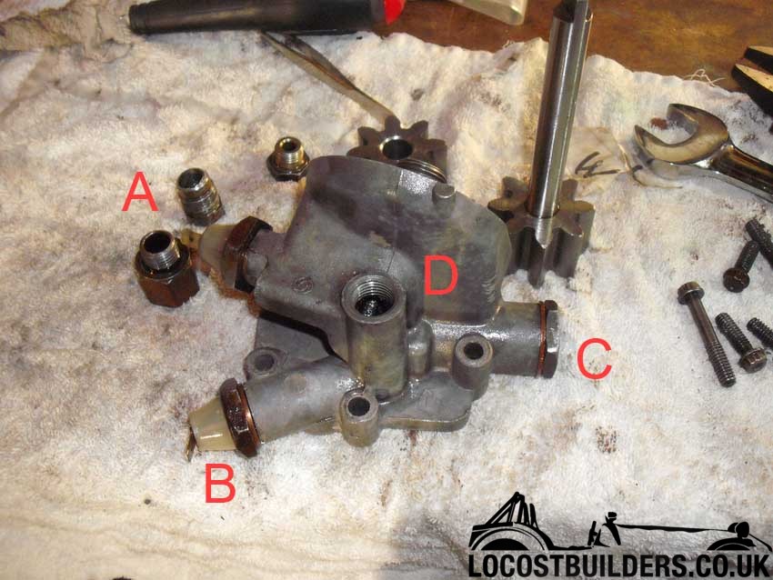
Thanks for this detailed post- its clear most things up for me. I don't think I have a oil pressure switch. My oil pump looks like this
|
|
|
scudderfish
|
| posted on 15/6/11 at 12:51 PM |
|
|
Coils don't need a lot of amps, the spark they generate is just high voltage, not high amps. Certainly no where near what the starter motor
draws.
http://www.autosportlabs.org/viewtopic.php?p=7100&sid=0f7ad7f014fd9274c6f0f283ec2a1fa2
[Edited on 15/6/11 by scudderfish]
|
|
|
craig1410
|
| posted on 15/6/11 at 12:56 PM |
|
|
Not sure about coil-packs but a single coil as used on my RV8 will take about 6 amps when running but can peak at over 10 amps when the ignition is on
but engine not running. I'd recommend a relay between ignition switch and coils.
|
|
|