BigFaceDave
|
| posted on 17/7/11 at 12:07 PM |

|
|
Cosworth cooling
Afternoon all,
Im after a bit of help trying to work out what needs to go where on my cosworth yb engine, I have worked some of it out but I really need a bit of
help with the rest. You can see in the diagram how far I have got so far, Please feel free to correct me if I have done anything wrong.
Also those of you that are familiar with these engines may notice that the 2 outlets on the top left side of the engine are actually off the
thermostat housing but lets just say drawing is not my strong point 
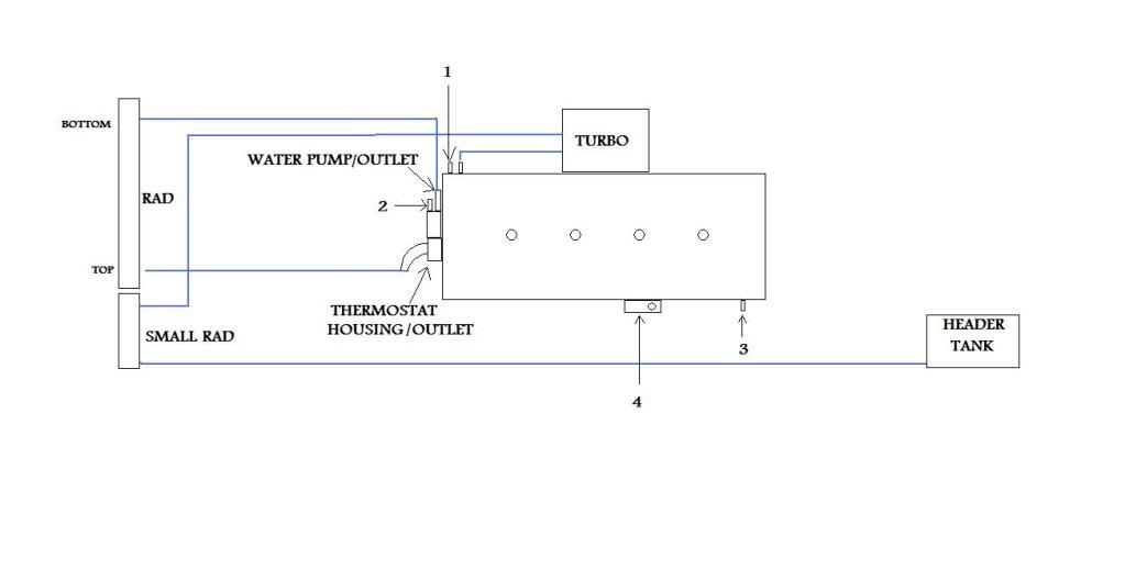
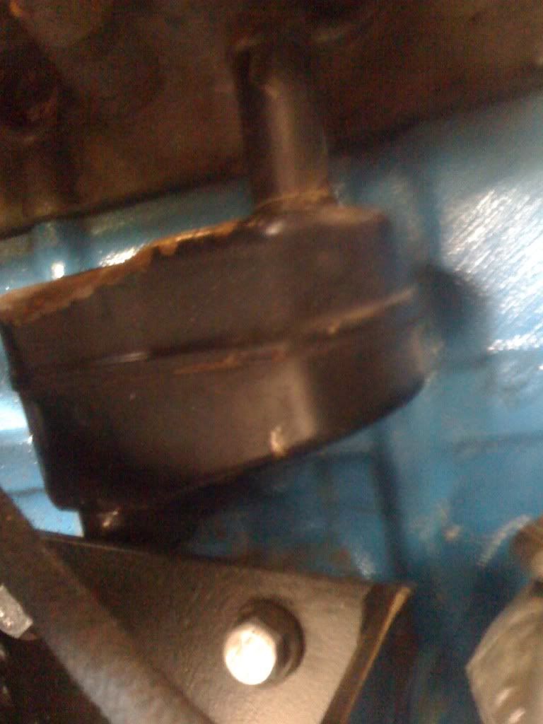
at the minute 1 & 2 are blanked off 3 isnt and 4 is something slightly different which im not sure what it is,I am hoping that the LCB fountain of
knowledge will enlighten me! Here is a picture of it
Thanks.
|
|
|
|
|
jollygreengiant
|
| posted on 13/8/11 at 08:14 AM |
|
|
Sorry been its hectic past few days, just tried finding coolant diagrams but no joy. For my cooling I used a rover 214 header tank (with mounting
frame) plumbed into 'T' in the bottom hose (From water pump to botom of radiator which is from a VW polo). Top hose from thermostat to top
of Rad. Bleed hose from top of rad goes to top of header tank (collecting any other bleed hoses with 'T' pieces. The small coolant pipe
under inlet manifold just connects straight to the small inlet pipe at the water pump (this would normally route through the interior heater matrix)
and this will now cater for coolant circulation until the thermostat opens. The radiator has a fitting for a thermo switch for a cooling fan which can
be mounted on the front or rear of the rad depending on space available. hope this helps.
I must admit I'm not sure on which pipes do what on the YB set up, the man I suspect that you would be best speaking to on this would be Hicost
who is running a very successfull 'YB' turbo with water injection as well. If you 'U2U' him I'm sure he would point you
in the right direction.
I would suspect that the turbo and engine need to be running through the same radiator, but as I said above I not sure, I would also suspect that the
turbo is cooled by water drawn off the inlet side of the block, through the turbo and then into the water pump. The second small water pump pipe would
also connect to the second pipe on the inlet side of the engine. It is always a good Idea to have these connected rather than blocked off as these
allow for engine cooling during warm up and help to stop localised heat stress.
As I said earlier, the best person to speak to would be Hicost, just U2U him and I'm sure he will oblige, he's always been polite, helpful
and courteous in the past. Just search Hicost.
Hope this helps.
JGG
edit bit : I think 4 is crankcase breather.
[Edited on 13/8/11 by jollygreengiant]
Beware of the Goldfish in the tulip mines. The ONLY defence against them is smoking peanut butter sandwiches.
|
|
|
BigFaceDave
|
| posted on 13/8/11 at 08:43 AM |
|
|
Thanks for the help Clive I did ask on the passion ford forum in the week and got the following answer
[img]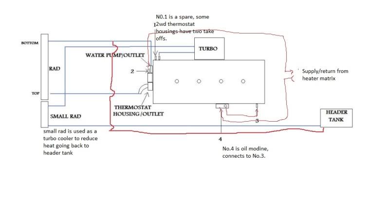 [/img] [/img]
Only because im not using the heater matrix ive been advised to connect 2 to 3 to keep good water flow
and 4 is a oil breather I thought it was but wanted someone who knew what they where talking about to confirm it!
I spoke to a guy a little while ago with a cosworth yb in a robin hood and and he gave me the idea for the little radiator as thats what he has done
on his its basically just inline from the turbo to the header tank so hopefully that will work well!
On a slight side note what is the difference between a header tank and a expansion tank? and which do I need?!
Once again thanks for all the help!
[Edited on 13/8/11 by BigFaceDave]
|
|
|
BigFaceDave
|
| posted on 13/8/11 at 08:46 AM |
|
|
Also I didnt get the standard oil cooler with the engine soI have a sandwich plate style take off and dont need the water supply to the oil cooler.
|
|
|
jollygreengiant
|
| posted on 13/8/11 at 12:47 PM |
|
|
Header tank, expansion tank, I think it runs something like this.
Expansion tank - semi sealed system that vents to a bottle, excess coolant bleeds off to the bottle, but is drawn back in when cold. The whole system
is generally run so that the fill point is at the highest point of the whole engine coolant system.
Header tank - Sealed system, where the (usually clear) plastic coolant bottle is mounted just above the maximum coolant level in the engine, this is
(usually) the only fill point and runs a pressure cap (usually in the 13 - 14 PSI range) that also has a pressure vent. The system is filled to the
max level on the bottle, it has a large (usually about 15 - 20mm) feed of the bottom to the bottom hose and a small bore (usually 6 - 10mm) bleed back
hose to the top of the bottle.
Looking at your diagram would think then :-
Top (main) rad to thermostat - YES
Bottom (main) rad to bottom water pump - YES
Water feed (from inlet manifold) to turbo (in/inlet), Turbo (out/outlet) to small rad (top hose/inlet), small rad (bottom hose/outlet) to top of water
pump (usually interior heater matrix connection).
Then find suitable header tank from breakers with cap, as I said I used one from a Rover 200 series which has large outlet and small return, suitable
pressure cap, and usually has a mounting bracket which is easily modified to fit on the scuttle. This can then be fitted with the outlet
'T' pieced into your bottom hose and the small bleed pipe off of the very top of your radiator(s) can then be run back past the engine
(collecting and other bleed points like the top of the thermostat with 'T' pieces) to the header tank.
I hope this all makes sense.
JGG
Beware of the Goldfish in the tulip mines. The ONLY defence against them is smoking peanut butter sandwiches.
|
|
|
quadra
|
| posted on 13/8/11 at 02:07 PM |
|
|
So the bottom picture is an oil breather, commonly referred to as a 'Kidney Box'. This vents the crankcase and on a standard car is
plumbed back into the inlet. Most people run the oulet from this to a separate breather and also consider venting the other side of the block or the
top of the head (or both). There is some good info here about this. http://www.grahamgoode.com/breath
From your water diagram start with the main thermostat outlet this should go to the Radiator inlet, the water flows through the rad and back out to
the block via an input beneath the thermostat housing. The lower rad pipe needs Teeing and the inlet from the header tank plumbing in.
The turbo is fed via one of the small outlet from the thermo stat housing, the water goes through the turbo and normally directly into the header
tank. Some people choose not to run turbo water cooling, but it depends on how much money you have invested in your turbo I suppose. You could plumb a
small radiator in here but the feed pipe is very small 8mm if I remember rightly.
You definately need to create a water circuit using the outlet at the back of the head with one from the front, which would have been the heater
circuit, this allows water to circulate around the head properly.
You don't need eyes to see, you need vision!
|
|
|