plugy1972
|
 posted on 20/4/12 at 06:31 PM posted on 20/4/12 at 06:31 PM |

|
|
Hazzard switch wiring
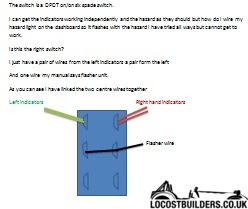
I have change the old style siera toggle switch for a double pole double throw switch(told that is the on i need)
The plasic plug has one flasher wire a pair of wires for the left indicators and a pair for the right indicators.
The toggle switch im trying to wire to is on/of with six spades.
i have attached the flasher to the center left spade 3 and linked across to the other side 4
The indicators are wired together as pairs and are conected 1 left side 2 right side
5 and six have nothing on them.
we flick the swithc and the hazzards function as needed.
flick the swith the other way hazzards stop and the indicators can be used as needed.
BUT we need to wire to the little dash light this has two pins and needs to illuminate and flash when hazzards on but cannot get to work tried all
arangements any input would be greatly appreciated
1 2
3 4
5 6
|
|
|
|
|
YQUSTA
|
| posted on 21/4/12 at 06:47 AM |
|
|
To get the dash light to flash you will need to take your feed from either pin 1 or 2 in your case.
Or from the feeds to your indicators.
HTH
There are a few diagrams in my photo archive that may help you
[Edited on 21/4/12 by YQUSTA]
"If in doubt flat out"
Colin McRae
|
|
|
ReMan
|
| posted on 21/4/12 at 06:49 AM |
|
|
Is your little dash light exclusively forth hazzards or is it the indicator light.
If its exclusive, it ought to be easy enough to tap it from one of the lamp feeds to earth
As ever a wiring diagram paints a thousand words!
Oh and welcome along
www.plusnine.co.uk
|
|
|
snowy2
|
| posted on 21/4/12 at 07:45 AM |
|
|
http://www.andersensmith.freeserve.co.uk/wiringloom6.pdf
it includes an easy (very easy) hazard wiring diagram.....
Dave.
sometimes you are the pigeon, most of the time the statue.
|
|
|
ReMan
|
| posted on 21/4/12 at 08:08 AM |
|
|
quote:
Originally posted by snowy2
http://www.andersensmith.freeserve.co.uk/wiringloom6.pdf
it includes an easy (very easy) hazard wiring diagram.....
Dave.
It would be easier/clearer if it showed the function of the switch...
This sort of thing
http://www.locostbuilders.co.uk/viewthread.php?tid=145580
[Edited on 21/4/12 by ReMan]
www.plusnine.co.uk
|
|
|
plugy1972
|
| posted on 21/4/12 at 09:07 AM |
|
|
hazzard wiring
All is working as should including the two directional lamps flash when hazzourd on, it is the single hazzard warning lamp that i need to get to flash
it just has two spades underneath i have tried allways but cannot get to work
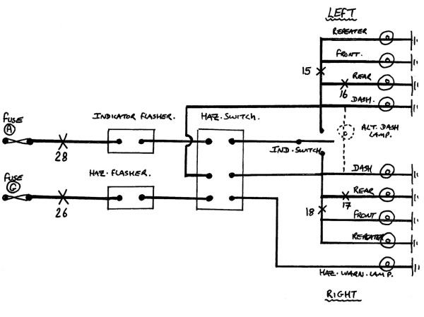
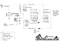
In the diagram posted here it does show a 6 terminal switch as i have got but has two wires one from the hazzard flasher and one from the indicator
flasher i have just got one wire from the loom i assume i use a link wire to join the pins together wire 26 and 28 as illustared in the pic.
Also there is a wire for indicator switch my loom dosnt have that.
All i had was a plastic block with one wire listed as flasher wire, and 2 pairs of wires for the indicators so really just three lots altogether.
The illustation shows
Indicator flasher
Hazard flasher
left lamps
right lamps
indicator switch
hazzard flasher light
Thats six seperate wires as i say i only have 3 can please someone simplify thanks.
|
|
|
snowy2
|
| posted on 21/4/12 at 05:27 PM |
|
|
Essentially your indicators opperate one circuit at a time two indicator bulbs and one warning bulb the hazards do the same but twice over. your
hazard wires just need to connect to both sides of your indicators.
if you look at the PDF file i posted and then look at the hazard diagram you can see that there are 6 wires for the hazards. how much simpler do you
eant it?
[Edited on 21/4/12 by snowy2]
sometimes you are the pigeon, most of the time the statue.
|
|
|
plugy1972
|
| posted on 21/4/12 at 08:52 PM |
|
|
sorry for being a dummy but all the diagrams show
1 flasher wire
1 hazzard flasher wire
and indicator wires.
the loom that had the origanl plastic plus just has a pair of wires for the left and a pair for the right indicators but one flasher wire.
so basically there are three wires 1 flasher 1 lindicator and 1 right indicator.
inicators work as should with the directional light flashing when operated.
throw the switch the hazzards work with the ignition on or of
But i need to wire in a flasher light to operate with hazzard tried all road cannot do it
could i have the wrong switch it is a DPDT on/on switch 6 terminal
|
|
|
ReMan
|
| posted on 21/4/12 at 09:12 PM |
|
|
Perhaps it would be clearer if you post the diagram that you have used/made and we'll recommend where to put the light
www.plusnine.co.uk
|
|
|
plugy1972
|
| posted on 21/4/12 at 10:21 PM |
|
|
have posted a pic sorry for the drawing. http://locostbuilders.co.uk/upload/6pic.jpg
|
|
|
snowy2
|
| posted on 22/4/12 at 06:45 PM |
|
|
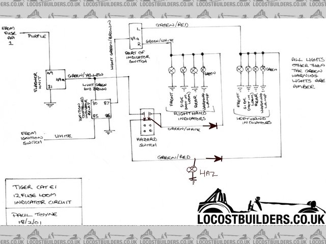
your most basic hazard switch is six connections two are connected when switched off these are for the indicators (a bypass connection) the other four
are connected when the hazards are connected.
basically a wire from the indicator relay goes to one connection on the haz. sw. and the other goes to the indicator switch feed. (2 connections)
the other four are connected all together when the haz.sw, is "on". one to the hazard relay, one to left indicators and one to right
indicators and one to warning lamp (4 connections)
dont mess about with 3 or greater pin indicator relays buy two pin ones they are simpler to use when you dont understand electrics...
[Edited on 22/4/12 by snowy2]
on the drawing above the top two pins of the Haz sw are connected when the hazards are off all the other 4 are connected together when the hazards are
switched on
the alt dash lamp arrangement MUST have the hazard warning lamp as well if you use the separate warning lamps for each direction you dont need to wire
the hazard lamp.....dont hurt to do so though.
[Edited on 23/4/12 by snowy2]
sometimes you are the pigeon, most of the time the statue.
|
|
|
plugy1972
|
| posted on 22/4/12 at 09:21 PM |
|
|
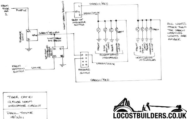
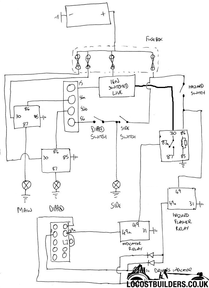
Thanks for the reply here is a better diagram of how the wiring is.
This is how the loom is so looking at the diagram you have it is very differnt.
if i replace the relays it would mean a lot of altering the wiring wounnt it?
Could you show me on the loo i have where to chopo or add wires to make the exsisting loom work please your help is much appreciated.
[Edited on 23/4/12 by plugy1972]
[Edited on 23/4/12 by plugy1972]
|
|
|
ReMan
|
| posted on 22/4/12 at 09:42 PM |
|
|
You may think I'm being pedantic , but we now have 5 diagrams and 3 different switches 6 pin and 8 pin and still no clearer on what they do in
a given state!
This is key to how this circuit operates.
And how the relay with 30 85 86 87 49a etc etc operates?
To understand how this electrifery works is key to the solution
[Edited on 22/4/12 by ReMan]
www.plusnine.co.uk
|
|
|
plugy1972
|
| posted on 22/4/12 at 10:39 PM |
|
|
sorry but have wasted 2 weeks build just because of a poxy switch i had had differnt diagrams but the one i have posted is my loom configuration but
no one has has been able to give me a work around without what looks like like a lot or re wiring.
|
|
|
snowy2
|
| posted on 23/4/12 at 07:29 AM |
|
|
its better if you keep the pictures to about 600-700 pixels so they can be seen with out scrolling,
that said i understand why you have used an ignition controlled relay but the way you have wired it does not lend its self to reliability as the relay
will switch with the indicators considerably shortening its life!
you dont need to use the relay if the power supply is taken from an ignition controlled source. it would be better to use the relay pin 85 to ignition
sw. 86 to earth, 30 to battery 12+ve, 87 to fuse (or fuses as relays are rated at 30A) much better and more reliable.
also do your hazards and indicators work properly as shown in your diagram as you have the right indicators connected via the hazard bypass circuit
and the left to the hazard circuit.......
[Edited on 23/4/12 by snowy2]
sometimes you are the pigeon, most of the time the statue.
|
|
|
snowy2
|
| posted on 23/4/12 at 07:55 AM |
|
|
quote:
Originally posted by plugy1972
I have change the old style siera toggle switch for a double pole double throw switch(told that is the on i need)
The plasic plug has one flasher wire a pair of wires for the left indicators and a pair for the right indicators.
The toggle switch im trying to wire to is on/of with six spades.
i have attached the flasher to the center left spade 3 and linked across to the other side 4
The indicators are wired together as pairs and are conected 1 left side 2 right side
5 and six have nothing on them.
we flick the swithc and the hazzards function as needed.
flick the swith the other way hazzards stop and the indicators can be used as needed.
BUT we need to wire to the little dash light this has two pins and needs to illuminate and flash when hazzards on but cannot get to work tried all
arangements any input would be greatly appreciated
1 2
3 4
5 6
if you are using an LED they will only work with an earth and they must be wired with the correct wire to live, connected the opposite way round it
will never light. with an ordinary bulb it doesn't matter.
if you are using only one bulb for indicators it will NOT also work for hazards for hazards you must always use two indicator warning bulbs with
hazard circuits.... for IVA the hazards can have a separate warning lamp or work both indicator warning bulbs.
Well...... you can use one bulb but you need two diodes as well and if your struggling with this your going to freak with diodes. but if you need to
know.....connect each side of the indicators to ONE of the pins of the warning lamp with diodes and the other pin of the lamp to earth....simples
sometimes you are the pigeon, most of the time the statue.
|
|
|
plugy1972
|
| posted on 23/4/12 at 08:24 AM |
|
|
All works as should hazzards work and indicator directional lights flash.
Flick switch ignition on indictors work with seperate directional lamps.
But i want to wire a hazzard warening light to flash when the hazzard switch is thrown.
You dont mention where the extra wiring is put for the dash hazzard light to flash.
So do i move the wire from pin 87 from the indicator stalks and route to a fuse or leave and connect to it so the wire goes to fuse and indicator
stalk.
Also from what i gather do i get rid of the flasher unit with pins 49a 49 30 on alltogheer?
Still a little confused thank you for the help.
|
|
|
ReMan
|
| posted on 23/4/12 at 08:25 AM |
|
|
You beat me to it.
I don't like that relay being there at all, though how I imagined it would be wired internally I did not think about the possibility of it
flashing, just that it would be permantly powered with the ignition
As the point I was trying to get over to the o/p , you need to understand whats going on inside the relay and the switches with a diagram such as
this
[img]
 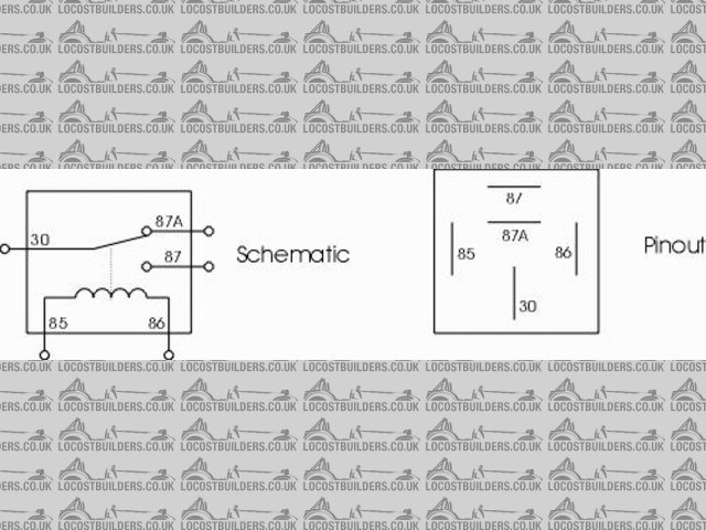
reelay
[/img]
So now having pulled this diagram as you suggest it would switch with the indicators, even worse!
And the way the wires are drawn to the 8 pin? switch look wrong. Again I can imagine what they are supposed to look like, but it's not a good
starting point for someone who is not trained/experienced.
And as you just suggested diodes, in this very bad edit (at work!)
[img]
hazbad
[/img]
would be one way of adapting that.
Again, I hadn't thought that the o/p may be trying to use an led warning light
www.plusnine.co.uk
|
|
|
plugy1972
|
| posted on 23/4/12 at 10:31 AM |
|
|
Ithe plug is the origanl one i am trying to change to a toggle swith
DP/DT on/on
Currently wired as thus.
All wiring the same as in the other diagram but the switch cahnged ]
would this still work how you show as i fell have tried that way.
|
|
|
ReMan
|
| posted on 23/4/12 at 10:41 AM |
|
|
quote:
Originally posted by plugy1972
Ithe plug is the origanl one i am trying to change to a toggle swith
DP/DT on/on
Currently wired as thus.
All wiring the same as in the other diagram but the switch cahnged ]
would this still work how you show as i fell have tried that way.
The switch in this picture is correctly wired as per my markings on the Tiger diagram, so that bit should work
PS try and delete or resize your huge pic off your earlier post
www.plusnine.co.uk
|
|
|
plugy1972
|
| posted on 23/4/12 at 11:16 AM |
|
|
so iam i right in thinking do away with the flasher unit (pin 49 49a 31).
Also the aroows you have drawn are these diods.
Alos the toggle switch is wired slightly differnt than your alterd diagram.
I say again thanks for the help this is not as easy as i thought.
|
|
|
tendoshingan
|
| posted on 23/4/12 at 11:30 AM |
|
|
Well, I can see that a lot of what you're after has been answered already but if this helps too all the better.
I did this as I just wanted the indicator and flasher stalk but not the lights from the sierra, as I was using other switches for those.
I also have a hazard light in the dash connected up to the indicator lights. This comes from the hazard flasher relay 49a then throught the hazard
dash light to earth.
This has been in my car for 3 years and works a treat, no problems so far (touch wood)
|
|
|
plugy1972
|
| posted on 23/4/12 at 12:39 PM |
|
|
with the previous diagram i poted along with the other of the switch.
could someone doctor the diagram to show to to work with a seperate hazzard flasher light.
|
|
|
snowy2
|
| posted on 23/4/12 at 05:49 PM |
|
|
for a separate warning lamp with the hazard switch just connect a bulb to terminal 3 on your switch and earth it, it will flash with the
hazards.......
sometimes you are the pigeon, most of the time the statue.
|
|
|
ReMan
|
| posted on 23/4/12 at 06:04 PM |
|
|
quote:
Originally posted by snowy2
for a separate warning lamp with the hazard switch just connect a bulb to terminal 3 on your switch and earth it, it will flash with the
hazards.......
and the indicators........
www.plusnine.co.uk
|
|
|