FuryRebuild
|
| posted on 29/6/12 at 07:34 PM |

|
|
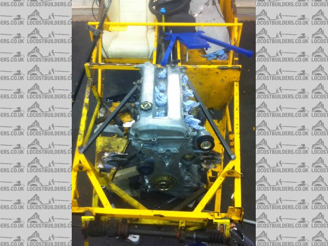
Next chassis strengthening rail is in
So, this is the second strengthening rail in place. Unlike the one on the left which replaces an existing cross member, this one on the right is
entirely new. The original chassis didn't have one of these, so I think this is an improvement. If nothing else, it satisfies my need for
symmetry.
When you look down from the top of the engine, the only thing that would foul a simple extraction of the engine is the starter-motor. Not too tough to
undo that if and when I need the engine out.
I'm out of argon now, so could only seam it in on two sides. I'll get more gas next week - this bottle (BOC, Y Cylinder) didn't seem
to last very long (previous one lasted ages). I need to find another supplier in Harrogate, I think.
My next plan is to fabricate a demountable cross-member that starts from the new front pipe joining areas and goes around the front of the engine,
with 20mm clearance. I don't yet know if I'll weld the tube or bend it. Ideally I'll bend it.
Description
When all you have is a hammer, everything around you is a nail.
www.furyrebuild.co.uk
|
|
|
|
|
tasmod
|
| posted on 30/6/12 at 08:29 AM |
|
|
Next stiffeners. Middle of each new rail down to bottom side rail at an angle, if they wouldn't interfere with anything.
I can't find the link but the Aussies did a lot of work on stiffening like this, as their regs required them to pass a "stiffness
test" during the build. I know it's not a book chassis etc.
Rob
|
|
|
FuryRebuild
|
| posted on 30/6/12 at 08:43 AM |
|
|
Hi Rob
Thanks for the advice - down to the inner or outer side rail?
Looking at this, I might make my strut-brace actually an X instead, and use it to go down to the floor as well as up to the point where all the new
forces meet, in order to provide tortional stiffness near my front mount points.
What's not really visible in that photo is that I have already added a diagonal in the front box-section.
At the back, I'm putting in a roll-over hoop from T45 steel, and it's going to be tied in to plates at the top of the suspension towers,
giving the equivalent of a strut brace there as well.
Finally I'm remaking my wishbones to be off rubber and on to spherical bearings (and oval tube  ) to: ) to:
1) give my new suspension/shocks/etc a good chance of working
2) remove the rod-end-in-bending that's inherent in the design.
I normally wouldn't tackle so many jobs at once, but the chassis is getting recoated and i want to get all the new brackets welded on before I
do so.
When all you have is a hammer, everything around you is a nail.
www.furyrebuild.co.uk
|
|
|
tasmod
|
| posted on 30/6/12 at 09:40 AM |
|
|
I quite understand where you're going with this. Best to do it all at once.
The down tube goes to outer rail.
One of their other successful mods on a locost chassis was X bracing the front. Hard to describe but the actual front behind the radiator.
This along with steering rack mounting strength mods.
They achieved some tremendous results for very little tube. Their method of testing it was simple enough. Fasten chassis down across passenger cell
then fasten a long beam of known length across front. Then hang weights on it to test deflection. Pretty simple description I'm afraid but known
length and weight gives deflection in unit of choice. i.e. pounds or kg.
I've redone my wishbones in oval with rod ends. Then sadness, hillclimb regs ban them on Class 2A, rubber or polybushes only. I had plans to
have another go at Hillclimbing/Sprints next year but that's out now as I would have to lay out too much cash to compete.
I'll try to find the links but i suspect they are all dead now. Maybe some of the forum old timers can remember them.
EDIT: Here ya go. Some good stuff on that site.
http://locost7.info/mirror/aussiemods.php
Some good stuff here as well.
http://www.locostusa.com/forums/viewforum.php?f=39
Chassis drawing
http://locost7.info/files/chassis/aussiemods/framemod.jpg
[Edited on 30-6-12 by tasmod]
Rob
|
|
|
tasmod
|
| posted on 30/6/12 at 09:58 AM |
|
|
Ohh, another thing. Whilst you have the chassis stripped, mark the centre line on the bottom and/or top front and rear rails. Makes string setups
later so much easier.
I centre popped a line on each.
A Fury is the car I would have liked as well as my 7. One day maybe.
[Edited on 30-6-12 by tasmod]
Rob
|
|
|
tasmod
|
| posted on 30/6/12 at 10:09 AM |
|
|
Can't find the link but one of the part time hillclimbers used a bolt in/out frontwards bracing for the roll bar. This he claimed was measurably
stiffer.
Came from centre of the rollbar down to outer edge passenger footwell, furthest in. When he was on his own on road or hillclimbing it was in. When he
took wife out in car he unbolted it. Simples.
Hope there's some good ideas there.
Hmm, that avatar pic. Not an opposite locker at Harewood by any chance?
[Edited on 30-6-12 by tasmod]
Rob
|
|
|
DIY Si
|
| posted on 30/6/12 at 10:20 AM |
|
|
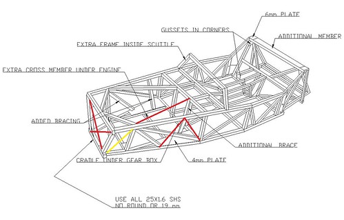
Some of those additional rails in the bottom pic are not ideally placed. In a spaceframe, all tubes should go to a node or joint. Anything that goes
to the centre or otherwise of a rail is not ideal. The engine bay sides could be re-done with little effort, and the second engine bay diagonal you
already have. Should they prove problematic, you can make the straight brace a Y shape at the engine bay rear end. It's not quite as good, but
better than not having one at all. You can see the ones I opted to make back when I was still building:

The tubes in red are fairly straight forward, and should provide an easy benefit. The yellow tube can go the other way if required to clear the rack
or wishbone mounts, depending upon what you have where. There are other things you can do, but with an open cockpit they'll only ever make so
much difference as that's the weakest/bendiest bit of the chassis.
Let your plans be dark and as impenetratable as night, and when you move, fall like a thunderbolt.
Sun Tzu, The Art of War
My new blog: http://spritecave.blogspot.co.uk/
|
|
|
DIY Si
|
| posted on 30/6/12 at 10:22 AM |
|
|
quote:
Originally posted by tasmod
Can't find the link but one of the part time hillclimbers used a bolt in/out frontwards bracing for the roll bar. This he claimed was measurably
stiffer.
Came from centre of the rollbar down to outer edge passenger footwell, furthest in. When he was on his own on road or hillclimbing it was in. When he
took wife out in car he unbolted it. Simples.
Hope there's some good ideas there.
Hmm, that avatar pic. Not an opposite locker at Harewood by any chance?
[Edited on 30-6-12 by tasmod]
Anything linking a nice roll bar to the front of the chassis will make a difference. A full cage is best, being a nice large 3D structure, but I too
have seen folk using a bolt in/out front stay. It's a reasonable compromise between practicality and stiffness.
Let your plans be dark and as impenetratable as night, and when you move, fall like a thunderbolt.
Sun Tzu, The Art of War
My new blog: http://spritecave.blogspot.co.uk/
|
|
|
FuryRebuild
|
| posted on 30/6/12 at 02:33 PM |
|
|
Guys - I'm touched by your efforts - I will study these diagrams with some care and act on them.
I already have the nice long length of T45 to go down from the hoop into the bottom corner of the passenger footwell, and I'm going to make it
demountable. I do want to avoid a full cage if possible - I love the fury lines and want to by sympathetic to them. My spec is track days and hooning
about, so I don't anticipate the kind of splatting I would get racing.
Saying that, the hoop is FSA height and material, cross braced, and will carry two out-riggers to the back of the car. This gets interesting because
I'm moving the petrol tank away from the usual place at the back (too much polar moment of intertia) and putting it in the transmission tunnel.
This now makes all that space around there fairly void and pointless. One option would be to chop the tank hanging structure out and add another loop
of t45 - then i'd have a lovely rear-impact structure as well.
Where you have the red crossing members at the front of the chassis, I have one, and where the steering rack sits on out-riggers, i've
triangulated them down to the chassis. I've also replaced the steering rack bushes with solid.
I also intend to add some riggers underneath the transmission tunnel to make it a box rather than a 'u' shape that it is now.
I understand what you mean about the top braces - this is the way the fury chassis comes. I think my plan for this will be to change my strut brace
plans so in the horizontal plane of the top of the chassis where the rocker arm sits on the triangles that don't meet at a node, I'll
bring another triangle from each node in towards the front of the engine where they will pick up the strut-brace. So looking down from above, you will
see a
___
W
sort of shape, and the strut brace will also triangulate down to the bottom of the chassis, normal to the plane of the W shape on the left.
This means the suspension components are contained in a virtual box of their own. I am tempted to modify the sump and weld a cross-member inside of it
with external bolt attachments - this will give me an opportunity to pass the force straight through the sump from side to side, but has the
disadvantage of solid-mounting the engine. I think one can possibly go too far. If I don't do this, I may make a spider kind of cradle under the
engine to tie the forces in side to side. What do you think? What I want to avoid is adding back all the weight I lost changing engines
I'm keen
When all you have is a hammer, everything around you is a nail.
www.furyrebuild.co.uk
|
|
|
DIY Si
|
| posted on 30/6/12 at 03:15 PM |
|
|
An under engine brace would help, but may prove a right PITA to make and fit in a way that doesn't obstruct anything. Don't bother with
trying to solid mount the sump though, that's a daft idea really!
You've got the idea behind the front mods, to create a nice box that all the forces are fed into. Try and carry that idea around the chassis and
you'll not be far out. As you've figured out though, you can go overboard with these things and beyond a certain point you're just
adding weight.
Let your plans be dark and as impenetratable as night, and when you move, fall like a thunderbolt.
Sun Tzu, The Art of War
My new blog: http://spritecave.blogspot.co.uk/
|
|
|