b14wrc
|
| posted on 7/11/12 at 08:33 PM |

|
|
Weld sections - photos
Hi Guys,
Put this as a new post from the original I posted regarding my welding practice.
http://www.locostbuilders.co.uk/forum/2/viewthread.php?tid=175512
This is my latest effort with my SIP105T. Main problem is lack of penetration but have some fusion now, better than the first one!
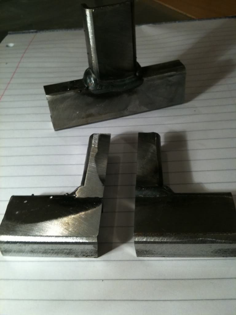
Weld has been acid etched.
Still have a void in the root, nice stress raiser and will be a point for fatigue.....
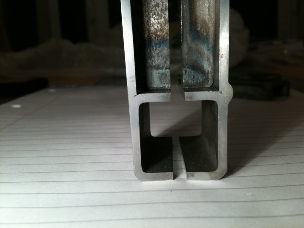
Where the weld is flatted off, you can see penetration went almost 2/3 through.
On the whole from the outside they look ok, but inside, I'm not fully confident.
My conclusion is I need more power. Going to look at up grading my welder. The extra 70amps should help get that root fused!
Thought people might like the info as I am in a lucky position that I work with some very knowledgable guys that are metallurgists and welding
engineers.
Rob
[Edited on 7/11/12 by b14wrc]
20vt powered rear engined locost
|
|
|
|
|
JoelP
|
| posted on 7/11/12 at 08:38 PM |
|
|
No good IMHO, but you probably know that. You need total penetration. Looks like the weld pool is just sat on top of the join in a few of them. Needs
much more amps and a bit less wire feed IMHO. It is said that if you arent having to be careful to avoid blowing holes in the tubes, then you probably
dont have enough ampage - maybe thats a bit OTT, but it shows the point at least.
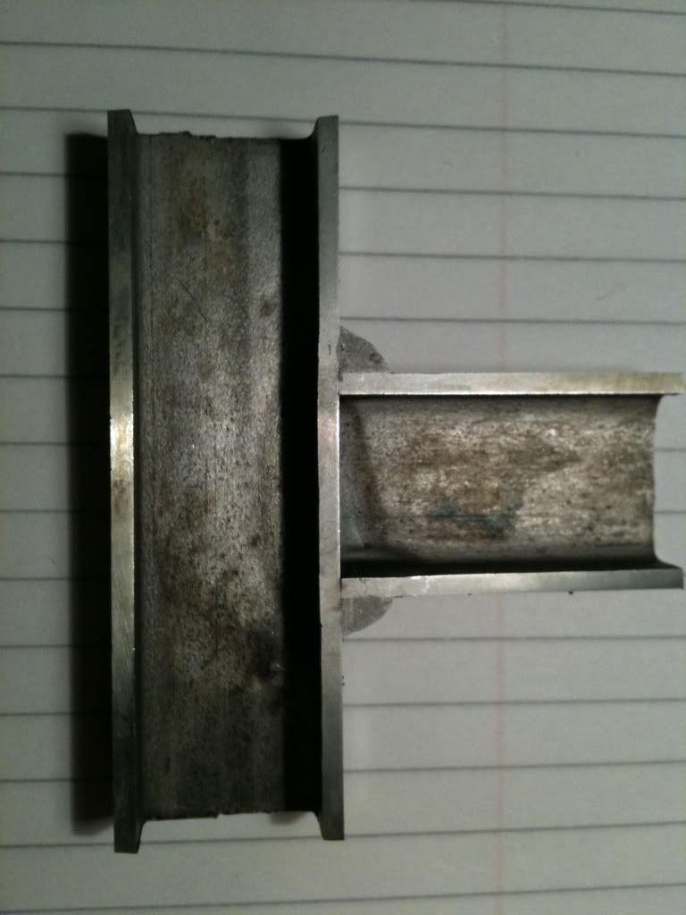
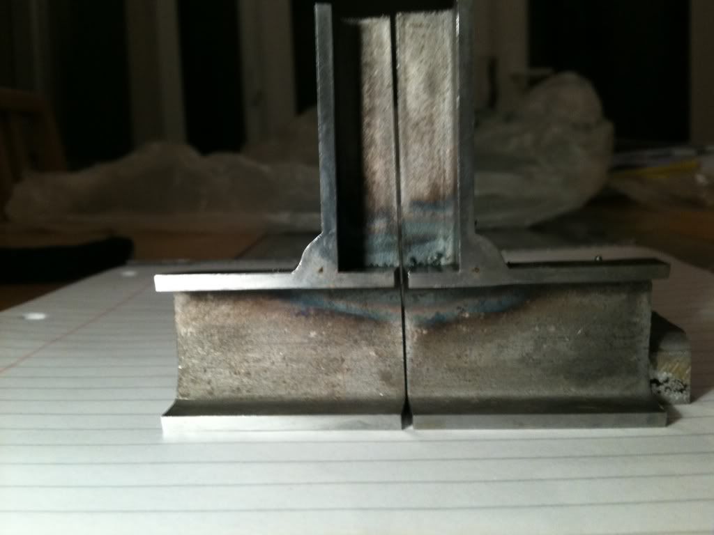
Photo 4, which appears to show best penetration, is probably actually just the fillet filling the gap between the tubes since the lower tube has
rounded shoulders.
I started with a 135amp welder which i dont recall being too under powered. Now have a 160a which is better.
[Edited on 7/11/12 by JoelP]
Beware! Bourettes is binfectious.
|
|
|
Minicooper
|
| posted on 7/11/12 at 08:56 PM |
|
|
The box section your welding is far thicker than you would use on a locost spaceframe, try it on the box section you would actually use, 105 amps
should easily be enough to blow holes in 16swg box section
Cheers
David
|
|
|
johnemms
|
| posted on 7/11/12 at 09:08 PM |
|
|
I'd like to see a 16swg section welded and cut please..
Also prepare and chamfer the edges to be welded as well ..
[Edited on 7/11/12 by johnemms]
Own chassis & Build - First time pass!!
"7's" aren't really "cars", they are 'experiences"
|
|
|
b14wrc
|
| posted on 7/11/12 at 09:50 PM |
|
|
Guys,
That tube is 25mm x 25mm x 2mm wall thickness. It's exactly what I'm using for the chassis!
Why do you think its thicker?
The above tube is what every one recommended I went for about 6months ago.
Rob
20vt powered rear engined locost
|
|
|
Minicooper
|
| posted on 7/11/12 at 09:56 PM |
|
|
It looks really thick or at least it appears to be, 2mm is fine, I've used it myself
Cheers
David
|
|
|
b14wrc
|
| posted on 7/11/12 at 10:08 PM |
|
|
No problem David. Lol.
It does look beefy, I went for 2.0mm over 1.6mm as I am going to be running a lot of power and have a fairly heavy lump. Many people on the club
suggested the 25mm box 2mm wall would be spot on. Got over 110m of steel so a bit late to change my mind. 
Any way, my issue is the 105amp welder isn't penetrating and I've had some tuition with respect to my welding technique so I'm
fairly certain I need more ampage now.
Regards, Rob
20vt powered rear engined locost
|
|
|
se7en
|
| posted on 7/11/12 at 11:03 PM |
|
|
Chamfer the end edges; that will get penetration.
HTH
Tom
|
|
|
blakep82
|
| posted on 7/11/12 at 11:15 PM |
|
|
quote:
Originally posted by se7en
Chamfer the end edges; that will get penetration.
HTH
Tom
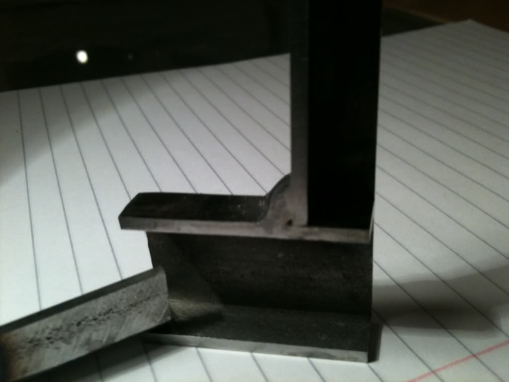
this photo shows a sort of chamfer as the corner of the box is curved, but still not much penetration.
current/voltage up, wire speed down, and slower travel speed imo. could be wrong, but its what i think will work. slower speed will get more heat in
and get it all nicely melted, but with slower travel, you don't want too much wire in as it'll just build up
look forward to more pictures, but as said yes you do really need a small gap/camfer where the flat edges all meet too
what did you cut them with?! its like a perfect smooth cut!
[Edited on 7/11/12 by blakep82]
________________________
IVA manual link http://www.businesslink.gov.uk/bdotg/action/detail?type=RESOURCES&itemId=1081997083
don't write OT on a new thread title, you're creating the topic, everything you write is very much ON topic!
|
|
|
johnemms
|
| posted on 8/11/12 at 07:48 AM |
|
|
Looks like you've played the weld - edge to edge with a lot of cold wire feed.
Concentrate on getting heat into the job/joint get it 'hot & molten'.
When kicking off .. Dont move the gun till you get good heat and penatration.
Looking for a 'pool' molten metal.. with a slightly flat and not convex appearance..
If it fills up before you get good molten metal - then back off the feed..
The wire is just filler ... what wire are you using? 0.6 0.8 1.0 ?
I could be wrong...
[Edited on 8/11/12 by johnemms]
Own chassis & Build - First time pass!!
"7's" aren't really "cars", they are 'experiences"
|
|
|
hughpinder
|
| posted on 8/11/12 at 08:14 AM |
|
|
It does look strangely like there is almost no penetration/fusion - look at the second photo in the original post - the weld bead is quite distinctly
different from the actual tube and just sat on top. Is the gas flow ok? I would also try reducing the wire feed rate, as long as it does not then burn
back too much and weld itself to the tip.
Best of luck
Hugh
|
|
|
40inches
|
| posted on 8/11/12 at 11:34 AM |
|
|
Looks like my first efforts at college, I would say wire feed too fast and/or wire too thick. I found on my MIG 90 that .6 wire
gave far better results than .8 wire.
I would get some off cuts of 2mm sheet and practice welds on that, it is much easier to see the penetration on sheet, I found
that I could blow holes in 2mm easily with 90amps.
|
|
|
The Shootist
|
| posted on 8/11/12 at 03:49 PM |
|
|
Online Tutorial for MIG...
Online MIG Tutorial
Hands down the best reference I have used, with an excellent section on setting power and feed by ear.
|
|
|
ShaunB
|
| posted on 9/11/12 at 01:03 PM |
|
|
What's your earth clamp like? I upgraded the earth cable and clamp whilst overhauling my Sealey 130 and realised it had been limiting the
current when I started using it again.
|
|
|
b14wrc
|
| posted on 9/11/12 at 02:38 PM |
|
|
Earth clamp is fine. I clamped it directly to the piece as well so only a small distance to go.
The welder is in good condition. Going to sell it and get a bigger unit.
When people say better "results", what do they mean? Did you actually see the weld on the reverse side penetrate through at the filet? Did
you blow holes in the filet area because your 100a machine was too hot? No way will mine blow a hole in the filet.
Had it at work and two pros used it and another friend of mine who is a welding engineer came around to see what my technique was like, he said it
seemed ok - but still not even half penetration.....
Any one cut their welds open? People that are using the lower powered machines?
Rob
20vt powered rear engined locost
|
|
|
Slimy38
|
| posted on 9/11/12 at 02:55 PM |
|
|
When I did my C&G welding, they cut the welds through with a bandsaw and then applied something to make it obvious (is that the etching you
mentioned?). For the good welds, you could see that 'something' had happened to the metal about the same distance in as the weld was on
top. I'm probably not describing myself very well, this page is better;
http://www.mig-welding.co.uk/wiki/Macro_Etch
Those pictures show how far the weld can/should penetrate.
With regards to blow through, I did find when the torch was set at a 'good' setting it was possible to blow through if I paused for too
long, I definitely had to keep things moving. Even without blow through I could see the metal discolour on the back. I also had to 'speed
up' on long welds as the whole piece of metal started to warm up and it was getting easier to blow through.
Forgive my poor descriptions, that C&G course was my first attempt at welding, and I've used maybe a metre or two of welding wire since then
(about 3 years ago!). I'm definitely doing everything from vague memory!
[Edited on 9/11/12 by Slimy38]
|
|
|
b14wrc
|
| posted on 9/11/12 at 03:27 PM |
|
|
Yes that link shows what we did. At work I looked at them under a micro scope and it was very clear the penetration had not reached the root.
I was not in danger of blowing through on mine, even at very low travel speeds, only built up weld which sat on the top of the parent material.
Cheers, Rob
20vt powered rear engined locost
|
|
|
MikeRJ
|
| posted on 9/11/12 at 03:48 PM |
|
|
quote:
Originally posted by b14wrc
Guys,
That tube is 25mm x 25mm x 2mm wall thickness. It's exactly what I'm using for the chassis!
Why do you think its thicker?
It does looks quite a bit thicker than 2mm if it's 25mm box. I've just put the picture into photo editor and measured the wall thickness
vs the total width in pixels, and it comes out to 2.5mm, which is a common size. Have you actually had a vernier on the wall to make sure
you've been sold the correct stuff?
|
|
|
Minicooper
|
| posted on 9/11/12 at 04:21 PM |
|
|
quote:
Originally posted by MikeRJ
quote:
Originally posted by b14wrc
Guys,
That tube is 25mm x 25mm x 2mm wall thickness. It's exactly what I'm using for the chassis!
Why do you think its thicker?
It does looks quite a bit thicker than 2mm if it's 25mm box. I've just put the picture into photo editor and measured the wall thickness
vs the total width in pixels, and it comes out to 2.5mm, which is a common size. Have you actually had a vernier on the wall to make sure
you've been sold the correct stuff?
I came to that conclusion by scaling it from the screen, worth checking, hopefully is just the burr and is the correct thickness
Cheers
David
|
|
|
iank
|
| posted on 9/11/12 at 05:55 PM |
|
|
You say the earth clamp is fine, but if it's the one that comes with the welder then it's on the weedy side. Upgrades to 200A or even
400A clamps help a surprising amount on small machines.
Is the 105T a gas/gasless machine? If so have you checked the polarity?
--
Never argue with an idiot. They drag you down to their level, then beat you with experience.
Anonymous
|
|
|
b14wrc
|
| posted on 9/11/12 at 07:26 PM |
|
|
It's a SIP 105turbo, doesn't do gasless so polarity can't be switched. The earth strap is wired in so I can't change it.
I measured the box with a steel rule and it was 2.00mm as far as I could see. I will recheck when I'm next home. I also have some round tube
which is 33 o/d and wall thickness of 2.5mm, that is thicker.
Settings wise:
I'm running soild 0.8 wire
Gas is Argon mix at a pressure of 10l/min
I am using the max temp setting
On around a medium wire feed rate
My mate Dan is a welding engineer and helped dial in the settings last Friday. We played around a bit on scrap prior to making this. I made two
exactly the same. The other one was put in the vice and I braid hell out of it with a large hammer! Resulting in some pretty bent tube! So welds hold,
but as you can see internally they arn't as good as they could be.
I actually think appearance wise they look quite neat.
Rob
20vt powered rear engined locost
|
|
|
MikeRJ
|
| posted on 10/11/12 at 03:38 PM |
|
|
quote:
Originally posted by iank
You say the earth clamp is fine, but if it's the one that comes with the welder then it's on the weedy side. Upgrades to 200A or even
400A clamps help a surprising amount on small machines.
Fitting a proper heavy duty earth cable and clamp onto my Clarke MIG absolutely transformed it. The original looks like a bit of damp string with a
bent paper clip on the end by comparison.
|
|
|
b14wrc
|
| posted on 19/11/12 at 09:05 PM |
|
|
Hi all,
Ok, so back in Cumbria since I was away working last week. Been to BOC and taken the plunge to upgrade:
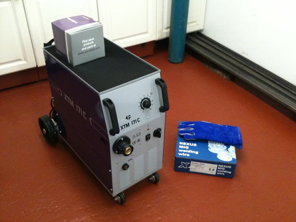
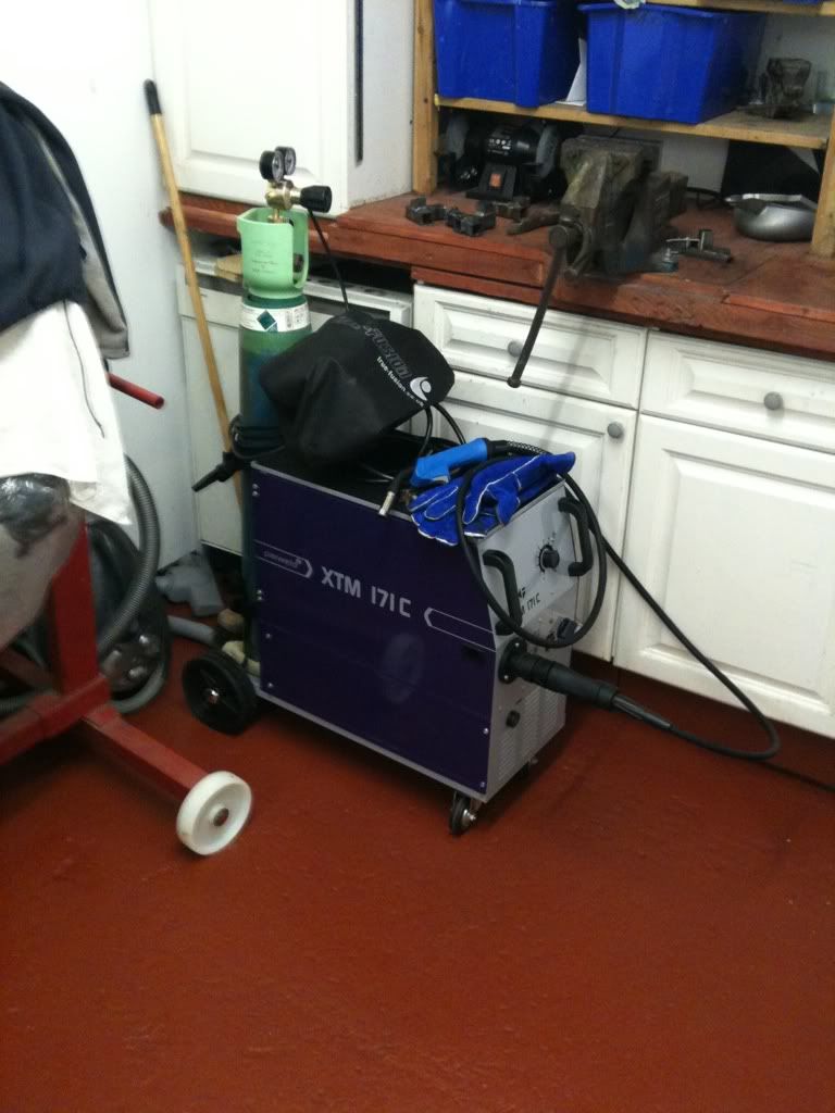
First impression is this is an awesome welding machine, I have not really played with the setting too much yet, but I'm much improved over my
last efforts. Seems a lot easier to use too. Made up another T section so hopefully at work tomorrow I will find out if I can start building next
week. Very exciting!
Sold my SIP 105, that should be getting collected on Friday. 
By the way, measured my box section with some verniers and the thickness is 2.36mm to 2.45mm, nominally this is sold as 2.0mm but guess the tolerances
are not that tight. Not bothered. Means it will be a touch heavier than I'd designed.
Rob
20vt powered rear engined locost
|
|
|