Thanks for the cooling fan relay info I've never got as far as looking into this. I've always run a direct switch from the rad or top
hose. Have you had if upto temperature and checked the operation.
My project ......had to make the exhaust so I can finalise the cooling plumbing. ...ignition "on" and cooling relay next to battery...all
other fuses and relays on other side of engine bay.
sometimes you are the pigeon, most of the time the statue.
Would the blacktop pinout work for a LAAN mondeo ecu for my sierra
quote:Originally posted by big_wasa
WARNING I WILL NOT BE HELD RESPONSIBLE FOR ANY LOSSES OR INJURY RESULTING FROM USE OF THE INFORMATION CONTAINED WITHIN THIS POST.
As this is locost builders there are some people left that love to tinker and make things.
This is to give those people that are interested in running a ford efi engine on a budget a little more info on how the Immobilizer can be used out of
the donor car.
The key to using the the ecu is the Pat's immobilizer. You must get atleast one key with chip that is matched to the ecu.
You can not bypass it but you can use it.
Silver Top
The following pinouts are ONLY for the ecu with the code OWLS but with the info you can often work out other ecu's
Ford 104 pin Mondeo 1997 owls ecu plug.
Missing numbers have no connection and are not used on the owls ecu or the function has not been found. This is still under development.
Pin number -- colour -- function.
08 yellow/green -- Pats
13 white/blue--Data Link connector.
15 blue-- Data Link connector.
16 grey-- Data Link connector.
19 grey/orange -- Pats TX signal.
20 black/blue -- Injector 3 switched earth.
21 white/red -- crankshaft position sensor +.
22 brown/rd --crankshaft position sensor -.
24 black/yellow -- ground
25 black/red -- ground separate earth @ ecu plug.
26 brown/blue -- switched earth coil 1 (pin 1 on coil).
27 black/yellow starter relay inhibiter
30 white/black -- octane plug
36 brown/blue -- MAF.
38 white/green -- Engine coolant temp sensor.
39 white violet -- Air temp sensor.
40 violet/black -- fuel pump monitor.
42 black/blue -- PATS Led.
48 white -- Tacho.
51 black/yellow -- ground.
52 brown/blue -- switched ground coil 2 (pin 3 on coil)
53 white/green -- Pats RX signal.
54 black/blue -- fuel pump switched earth.
55 orange/yellow Pin 10 c2513 KAM perm live.
60 white -- HO2S 1 signal
70 black/white -- injector 1 switched earth.
71 green/yellow -- switched 12v from power relay.
76 brown/white -- Cam position sensor.
77 black/yellow -- ground.
83 green/yellow -- idle air control valve.
85 white violet -- camshaft position sensor.
88 white/blue -- MAF.
89 white -- throttle position sensor.
90 yellow -- 5v Voltage Reference (tps)
91 brown -- sensor common.
93 black/yellow -- HO2S 1 control (earth).
95 black/orange -- injector 4 switched earth.
96 black/yellow -- injector 2 switched earth.
97 green/yellow -- switched 12v.
103 black/yellow -- earth.
Black Top
Ford 104 pin Mondeo 1999 owl5 Pcm plug. C401.
Pin number -- colour -- function.
13 white/blue--Data Link connector.
15 blue-- Data Link connector.
16 grey-- Data Link connector.
17 black/white -- to PIN 25 on c2513.
19 grey/orange -- to Pin 32 on c2513 Pats TX signal.
20 black/blue -- Injector 3 switched earth.
21 white/red -- crankshaft position sensor +.
22 brown/rd --crankshaft position sensor -.
24 black/yellow -- ground pin 9 on c2513.
25 black/red -- ground separate earth @ Pcm plug.
26 black/blue -- switched earth coil 1 (pin 1 on coil).
27 black/yellow -- pin 36 on square c2513 start inhibit relay circuit. ???
28 white/violet -- pin 13 on c2513 vehicle speed signal ( split to Pcm and dash).
31 white -- pin 7 on c2513 Power steering pressure switch. ???
36 brown/blue -- Pin 4 on square c2513 MAF return.
38 white/green -- coolant temp sensor (P1 mini timer)
39 white violet -- Air temp in MAF (P1 Maf plug)
40 violet/black -- Pin 19 c2513 fuel pump monitor.
41 violet/blue -- Pin 23 c2513 A/C clutch pressure switch.???
42 black/blue -- Pin 6 c2513 PATS Led. ???
43 white -- Pin 28 on c2513 sensor signal white. ???
47 black/green -- vacuum solenoid valve control (pin 2 small plug).
48 white -- Pin 30 on c2513 Tacho.
51 black/yellow -- Pin 9 on c2513 ground.
52 brown/blue -- switched ground coil 2 (pin 3 on coil)
53 white/green -- Pin 35 on c2513 s Pats RX signal.
54 black/blue -- Pin 5 on c2513 fuel pump switched earth.
55 orange/yellow Pin 10 c2513 KAM perm live.
58 white/blue -- Pin 2 on c2513 Vehicle speed Sensor.
59 white/green -- Alternator monitor circuit (Pin 2 on alt plug)
60 white -- HO2S 1 signal
64 white -- Pin 39 c2513 clutch switch.???
65 white/green -- exhaust pressure transducer signal(large plug )
67 black/orange -- Pin 18 c2513EVAP canister vent control . ???
68 black/blue -- Pin 20 c2513 switched ground black/blue ???
69 black/yellow -- Pin 27 c2513 switched ground. ???
70 black/white -- injector 1 switched earth.
71 green/yellow -- switched 12v from power relay.
76 brown/white -- Cam position sensor.
77 black/yellow -- Pin 9 c2513 earth.
83 green/yellow -- idle air control valve (pin 2).
85 white violet -- camshaft position sensor.
86 black/blue -- Pin 40 c2513. ???
88 white/blue -- MAF output.
89 white -- throttle position sensor (pin 2)
90 yellow -- 5v Voltage Reference (5v out from ecu)
91 brown -- Pin 38 c2513 + sensor common brown
93 black/yellow -- HO2S 1 control.
95 black/orange -- injector 4 switched earth.
96 black/yellow -- injector 2 switched earth.
97 green/yellow -- Pin 1 c2513 switched 12v.
103 black/yellow -- Pin 9 c2513 earth.
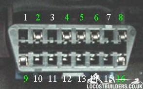
DLC Diagnostic link connector.
The obd2 plug is found under the steering wheel. The plastic body should be unclipped from its holder and cut from the Mondeo with as much wire as can
be pulled free.
The tape covering the wires can be removed.
You will be left with This.
The pins are numbered as below.
Not all pins are used.
Pin outs of the Dlc plug, these go to your harness plug.
2) To pin 16 (grey) on ecu plug.
4) To earth (Chassis).
5) To earth (chassis).
7) To pin 13 (white/blue) on ecu plug.
10) To pin 15 (blue) on ecu plug.
16) To switched 12v fuse box.
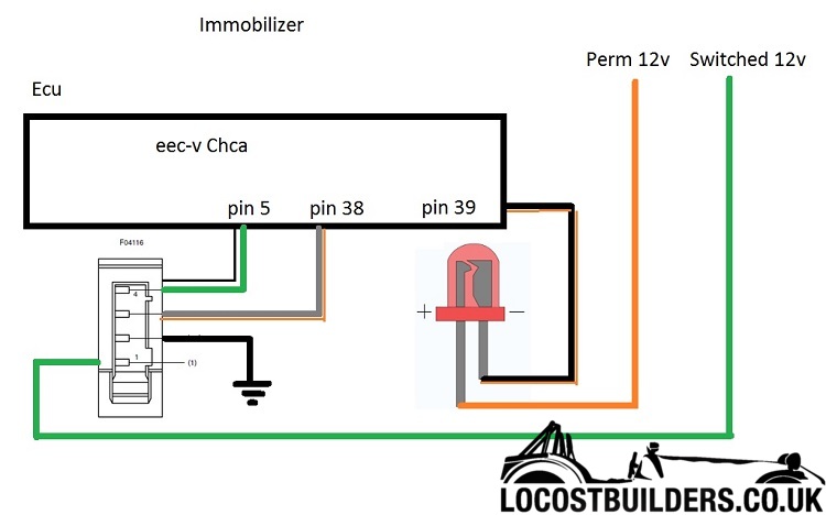
Pats indicator. This is the led that is usually found in the clock of the Mondeo. Its job is to show you the status of the immobilizer. Fords Passive
Anti- Theft- System ( PATS )
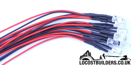
Just one Pin from the ecu plug, No 42 (black/blue). This is a switched earth. Take one Led, colour of your choice. You need one that is pre wired
with a resistor. This is mounted in your dash. The negative or black wire is connected to pin 42 of the ecu plug and the red or positive wire is
connected to the permanent live.
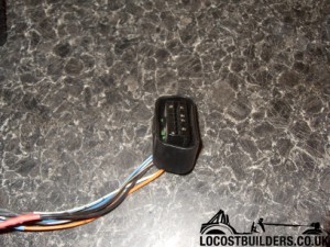
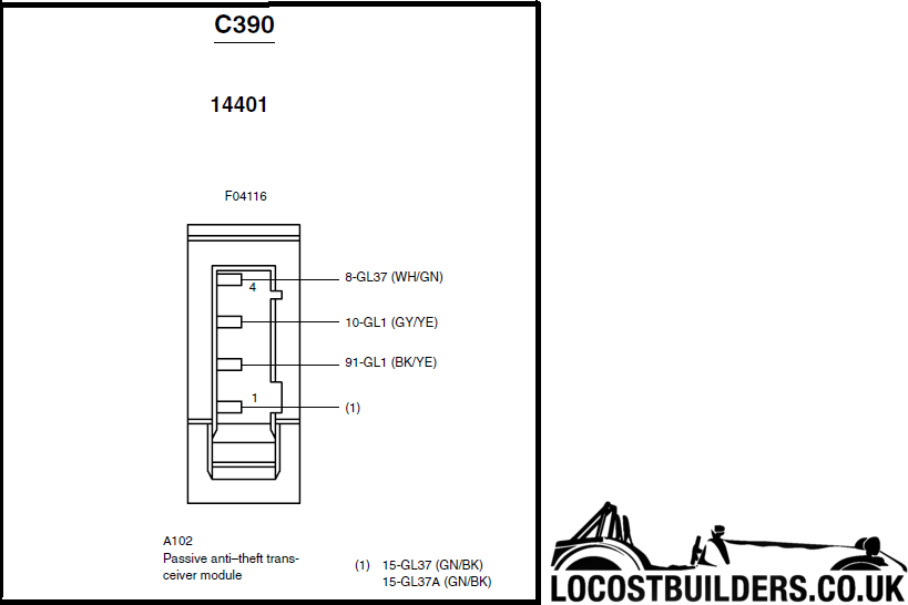
The Immobilizer.
The picture below shows the transceiver or aerial. This is found behind the steering cowl. The ring sits around the ignition switch and is held to
the steering column with one screw.
This is the wiring plug.
It needs cutting from the car with as much wire as can be pulled free.
Retaining clip shown at the bottom.
There are four pins, They may be colour coded as above or they may be all black as shown in the photo. This depends on the age of the donor.
Pin 3 to pin 19 grey/orange -- Pats TX signal.
Pin 4 to pin 53 white/green -- Pats RX signal.
Pin 2 is the earth, to chassis.
Pin 1 is a switched 12v.
All four wires will need extending from the harness plug up to the steering column.
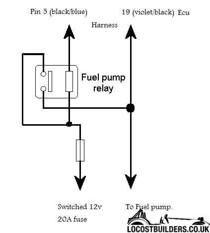
Fuel pump relay.
The Ecu, both controls and monitors the fuel pump via a relay.
There are two pins from the ecu plug.
Pin 54 (black/blue) from ecu plug, Fuel pump relay control switched earth.
Pin 40 (violet/black) from ecu plug, fuel pump monitor.
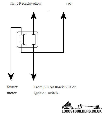
Starter motor inhibitor relay. This stops the engine from cranking as part of the immobilizer.
Pin 27 (black/yellow) ecu plug -- starter motor relay control (switched earth).
Hope this helps any one wanting to run a zetec without spending shed loads. Its no harder than making a loom for a MS ecu. There is no mapping and the
ecu can be had for a few quid.
Just a quick note to say thank so much to Big Wasa - this work has been completely invaluable when wiring up the ST engine in my Westie - I simply
could not have done it without the info you've posted so cheers!
Right ive done the above pinout on my ecu and it won't start. Ive got the pats led flashing all the time and just turns over so i have code read
it today and got the following
1.) p1000 not all obd11 complete
2.) p0230 fuel pump circuit malfunction
3.) p1633 keep alive power too low
4.) b1600 passive anti theft system key transponder signal not receved
So the Laan is from a 2.0 Blacktop Mondeo or Cougar.
Is this a manual or auto car ? I am guessing manual ? It needs to be a manual.
To start with your not turning the Immobilizer of. If you have triggered it you may need to disconnect the battery to reset the ecu before trying
again.
Did you get the key WITH the ecu ? Answer needs to be yes.
Did the wiring loom come from the same car ? Not essential but it cuts out the guess work if you havnt done one before.
Where did the pats tranciever come from ? Silvertop and Blacktop are differant.
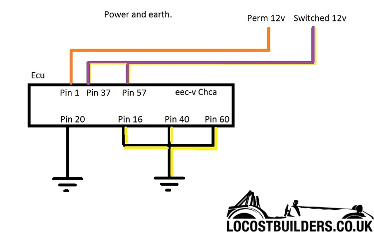
To check the pats you only need a few wires.
Two switched live 12v. One permanent live 12v and four earths. The aerial needs a switched live 12v and the Pats led needs a permanent 12v live.
PIN numbers are for a fiesta but the pictures may help.
Yes all the components are from the same car. This maye seam a daft question and i feel daft asking but what is the difference between a switched 12v
and normal 12v also what the difference between earth and switched earth
Thanks for helping me
Right i get that now thats what i thought but thought id double check..
Just dug the recept out and it says. Flashing alarm LED.. Is this my problem? it was from maplin and was the only led they sold with a resistor in it
and i seen alarm and thought it must be right
Right ive been out and disconnected the LED from the loom and put it on a battery ive got in the house and it just flashes so this must be the
problem. Is it only sending a signal to the ecu when the bulb is eliminated?