Zetecsierra
|
| posted on 13/10/16 at 06:52 PM |

|
|
Well big wasa. You absolute legend ive put the new led in today and boom it fired up lovely. I couldnt have done this without you so thank you so much
for all the help and advice all i have to do now is wire the fuel pump and starter relays properly as i do t understand from the diagrams witch wire
goes on which pin on the relays
|
|
|
|
|
big_wasa
|
| posted on 13/10/16 at 07:39 PM |
|
|
You don't really need the starter relay.
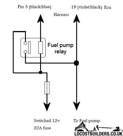
The fuel pump relay is easy. Ignor the PIN numbers.
So the ecu switches the earth side of the relay.
[Edited on 13/10/16 by big_wasa]
|
|
|
Hammy360
|
| posted on 13/10/16 at 08:24 PM |
|
|
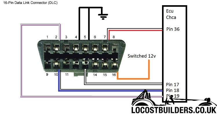
So 99% of my ecu is the same as Warrens description but on mine pin 80 has a white wire coming from it????
Also my RDB /Datalink connector is very different and Im a bit lost here....
Im at the part of my project now where its all about this wiring so I'll probably be posting a few more questions in this thread. Thankful for
the experiences and expertise guys....


[Edited on 14/10/16 by Hammy360]
Hammy
|
|
|
big_wasa
|
| posted on 14/10/16 at 06:09 PM |
|
|
I can't see all the pin colours and positions but it looks ok to me ?
This is the fiesta one I did..
|
|
|
Hammy360
|
| posted on 14/10/16 at 06:25 PM |
|
|
Thanks mate, I'll check against that
Hammy
|
|
|
Hammy360
|
| posted on 15/10/16 at 05:49 PM |
|
|
Got it now I think mate, cheers!
quote:
Originally posted by big_wasa
I can't see all the pin colours and positions but it looks ok to me ?
This is the fiesta one I did..
[Edited on 15/10/16 by Hammy360]
Hammy
|
|
|
Hammy360
|
| posted on 22/10/16 at 11:51 AM |
|
|
Is this a standard circuit image for a relay? (sorry no sparky me!) Im not sure how it relates to a relays pins as Im looking at them, can anyone help
please?
Cheers
quote:
Originally posted by big_wasa
You don't really need the starter relay.
The fuel pump relay is easy. Ignor the PIN numbers.
So the ecu switches the earth side of the relay.
[Edited on 13/10/16 by big_wasa]
Hammy
|
|
|
turnipfarmer
|
| posted on 22/10/16 at 01:14 PM |
|
|
Connect ECU pin 54 to relay pin 86
Connect a short wire to relay pin 85. Twist the bare end of that wire, together with the bare end of a wire coming from a +12v switched feed. Put a
connector on the twisted pair and plonk on relay pin 30
Twist the bare end of the wire from ECU pin 54 with the bare end of the wire feeding power to the fuel pump(s). Again put a connector on the twisted
pair and plonk on relay pin 87
|
|
|
Hammy360
|
| posted on 22/10/16 at 02:21 PM |
|
|
quote:
Originally posted by turnipfarmer
Connect ECU pin 54 to relay pin 86
Connect a short wire to relay pin 85. Twist the bare end of that wire, together with the bare end of a wire coming from a +12v switched feed. Put a
connector on the twisted pair and plonk on relay pin 30
Twist the bare end of the wire from ECU pin 54 with the bare end of the wire feeding power to the fuel pump(s). Again put a connector on the twisted
pair and plonk on relay pin 87
Cheers
Hammy
|
|
|
AlbertaSafari
|
| posted on 24/10/16 at 10:48 PM |
|
|
First off; a very special thanks to Big Wasa for this incredible post and Turnip Farmer for his Laymens diagram and countless hours on the phone
helping me out
And of course, this site.
For those of you in North America (Im in Canada) attached are the Pinouts for the (USA/Canadian) Focus Zetec using ECU: LFQ1. As noted previously;
they are all quite similar, but I thought I would include it for anyone on this side of the pond.
One critical thing to note is that the US and Canadian Ford Focus uses a returnless style fuel injection system. This means that a fuel pump control
module controls the voltage to the fuel pump to regulate and maintain the correct rail pressure ~40psi and there is no fuel pressure regulator on the
fuel rail
Effectively, Pin 54 on the ECU (Black & White) is not a switched earth, but a fuel pump output voltage from the fuel pump monitor to
measure to the duty cycle!!! No need to be confused, but in a nutshell this means that Pin 54 on the USA/Can ECUs is not a switched earth and it will
not get your fuel pump relay to work. You need to use a different switched earth or ground the fuel pump relay (Fuel Pump Relay Pin 86) directly to
the car as I did and install a fuel pressure regulator (I used one from a 1997-2000 Ford Contour or Mercury Mystique) to the end of the fuel rail with
the output line going back to the swirl pot.
This means that once you turn on your ignition switch the high and low pressure fuel pump will run until you shut your car off. Not an issue, unless
you get into an accident and there is fuel spraying out at 40psi! Talking to some others, it sounds like their fuel pump runs all the time anyway. I
would have thought that the switched earth on the European models would have switched the earth off once spark was no longer present, or something
like that. It sounds like Pin 54 on the European Zetec is nothing more than just a switched earth that grounds out once the ignition is turned on
anyway. I suppose Ford has an inertia fuel cut-off switch for this reason
If you are concerned about this, you can always wire in an inertia fuel
cut-off switch I suppose. I am not worried about it as I may just install a fuel cut-off switch on the dashboard.
As this is a locost site, I thought some of you may be interested in my manifold solution. I ended up using a Focus ST170 lower intake manifold and
then I made a plenum out of 3 PVC high efficiency furnace pipe Tees (3 x 3 x 1.5) with the 3.5 sections cut back so that the 1.5 ports lined up
with ST170 manifold ports. 2.25- 2 silicon couplers were then clamped to connect the plenum and ST170 intake. This pipe is rated for continual
furnace exhaust temperatures of 65C and 300psi, so I thought I would try it. There are more options with ABS sewer pipe, so next time I would likely
use that as my turbo engine will not be pushing anything greater than 12psi anyway and half of the parts on the engine are modified ABS plastic anyway
(Valve cover, thermostat housing, intake manifold, etc). I ported the IDs of the 1.5 PVC Tees to match the ST170 ports (They are actually slightly
oval) and I also radiused the IDs to hopefully improve flow. You then can use a 3 x 2 ABS or PVC adapters for the ends of the plenum while gluing
on 4mm or thicker aluminum plate (The thicker the better), with construction adhesive (Let it dry for 24hrs). First drilling out the MAF mounting
holes, taping any vacuum bungs, and boring out the MAF port with a hole saw. PL Quick set is terrific
(http://www.loctiteproducts.com/p/pl_ca_prem_adv/overview/Loctite-PL-Premium-FAST-GRAB-Polyurethane-Construction-Adhesive.htm). It all sounds
complicated, but you can see it all better in the pictures.
As noted by others, the ST170 lower intake manifold actually bolts right up the Zetec-R 2.0L engine, but the intake throats are smaller. To fix this,
just push out the steel sleeves for each bolt/stud cut-out from the ST170 manifold and cut the top part of the steel sleeve out making enough gap so
that the stud/bolt clears your new cut-out. Now push your new cut-out steel sleeves back into the manifold with the spacer void that you cut out
facing the 12-Oclock position. This will drop the manifold the ~2mm you need without drilling out the plastic manifold
Placing the modified steel
sleeves back in the manifold will ensure you dont over torque or crack the manifold once you torque all the intake bolts and nuts back to spec. You
will now notice that the bottom of the intake runners line up perfectly, but the top do not
You will have you carefully use a dremmel or die grinder
with a small cylindrical sanding attachment to modify the cylinder head intake size to eliminate the final restriction on the top part of the intake.
You will also need to increase the injection portion of the intake port to account for the size difference. So you dont remove too much material, you
will need to sand and then lightly bolt up the ST170 intake and note areas that need further material removal. It takes a little while, but if you
take your time it will all work out great.
Dont feel bad about doing this head modification, as the ST170 intake ports are larger than the Zetec-Rs, so this modification may net you a couple
HPs and is required to properly align the ports on the manifold. Make sure you plug up the holes of the intake carefully with rags before you start
so that the aluminum dust doesnt go into your engine and valves! Also make sure you use the ST170 intake gaskets too when you button everything back
up.
The car starts and idles nicely given the fact that I have 40lb injectors installed for my turbo setup. And the plenum only cost me about $100 CAD (50
quid) plus the cost of the ST170 lower manifold. I have not completed everything as I have to finish installing the turbo.
Pictures to follow once I figure out how to do that.
|
|
|
-Andy-
|
| posted on 18/12/16 at 06:22 PM |
|
|
Escort
Hi all,
Sorry first post mary and all that jazz. I am currently in the process of installing a 2.0 blacktop into a MK4 Escort.
Just wanted to say thank you to you all for the diagrams and installation notes. As my car is a MFI not EFI i have a little more work involved but the
principles that i have gathered from here are brilliant.
Thanks
Andy
|
|
|
big_wasa
|
| posted on 18/12/16 at 06:26 PM |
|
|
Always good to hear and thanks for the recognition.
[Edited on 18/12/16 by big_wasa]
|
|
|
Hammy360
|
| posted on 4/3/17 at 04:22 PM |
|
|
OEM ECU and loom
I know this isnt the for sale section but I have a Zetec ECU with loom, two keys and immobiliser from a 2000 2.0 litre Mondeo blacktop. £75
The car was mine and a runner so its all good!
Hammy
|
|
|
pekwah1
|
| posted on 20/6/17 at 08:56 AM |
|
|
Hi all,
I'm sure I'm maybe being blind, but I can see what wires I need from the ECU for the lambda sensor.
It's a 2000 blacktop.
Thanks in advance
|
|
|
big_wasa
|
| posted on 20/6/17 at 09:58 AM |
|
|
It has four wires and three come from the ecu. The fourth being a switched 12v for the sensor heater.
The heater is controlled by a switched earth on pin 93 black with yellow trace.
The sense wire is a White wire from pin 60 and to complete the circuit you tap in to pin 91 this is Brown and is a common to lots of sensors.
[Edited on 20/6/17 by big_wasa]
|
|
|
pekwah1
|
| posted on 20/6/17 at 11:14 AM |
|
|
Perfect, thanks wasa!
|
|
|
big_wasa
|
| posted on 20/6/17 at 02:32 PM |
|
|
No problem, that's mondeo not focus pin numbers.
|
|
|
pekwah1
|
| posted on 20/6/17 at 04:27 PM |
|
|
Good stuff, as it's a mondeo engine I've got!
|
|
|
spegru
|
| posted on 29/7/17 at 04:13 PM |
|
|
Key
One of my setups is going a bit 3 cylindery and I suspect the same problem I had before with one of the pins to the ECU getting tired. So I was
looking out for a replacement
I've noticed plenty of zetec ECUs on Ebay but loads of them are without keys - which I would have thought would make them useless?
Does anyone have a cheap and cheerful method of recoding?
|
|
|
turnipfarmer
|
| posted on 29/7/17 at 04:54 PM |
|
|
Here's one
ENGINE ECU KEY TRANSPONDER SET 98-01 Ford Cougar 2.0 Petrol & WARRANTY - 1190575
|
|
|
big_wasa
|
| posted on 29/7/17 at 05:50 PM |
|
|
quote:
Originally posted by spegru
One of my setups is going a bit 3 cylindery and I suspect the same problem I had before with one of the pins to the ECU getting tired. So I was
looking out for a replacement
I've noticed plenty of zetec ECUs on Ebay but loads of them are without keys - which I would have thought would make them useless?
Does anyone have a cheap and cheerful method of recoding?
Previously I would have said it can't be done, but now " in theory " it can.
https://passionford.com/forum/ford-focus-st/492781-gem-module.html
I've got the gear but not the extended licence as I havnt had time to play with it other than basic testing on the st220 engine.
|
|
|
spegru
|
| posted on 30/7/17 at 07:01 AM |
|
|
Thanks. My problem is with a 60 pin eec v so owl5 is no use.
On the elm gadget & software I've seen references to enabling disabling features but not coding keys. Do you have info that they do that
too?
|
|
|
big_wasa
|
| posted on 30/7/17 at 07:16 AM |
|
|
Yes mate but this isn't a standard elm or any generic software. You need that specific dongle and software and you need to apply for a short
term licence and show you have a genuine need.
I've hooked mine up to my st220 and it reads all the moduals on the car and goes far deeper than say an elm dongle with torque. I can't
test the functions needing the licence as I havnt got it.
Functions, it's not as function rich as you may think. You don't seem to be able to disable seat belt functions for a track day car ect.
|
|
|
big_wasa
|
| posted on 30/7/17 at 07:35 AM |
|
|
http://forscan.org/forum/viewtopic.php?f=6&t=839
|
|
|
spegru
|
| posted on 31/7/17 at 08:12 AM |
|
|
Wow that looks pretty comprehensive. I shall have to try it
|
|
|


