snippy
|
| posted on 27/8/13 at 06:21 PM |

|
|
wiring a single flasher relay for Indicators & Hazards
I am using a 3 pin Flasher Relay (pins 31, 49, 49a). Its marked as 4x21w + (2x5w) so should be ok to be used for Indicators & Hazards. I`ve got
the indicators working fine. I want to wire in a new hazard switch because the car I am rebuilding has never had hazards. I`ve got a simple 3pin
illuminated rocker switch to act as my hazard switch. Do I simply run a 12v+ switched feed wire from my rocker switch to pin 49 for the hazard
circuit? I`m using an old Escort mk1 loom by the way.
|
|
|
|
|
theduck
|
| posted on 27/8/13 at 08:18 PM |
|
|
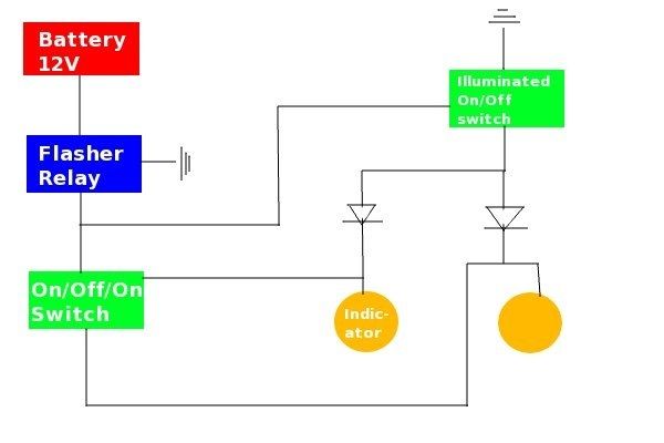
This superb diagram any help?
|
|
|
loggyboy
|
| posted on 28/8/13 at 08:43 AM |
|
|
Above is simplest solution if using standard switches. However it can cause a clash with hazards and indicators activated at the same time, not a
regulation issue, but would annoy me!
A relay linked to the hazard switch to deactivate the supply to the indocators would do the trick.
The other option is to use an OE hazard switch, which its own mechanism will deactivate the indcator supply when the hazards are on.
Mistral Motorsport
|
|
|
snippy
|
| posted on 4/9/13 at 04:51 PM |
|
|
Still struggling with this, not sure if I have understood above diagram correctly. Maybe I need an idiots guide? Anyone?
|
|
|
YQUSTA
|
| posted on 4/9/13 at 07:13 PM |
|
|
What part don't you understand?
"If in doubt flat out"
Colin McRae
|
|
|
blakep82
|
| posted on 4/9/13 at 07:38 PM |
|
|
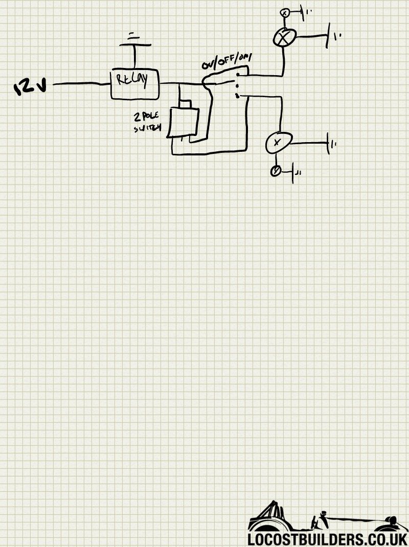
I dont like using diodes for this sort of thing.
What about this? Sorry about the blank page on this, but you should be able to see it ok. Small lights are the warning lamps
Of course I forgot the hazard warning lamp... hmmm cant remember how that bit worked now. I suppose you could put it on one output from the 2 pole
switch, would still need a diode though
[Edited on 4/9/13 by blakep82]
________________________
IVA manual link http://www.businesslink.gov.uk/bdotg/action/detail?type=RESOURCES&itemId=1081997083
don't write OT on a new thread title, you're creating the topic, everything you write is very much ON topic!
|
|
|
snippy
|
| posted on 4/9/13 at 08:12 PM |
|
|
Maybe it's easier if I just wire in a seperate relay for the hazards?
|
|
|
YQUSTA
|
| posted on 4/9/13 at 08:24 PM |
|
|
If you post a diagram of what you have at the moment it can be sorted very easy.
"If in doubt flat out"
Colin McRae
|
|
|
loggyboy
|
| posted on 4/9/13 at 10:07 PM |
|
|
quote:
Originally posted by blakep82
I dont like using diodes for this sort of thing.
What about this? Sorry about the blank page on this, but you should be able to see it ok. Small lights are the warning lamps
Of course I forgot the hazard warning lamp... hmmm cant remember how that bit worked now. I suppose you could put it on one output from the 2 pole
switch, would still need a diode though
What happens when you turn both hazards and an indocator on tho?
Mistral Motorsport
|
|
|
ReMan
|
| posted on 6/9/13 at 09:23 PM |
|
|
It still works. As noted this would still need diodes (or a different switch) to drive a dash warning light
www.plusnine.co.uk
|
|
|
snowy2
|
| posted on 8/9/13 at 08:40 AM |
|
|
does this work for you?
term 15 = ignition live
term 30 = battery live
The flasher receives power from one of 2 fuses, depending on whether or not the Hazard switch is operated. The same flasher is used for both Turn
Indicator and Hazard functions.
Internal circuitry in the flasher keeps a small "sense" voltage on Terminal #49a all the time. When the Indicator stalk is pulled to Left
or Right, the Indicator bulbs on that side are connected to Terminal #49a and load the flasher circuit so that it knows to begin flashing.
Immediately, the internal relay contact closes from (+) to #49a and the bulbs light. The flasher electronic circuit then turns the relay off and on to
provide the flashing cycle.
The 4-terminal flasher has a built-in load sensing relay which drives the dash indicator. The dash indicator flashes in time with the Turn Indicator
bulbs.
The dash speedo indicator bulb used with the 3-terminal flasher relay is connected from the (+) supply to #49a and it flashes opposite to the Turn
Indicator bulbs. For example, when the Turn Indicator bulbs are lit, there is +12V present at #49a. That means that both sides of the dash bulb have
+12V on them and no current can flow thru the bulb.
The only difference in circuit operation for Hazards is that the flasher receives power from the second fuse, which is live whether or not the
Ignition is switched On or not. The Hazard switch has another set of contacts (not shown here) which connects both Left and Right sets of bulbs to the
flasher.
this may also help...
and a link to the source site...
http://www.nls.net/mp/volks/htm/signals.htm
[Edited on 8/9/13 by snowy2]
sometimes you are the pigeon, most of the time the statue.
|
|
|