marco
|
| posted on 20/6/14 at 12:27 PM |

|
|
Savage switch dimming when sidelights on questions
I've done a quick bench test with a resistor and managed to get one switch working as follows
-Full lit when depressed as per normal (for daylight use 12 v feed to led+ from pin 1)
-Sidelights on the Led is dim (using 4k resistor inline with the 12v feed from sidelights pin2 to Led+)
-Sidelights on and full lit when depressed (pin 2 active when button depressed giving full12v to led+)
What I'm now not sure of is wiring all the remaining switches to link together and also whether I need any diodes which I have seen mentioned on
other posts about this?
Can I have one side light feed wire and take spurs off this with a resistor for each switch (to dim them)
Or can I use one resistor in line then take the spurs (or jump) to each switch.
Lastly are any diodes required at all and for what reason.
Oh and what size resistor 0.6w or 2w?
[Edited on 20/6/14 by marco]
|
|
|
|
|
z2000
|
| posted on 20/6/14 at 07:33 PM |
|
|
Marco,
I'm in a similar situation - I have bought a bunch of diodes to solder inline to each switch, all linked to the sidelight feed.
This means when one switch is lit (when you switch it on), the electricity can't flow in 'reverse' and reach any of the other switch
LEDs.
I am unsure if I need a resistor for each switch or one will be sufficient for all; I have bought a variable resistor to test (I am only using around
4/5 switches) and I will see if I can use it to vary the brightness such that I have the ability to adjust whenever I like.
You could use trial and error to find an optimal resistance or use some simple maths based on the number of LEDs and how much voltage an LED (in your
chosen switch) needs to give the desired brightness.
If you like I can produce a simple wiring diagram...?
If it isn't broken; take it apart and fix it! Build PhotoBlog:
http://z2000.co.uk
|
|
|
barbarianbeast
|
| posted on 20/6/14 at 07:50 PM |
|
|
Will the same amount of switches always be lit? Because otherwise your switches will vary in brightness depending on how many are on if you use just
a single resistor. Best to use a resistor on each to avoid that. I would of thought 0.6 watt to be OK too, easiest way to check is to measure the
voltage drop directly across the resistor, square it then divide it by your resistance in ohms e.g (V^2/R) = W
|
|
|
z2000
|
| posted on 20/6/14 at 08:43 PM |
|
|
I thought the same; if using the sidelights feed, in theory your number of switches which it will light up will remain constant, unless you decide to
remove switches from the circuit.
The only other change will be when you power the switch led at full brightness, this may cause the other leds to become slightly brighter due to the
share of the sidelight feed going to one less led..but if you have a few lights this change will be less noticeable.
But as suggested, individual resistors may be the safest bet.
If it isn't broken; take it apart and fix it! Build PhotoBlog:
http://z2000.co.uk
|
|
|
jrrsparky
|
| posted on 20/6/14 at 08:43 PM |
|
|
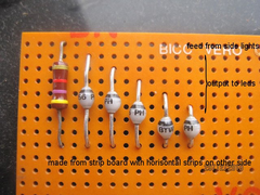 
dashlights
One resistor will do as when you switch on the side lights all the linked LEDs will will come on dim,
|
|
|
marco
|
| posted on 20/6/14 at 09:52 PM |
|
|
Sounds like I'm nearly there then thanks Z2000
If we used one resistor jrrsparky then am I correct in thinking a diode is still required on each line to prevent this feed back?
|
|
|
jrrsparky
|
| posted on 20/6/14 at 09:57 PM |
|
|
Yes you will still need the diodes either way.
|
|
|
marco
|
| posted on 22/6/14 at 08:57 AM |
|
|
Ok great
Next question how do you make the dimming leds work with the flasher/hazard switch. I need both sides of the switch for the hazards I believe which
removes the option of the dimming led idea with sidelights on?
|
|
|
marco
|
| posted on 22/6/14 at 09:20 AM |
|
|
Is this my solution, rather than the diagram below can I use one side of the savage switch as
Pin1 Flasher feed from toggle switch centre pin (from flasher relay)
Pin 2 to both left and right indicator wires with diodes in line
I am not bothered about the savage led flashing when depressed as I have hazard warning in my digital dash board. Also the 3 pin side of the switch
will give me a brighter led when depressed at night or day showing the switch is depressed.
 
|
|
|