I am just working on mocking up the exhaust headers for my Rover v8. Following a couple of weeks of googling, I am working with 40mm OD plumbing pipe
since most of the pages I found said that is the diameter that the metal headers should be. I've made the merge collector with a 50mm exit hole
but that's not a fixed dimension right now (just how it happened to turn out)
Basically, I'm hoping the collective genius of the forums can give me some input on whether this header design looks ok? I'm not looking
for equal-length headers or something that'll give me uber performance, but equally I'm not looking for something that's going to
make the engine run really badly.
I posted this question on another forum as well - I'm just trying to get as many smart people as possible to give feedback
Mark: Nice idea - closer to equal length without any extra hassle
loggyboy: I was trying to get the pipes to exit the body as close as possbile, to minimise the hole in the bodywork - I could only find those 90
degree bends in plastic, but hope to replace any 90's with 2.5D stainless bends
Im sure you can get nice curves as the design goes on.
Working from left to right as 1-4;
Keep 1 where it is.
2- to the left of 1.
3- above 2.
and 1 to the right of 2.
That will equal your lengths more.
I think you are going to end up doing the exercise twice, as the bends you find will not have the sharp radius of the plastic elbows. Get the steel
parts and start with them. This based on my experience making these for my Rover V8.
Although mine is a rear engined application you could use the same approach
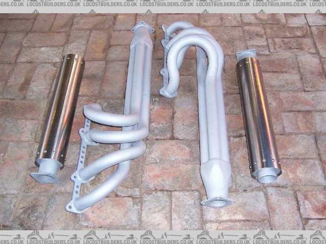
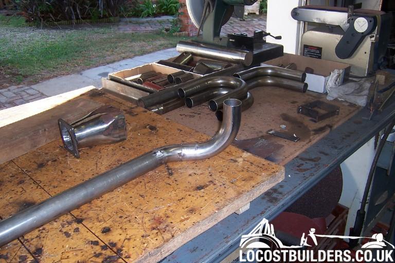
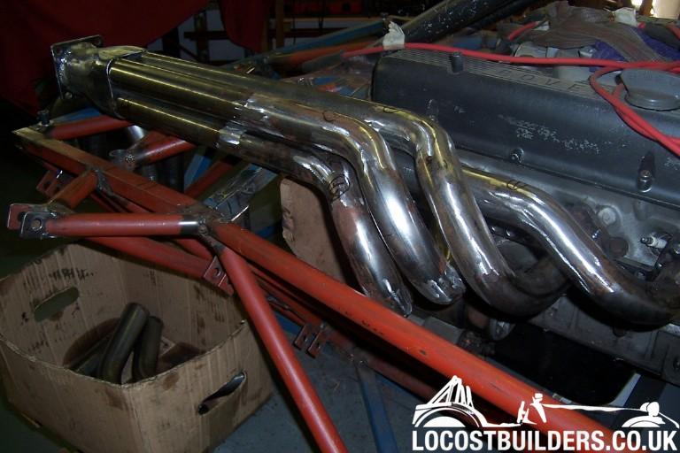
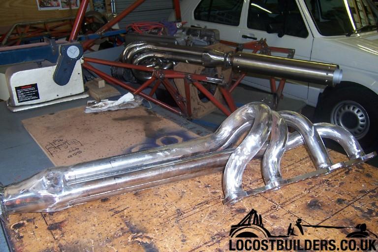
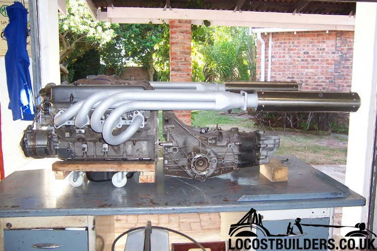
I used 26 off 90 deg carbon steel mandrel bends and laser cut 10 mm thick head flanges. Pipe welds are metal finished flush. Each header pipe is 850
mm long, (tolerance +/- 10 mm). Collectors taper to 2.5", fabricated from 3" pipe. Silencer cans are 500 mm long, made from 4"
stainless thin wall tube, with 2.5" perforated tube inners. Carbon steel parts sandblasted and painted with matt silver high heat paint. Once
they are proven I plan to ceramic coat them.
What I did:
Bought 90 deg mandrel bends in 38 x 1.6 mm mild steel.
Had head flanges laser cut, so that pipes are fitted with a butt joint to flange.
Bolted flanges to head with wood plugs fitted sticking out of flanges to give me a positive, but movable location for the first bend.
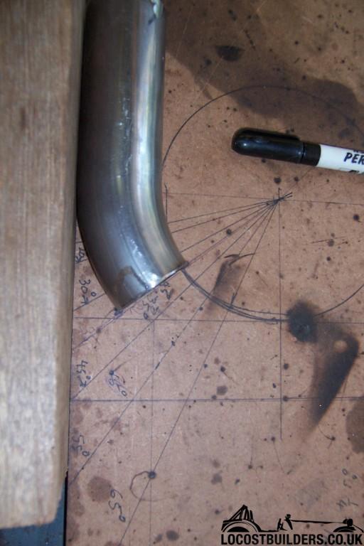
Drew circles on plank of wood the same diameters as inside and outside radius of mandrill bends.
Marked off angles 15, 30, 45 etc, on circles to use as a template to ensure I always cut the bends true to the pipe bore.
Made up first pipe for #1 cylinder as this had longest straight section by tacking elbows, cut elbows and straight pipes together. Try to cut to exact
angles where possible.
Cut #1 pipe to desired length, using calculated length along mean pipe radius to determine total length (straight length+x deg+x deg etc).
Now that position of collector is established, by trail and error join #2 pipe to collector, by joining bends in more than one orientation where
necessary.
Don't cheat by cutting joining planes not perpendicular to pipe bore.
I found it easiest to work from rear to head, and keeping the flange to pipe joint loose till the last join.
Repeat for #3 and #4 pipe.
Depending how keen you are on keeping the pipe spacing more or less consistent and parallel, this can drive you crazy.
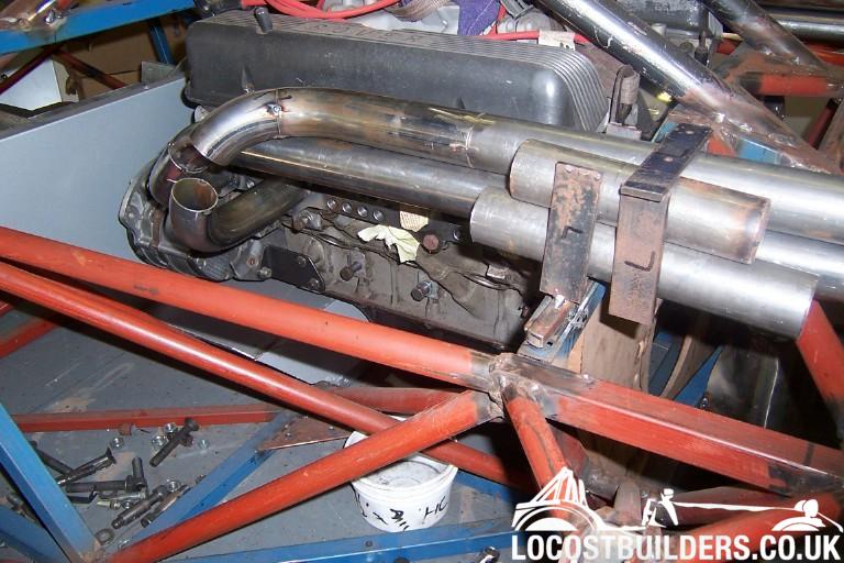
I found it helped a lot to make some square frames from flat bar to fit around the 4 pipes where they ran parallel, to keep them in position while
tacking bends
Once all pipes are tacked up, remove from flanges again.
Weld up all pipes fully, using TIG if possible, or MIG.
Metal finish if required or desired
Reassemble manifold, and do final head flange to pipes and collector welds. Remember to fit closing plate between pipes at collector.
Duplicate the detail for the other side.
[Edited on 12/8/14 by Fred W B]
[Edited on 12/8/14 by Fred W B]
You can do it quickly. You can do it cheap. You can do it right. Pick any two.
I started with the plastic because I had literally no clue what the design was going to be - I've already decided to start again and take
maccmike's suggestion to move the front two cylinders to the inside, and the rear two to the outside, in order to get the pipes closer to equal
length with very little faffing around.
I was basing my activity on a set of videos on YouTube about header design. If you look at this one:
around the 2:45-2:55 mark you'll see that they used a tight 90 in the mockup, but a smoother curve in metal (2.5D? Just guessing..) -
that's what I was planning to do.
The plan in the video involves buying a bunch of exhaust clamps, then tacking them to some scrap box to hold them in place, removing the plastic
version and getting the steel version to fit exactly into the clamps.
Does this look feasible? The guys in the video are obviously professionals, and by now it should be obvious I'm not
Certainly that does work, as the video demonstrates, and it would be the only way you could make a header if the car should not be in front of you
whan you fabricate the steel parts.
Also your possibly wasted material in trial and error is (cheap?) plastic, rather than steel, but in the context of the time and effort to make
manifolds like these the material cost is insignificant.
Considering the amount of work of fitting up the plastic, and making the jig, I don't regret starting directly with the actual parts. Also it
doesn't help you with the challenge of getting the second side to match the first. If I did it again I would work on both sides at the same
time, rather them finishing the first side and then trying to make the second side to match the first.
[Edited on 12/8/14 by Fred W B]
You can do it quickly. You can do it cheap. You can do it right. Pick any two.
Thanks for all the replies - I've been out of the country for work for a while but I got back this weekend and managed to get some work done,
due to the bad weather I didn't have to work on the garden
I managed to eliminate the 90 degree bends, and got the lengths closer to equal. I'm thinking about swapping the middle two pipes around, in
order to make the lengths more even..
I looked at that same video before doing mine, I also mocked up in cad but in the end I just bought some pipe and broke out the angry grinder and
welder!
Its not that pretty, but once its painted and heat wrapped no bugger will see!
No, its mild steel, the kit came second hand from a chap who'd decided against making his own. I believe its an ebay job - I think
pepperperformance? Quality of joins is basic, but I think they are priced to suit their quality!
Design #3 - I managed to eliminate an elbow with this one, I think this might be the one I'll go for in steel.
The research I've done seems to indicate that same-length headers is only really required on high bhp engines, and only makes a few bhp
difference, so I'm not too worried about the difference between the longest and shortest here (about 15cm).
Nice! How much were they, all in, if you don't mind me asking?
I know it was about 4 years ago, but should give me a rough idea. I've pretty much decided that I'm going to get someone else to make them
up, once I investigated how much a tig welder (ac/dc so I could do ally later) would cost, and added that to the cost of a tig course and a bunch of
stainless mandrel bends
Equal length is also not really relevant on the RV8 as you do not have even firing pulses for each bank.
the pulses in that collector are not 180 degree evenly spaced as they would be in a an I4, for tuned lengths on a crossplane you need to match equal
length from one bank to the other not just on one bank. Better to make it easy for yourself rather than getting equal length for no real benefit.
quote:Originally posted by rincewind23
Design #3 - I managed to eliminate an elbow with this one, I think this might be the one I'll go for in steel.
The research I've done seems to indicate that same-length headers is only really required on high bhp engines, and only makes a few bhp
difference, so I'm not too worried about the difference between the longest and shortest here (about 15cm).