andylancaster3000
|
| posted on 1/12/14 at 02:25 PM |

|
|
CAD Help - Iges import issue
Hi all,
One for the CAD experts (....or the better amateurs than me!)
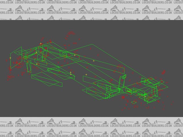
I have an IGES file generated from a Faro arm measurement of our car's spaceframe and need to try turning this in a 3D model. The iges is made
up of a load of planes and 'circles' which if viewed in an open-source iges viewer I can see (as below). However when I open the file in
something like solidworks or solid edge I can only see the planes.
Anyone got any clues as to what I doing wrong?!
|
|
|
|
|
bart
|
| posted on 1/12/14 at 02:36 PM |
|
|
could be on different layers
switch all layers on.
|
|
|
HowardB
|
| posted on 1/12/14 at 05:01 PM |
|
|
interesting problem that throws up loads of answers in the forums. Which SW are you using.?
have a read of this,,...
linky
Howard
Fisher Fury was 2000 Zetec - now a 1600 (it Lives again  and goes zoom) and goes zoom)
|
|
|
43655
|
| posted on 1/12/14 at 07:18 PM |
|
|
I could open it in solidworks for you if you like, check the model?
lines and circles sounds like solidworks weldments that haven't become features
|
|
|
Alan B
|
| posted on 1/12/14 at 07:37 PM |
|
|
I've worked a bit on this kind of stuff, and unless I'm mistaken I'm not really sure how you can do this.
With your point data how does it know which 2 points form a line? which 3 points form a plane?
I guess there is some intelligence in the software, but without hundreds of points I don't see how it can be done?
Love for someone to enlighten me otherwise.
|
|
|
twybrow
|
| posted on 1/12/14 at 09:15 PM |
|
|
quote:
Originally posted by Alan B
I've worked a bit on this kind of stuff, and unless I'm mistaken I'm not really sure how you can do this.
With your point data how does it know which 2 points form a line? which 3 points form a plane?
I guess there is some intelligence in the software, but without hundreds of points I don't see how it can be done?
Love for someone to enlighten me otherwise.
When scanned, presumably the user can tell the software that 'these next four points define a plate surface'? With the metrology kit I
have used, the data is generally just a point cloud, which then has to be post-processed. Also, we typically load into the metrology kit the CAD model
we are trying to compare against (which is something that cant be done if reverse engineering as the OP is trying to do)....
|
|
|
Alan B
|
| posted on 1/12/14 at 09:19 PM |
|
|
quote:
Originally posted by twybrow
quote:
Originally posted by Alan B
I've worked a bit on this kind of stuff, and unless I'm mistaken I'm not really sure how you can do this.
With your point data how does it know which 2 points form a line? which 3 points form a plane?
I guess there is some intelligence in the software, but without hundreds of points I don't see how it can be done?
Love for someone to enlighten me otherwise.
When scanned, presumably the user can tell the software that 'these next four points define a plate surface'? With the metrology kit I
have used, the data is generally just a point cloud, which then has to be post-processed. Also, we typically load into the metrology kit the CAD model
we are trying to compare against (which is something that cant be done if reverse engineering as the OP is trying to do)....
Yes, the comparing to existing CAD model scenario is what I'm familiar with.
|
|
|