lsdweb
|
| posted on 25/10/16 at 09:31 AM |

|
|
Crank Sensor wiring through multi pin plug
Hi All
I'm making up a new engine wiring loom for my Clio as I'm fitting an Emerald ECU (and ditching all the crappy French electrics which
probably lost me the Welsh Championship this season!).
The loom will have a multi pin plug (ITT Cannon) at the bulkhead so that the engine can be removed with everything connected up.
My question relates to shielding - the crank pickup will be wired using shielded cable but how do I keep the integrity of the shielding through the
multi pin plug? My gut feel is that this will be difficult to achieve so I may wire the crank sensor separately.
Any thoughts?
Ta
Wyn
|
|
|
|
|
britishtrident
|
| posted on 25/10/16 at 10:27 AM |
|
|
The shielding is just an extra ground connection --- only connect to the ECU ground at one end to avoid problems if the main engine ground fails
and tries to earth the starter current through the ecu.
If you want to use a separate bulkhead style connector you might want to consider an "avaition style" connector these are available
very cheaply on ebay with many different numbers of conductors and they can't be confused with other connectors.
[I] What use our work, Bennet, if we cannot care for those we love? .
― From BBC TV/Amazon's Ripper Street.
[/I]
|
|
|
r1_pete
|
| posted on 25/10/16 at 11:20 AM |
|
|
The shielding is there to protect the sensor signal to the ECU from electrical 'noise' generated by the alternator, the HT circuits and
the like, thus preventing rogue signals reaching the ecu.
It really depends how far from the bulkhead those components are, if they are at the front of the engine, far from the bulkhead, then just use one of
the connector pins to join the engine bay shielding to the in car shielding. otherwise, as you say use a separate twin core and shield plug and
socket.
|
|
|
David Jenkins
|
| posted on 25/10/16 at 01:05 PM |
|
|
I used proper automotive-grade screened twin-core for my crank sensor. Like this
stuff.
|
|
|
lsdweb
|
| posted on 25/10/16 at 01:26 PM |
|
|
Thanks guys
Britishtrident - I knew about shielding one end only but didn't know why until now - thanks!
r1_pete - it's the unshielded but (probably about 2 inches) at the plug that worries me - that plug will carry the injector and coil wiring,
plus other sensors.
Regards
Wyn
|
|
|
David Jenkins
|
| posted on 25/10/16 at 01:35 PM |
|
|
You could try twisting the 2 wires together, where they are outside the braiding. This will reduce interference quite a bit (not that I think
you'll experience much anyway).
|
|
|
r1_pete
|
| posted on 25/10/16 at 02:20 PM |
|
|
I don't think you'll have any problems with a couple of un-shielded inches, inside the ECU plug and the sensor plug is also
un-shielded.
Its really the high voltages in the secondary coil windings (to the plugs) and the alternator windings which radiate interference, its extremely
unlikely the 12v feeds will cause you any problems.
The other reason for not connecting the shield at both ends is to prevent eddy currents being generated and causing more interference.
|
|
|
coyoteboy
|
| posted on 25/10/16 at 07:36 PM |
|
|
Any open section will allow noise in. It may be minimal but why risk it when there are dozens of multi core connectors with fully shielded back shells
etc?
|
|
|
silex
|
| posted on 25/10/16 at 09:37 PM |
|
|
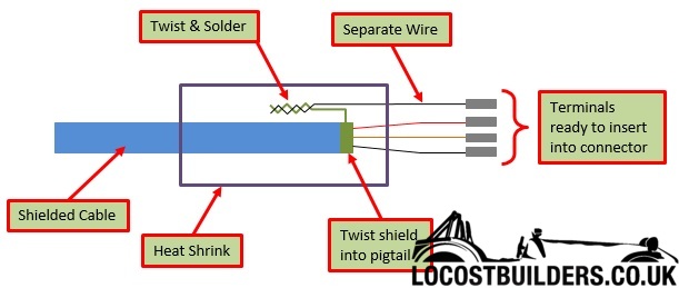
To pass a shield through the bulkhead connector the following method it used extensively;
1. Cut back the outside insulation approx 30mm to expose the shield
2. Unpick one side of the braid so you take the braid from an 'O' shape to a 'C' shape.
3. Pull the braid over to the side opposite the section you unpicked leaving the internal wires behind. Now twist the braid together to form a pigtail
wire out of the braid. Fold the shield pigtail back so that it points down the cable length.
4. Take a spare piece of wire, preferably black (to signify a ground) and of a similar size to the signal/core wires. Twist one end of this wire
together with the shield pigtail and apply a little solder to maintain a good connection.
5. Cover the joint with heat shrink tube - preferably adhesive lined type.
6. Trim the black wire to the same length as you core wires.
7. Attach the terminals and insert into the connector.
The idea is to keep the unshielded portion as short as possible. You have to do the same at both sides of the bulkhead. You can use the same method to
connect into the ECU connector.
The downside is that you need to use a pin in the bulkhead connector.
[Edited on 25/10/16 by silex]
Murphy's 2 laws
1. If it can go wrong it will
2. In case of emergency - refer to rule 1.
|
|
|
hearbear
|
| posted on 25/10/16 at 10:43 PM |
|
|
quote:
Originally posted by silex
To pass a shield through the bulkhead connector the following method it used extensively;
1. Cut back the outside insulation approx 30mm to expose the shield
2. Unpick one side of the braid so you take the braid from an 'O' shape to a 'C' shape.
3. Pull the braid over to the side opposite the section you unpicked leaving the internal wires behind. Now twist the braid together to form a pigtail
wire out of the braid. Fold the shield pigtail back so that it points down the cable length.
4. Take a spare piece of wire, preferably black (to signify a ground) and of a similar size to the signal/core wires. Twist one end of this wire
together with the shield pigtail and apply a little solder to maintain a good connection.
5. Cover the joint with heat shrink tube - preferably adhesive lined type.
6. Trim the black wire to the same length as you core wires.
7. Attach the terminals and insert into the connector.
The idea is to keep the unshielded portion as short as possible. You have to do the same at both sides of the bulkhead. You can use the same method to
connect into the ECU connector.
The downside is that you need to use a pin in the bulkhead connector.
[Edited on 25/10/16 by silex]
This is the way we did it when fitting multipin bulkhead connectors and never had any problems. Should also have said keep the twisted pair twisted
right into the connections in the plug.
[Edited on 26/10/16 by hearbear]
3.9Ltr SSC Stylus should be fun
|
|
|
coyoteboy
|
| posted on 25/10/16 at 11:20 PM |
|
|
Ship something decent in to do the job properly....
P55K-30 30 Pin Straight Non-screen General Electric Circular Connector
Though not that one, as it's not a screened variant.
Though there's nothing better than running it through it's own screened connector - so you don't get noise from the other pins.
[Edited on 25/10/16 by coyoteboy]
|
|
|
froggy
|
| posted on 26/10/16 at 07:12 PM |
|
|
I helped a mate do his vr6 turbo with ms and we had issues with the crank trigger signal until we moved the cable away from the rest of the loom .
I've done my car with the the shielded cable on the other side of the engine on its own and haven't had any sync or trigger problems with
no split just the connector on one end for the sensor and a cable right up to the ecu plug
[IMG]http://i144.photobucket.com/albums/r187/froggy_0[IMG]
|
|
|
lsdweb
|
| posted on 27/10/16 at 09:15 AM |
|
|
Thanks all!
Lots to think about. I haven't had my ECU back from Emerald yet so will wait for this to wok out where to fit the ECU before progressing with
any wiring.
Ta
Wyn
|
|
|