Rorty
|
| posted on 16/1/03 at 12:34 AM |

|
|
In that particular instance, I would leave well alone. Those shock bushes are a prime example of where a rubber/Metalastic bush actually performs
within its limits.
The deflection of the shock during wheel travel is a lot less than the wishbone pivots typically see. Therefore, the bush merely flexes, and the
rubber is man enough for the job, as rotation of the shock eye around its mounting bolt is minimal.
The reason rubber shock bushes wear out quickly is more to do with their diminutive size, and the pounding they take, rather than anything to do with
being torn apart by rotational force.

Cheers, Rorty.
"Faster than a speeding Pullet".
PLEASE DON'T U2U ME IF YOU WANT A QUICK RESPONSE. TRY EMAILING ME INSTEAD!
|
|
|
|
|
kb58
|
| posted on 21/1/03 at 04:10 AM |
|
|
Back to the original topic. The way I did it was by building it in reverse. That is, I built up a fixture which held the suspension arm rod-ends at
the exact points in space relative to each other. The fixture was then "offered up" to the chassis and fixed in position. The beauty of that is
you then simply build brackets out from the chassis with bolts already passing through the rod-ends. That way you know for SURE that it's exactly
where it should be.
|
|
|
stephen_gusterson
|
| posted on 21/1/03 at 08:13 PM |
|
|
whatever happened to lasermans great idea of a pre manufacured weld on box type front end with brackets attatched?
atb
steve
|
|
|
Mark Allanson
|
| posted on 21/1/03 at 09:20 PM |
|
|
The weld on box would be only as good as its fitment. Have a peep at "castor angle" in Running Gear so see the accuracy required to maintain the
castor angle.
|
|
|
dougal
|
| posted on 9/2/03 at 11:45 PM |
|
|
im not getting involved in the argument but from my point of view as an engineer is that if you are going to let the tube rotate around the bush the
make sure that the bolt outer to tube inner clearance is very small or else any slop will allow the sleve to machine the bolt causing stress raisers
allowing cracks in the bolt.
im not sure what im gonna use.
|
|
|
jcduroc
|
| posted on 26/2/03 at 11:45 PM |
|
|
Susp mounting
quote:
Originally posted by Rorty.
... Another instance of a crush tube, is the short length of tube you would weld through a chassis member through which you would insert a bolt for
the likes of a seat belt shackle. In this case, the crush tube prevents the seat belt bolt from crushing the surrounding chassis member.
...
Rorty
How would a front wishbone mounting be, IYO (in your opinion), crossing the chassis member tube?
João
|
|
|
Rorty
|
| posted on 27/2/03 at 03:34 AM |
|
|
IIUYC (if I understand you correctly)  There's no reason why that can't be done in
theory. I've seen both Rose joints and studded brackets mounted through chassis members before. Obviously, the hole in the chassis member would need
to have a crush tube welded in. There's no reason why that can't be done in
theory. I've seen both Rose joints and studded brackets mounted through chassis members before. Obviously, the hole in the chassis member would need
to have a crush tube welded in.
The problem with mounting a Rose joint in such a manner, is the short amount of thread. It is surmountable by using a 2X adjuster in the chassis,
which means the Rose joint is infinitely adjustable, and never needs to be removed for adjustment. The weight penalty and extra components/machining
may render it unsuitable for all but the racing 7esque Locosts though.
The glory of mounting everything through the chassis is, initally, you just have to drill some 19mm holes, and weld in the crush tubes. After that,
all the brackets can be bolted in. A neat trick would be to position the studs on the back of the brackets off centre, so by rotating them 180
degrees, you would have a different amount of caster.
If any other dimensions needed to be varied at a later date, new brackets with suitably off-set studs could be inserted.
Is that what you meant, or have I totally missed the mark? 
Cheers, Rorty.
"Faster than a speeding Pullet".
PLEASE DON'T U2U ME IF YOU WANT A QUICK RESPONSE. TRY EMAILING ME INSTEAD!
|
|
|
Fast Westie
|
| posted on 27/2/03 at 10:51 AM |
|
|
quote:
I've seen both Rose joints and studded brackets mounted through chassis members before
Caterham do this quite regularly, even in the wishbones.
The car in front is a Westfield
|
|
|
jcduroc
|
| posted on 27/2/03 at 10:57 PM |
|
|
[quote There's no reason why that can't be done in theory. I've seen both Rose joints and studded brackets mounted through chassis members before.
Obviously, the hole in the chassis member would need to have a crush tube welded in... The glory of mounting everything through the chassis is,
initally, you just have to drill some 19mm holes, and weld in the crush tubes... Is that what you meant, or have I totally missed the mark?
What I mean is something like this (apart from the very poor drawings, just done them on the spot/over my knees)
[img]C:\Documents and settings\administrator\my documents\my pictures\FrSuspWishboneWithUNIBALLOnChassisTube.gif[/img]
or this, with bushes
[img]C:\Documents and settings\administrator\my documents\my pictures\FrSuspWishboneWithPolybushOnChassisTube.gif[/img]
what do you think?
João
|
|
|
jcduroc
|
| posted on 27/2/03 at 11:05 PM |
|
|
[img]C:\Documents and settings\administrator\my documents\my pictures\FrSuspWishboneWithUNIBALLOnChassisTube.gif[/img]
or this, with bushes
[img]C:\Documents and settings\administrator\my documents\my pictures\FrSuspWishboneWithPolybushOnChassisTube.gif[/img]
what do you think?
Ignorant I am, pictures do not show up, so I uploaded them to my Photos area (jcduroc)
João
|
|
|
Rorty
|
| posted on 28/2/03 at 12:26 AM |
|
|
OK, I totally misunderstood you. What you're illustrating, is actually a wishbone pivot, mounted in "single shear" i.e. it has a shear path in just
one place, as opposed to the more common double shear bracket, that supports both sides of the pivot.
I certainly wouldn't recommend a single shear mount for the lower wishbone, as it is quite highly loaded, however, it would be suitable, though not
ideal, for the upper wishbone mounts.
You would have to ensure the crush tube has a wall thickness of at least 3mm, and is correctly positioned. Needless to say, you would want to use a
grade 8 imperial bolt, or a 10.9 metric bolt, and observe the correct torque figures when tightening.
A fail-safe washer would also have to be used. A FS washer is to prevent the wishbone eye coming off the bolt in the event the bush fails. The same
goes for any type of pivot mounted in single shear. The washer would need to be about 10% larger in diameter than the wishbone eye, and not less than
3mm thick. See attached pic. 
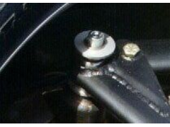 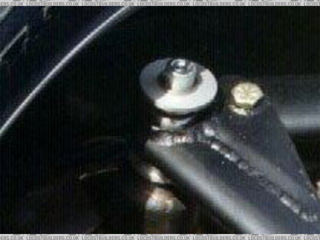
Rescued attachment fail_safe_washer.jpg
Cheers, Rorty.
"Faster than a speeding Pullet".
PLEASE DON'T U2U ME IF YOU WANT A QUICK RESPONSE. TRY EMAILING ME INSTEAD!
|
|
|
fastenuff
|
| posted on 28/2/03 at 06:53 PM |
|
|
hi ya Joao
have a look at: http://www.freshairmotoring.com.au/
think this is what you are looking at
Ingmar
|
|
|
jcduroc
|
| posted on 28/2/03 at 09:30 PM |
|
|
quote:
Originally posted by fastenuff
hi ya Joao
have a look at: http://www.freshairmotoring.com.au/
think this is what you are looking at
Hi Ingmar
Is this what you mean?
João
Rescued attachment LeitchFrSusp.gif
|
|
|
Rorty
|
| posted on 1/3/03 at 05:58 AM |
|
|
Joao, whoever built that car has mounted everything in single shear, includind the shocks. It's not exactly going to fall apart though, all those
bolts look like they're 12mm or even 16mm!

Cheers, Rorty.
"Faster than a speeding Pullet".
PLEASE DON'T U2U ME IF YOU WANT A QUICK RESPONSE. TRY EMAILING ME INSTEAD!
|
|
|
fastenuff
|
| posted on 1/3/03 at 03:35 PM |
|
|
yep thought that was what you were talking about.
Rorty
this chasis is a commercial chasis build in Melbourne, OZ or New Zealand. they must be doing something right selling their cars.
Ingmar
|
|
|
jcduroc
|
| posted on 2/3/03 at 01:16 AM |
|
|
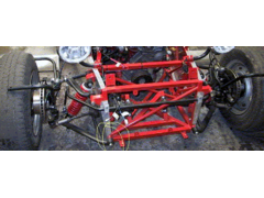
Scrub radius
Ingmar
This is Leitch, origin NZ, also sold in AU.
Rorty
Had a look at the amazing wheel inset? And the amount of scrub radius it has?
Cheers
João
|
|
|
Rorty
|
| posted on 2/3/03 at 01:28 AM |
|
|
Joao:
quote:
Had a look at the amazing wheel inset? And the amount of scrub radius it has?
yes, I moticed that too. It must be around 150mm! 
They obviously feel, being such a light car, it warrants that amount. Either that, or it handles like a
pig!
Cheers, Rorty.
"Faster than a speeding Pullet".
PLEASE DON'T U2U ME IF YOU WANT A QUICK RESPONSE. TRY EMAILING ME INSTEAD!
|
|
|
kingr
|
| posted on 2/3/03 at 11:05 AM |
|
|
I looks like they've put the wheels on backwards! 
Kingr
|
|
|
cymtriks
|
| posted on 2/3/03 at 05:43 PM |
|
|
Leitch chassis
Superb triangulation compared to most kit car chassis if possibly a bit overweight. The lower wishbone of the Leitch, and Caterham, appear to be in
single shear mounts. The lower wishbones carry roughly double the loads of the upper wishbones so if it's OK for the lower ones it should be good
enough all over.
|
|
|
jcduroc
|
| posted on 2/3/03 at 06:47 PM |
|
|
Who are they kidding?!...
quote:
Originally posted by kingr
I looks like they've put the wheels on backwards!
Kingr
Judging from the cycleguards stays it seems so!...
João
|
|
|
Rorty
|
| posted on 3/3/03 at 05:42 AM |
|
|
I think it's time we put this joke to bed, and stop mucking about, in case someone sees that pic of the Leitch, and reads this thread, thinking it is
alright to build their car with that amount of offset/scrub radius.
THEY HAVE DEFINITELY PUT THE WHEEL ON BACKWARDS for clarity, when they wanted to show off their suspension.

Cheers, Rorty.
"Faster than a speeding Pullet".
PLEASE DON'T U2U ME IF YOU WANT A QUICK RESPONSE. TRY EMAILING ME INSTEAD!
|
|
|
Duncan
|
| posted on 3/3/03 at 08:33 PM |
|
|
If you look closely at the wheel on the right side of the picture you can clearly see it is on the wrong way round.
Maybe its time to put this whole post to bed?
I think all that can be said, has been said, although no doubt one of you will have something else to say?
Any of you guys know anyone who would like to earn an extra £50 - £250 per week, full or part time?
|
|
|
craig1410
|
| posted on 5/3/03 at 12:23 AM |
|
|
Hi,
Must be one of the longest threads in history...but there was a point to it once which is why I've just read through it, trying to find the
answer!
Question I have is regarding the orientation of tubes LA and LB. I have welded them so that the front faces of LA and LB are parallel to the lateral
axis of the car. (ie. Front faces of tubes LA and LB in same plane)
However, that means that, due to the inclination of the front assembly, the outside faces (where suspension upper front mounts attach) of LA and LB
are not parallel to the longitudinal axis of the car which seems wrong to me because the suspension mounting will then not be in line with the
longitudinal axis either. I'm sure I could pack out the bracket to suit but surely that can't be right either.
Basically I can't see how the front face can be parallel to the lateral axis and the side face parallel to the longitudinal axis at the same time
with an inclined front subassembly.
Which way should it be aligned? The book doesn't seem to be very concerned about this and the pictures are inconclusive.
Thanks for any help you guys can give,
Craig.
|
|
|
davef
|
| posted on 5/3/03 at 06:32 AM |
|
|
Hi Craig do yourself a favour and fit and tack weld LA&LB in situ on chassis, it,s a lot easier & do as i suggested to Hornet.
take 25mm out of the top tubes & lean LA&LB further back for a more favourable positioning of front top wishbone brkts. also when positioning LA &LB
place a straight edge on the outside plane & measure equally from the straight edge to your marked centre line which your chassis must be set to. that
way you know your brkts will be in the correct plane.also leave FU1&FU2 out untill your front top brkt is set along with the bottom brkts. to make it
easier get youself two pieces of MDF and mark out the configuration on page 63 doubling the horizontal measurments of course, now drill out the marked
out holes to the size of bolts you are using, get four lenghths of threaded bar the same size, and numerous nuts to position all the brkts , and offer
this to the chassis. when all is set, you can now place FU1&FU2 against the top rear brkt which is being positioned by the top front brkt held togther
with the threaded bar having removed the lower threaded bar. i hope all this makes sense to you, anyway it,s how i did mine, cheers davef.
|
|
|
craig1410
|
| posted on 5/3/03 at 07:54 PM |
|
|
Hi Dave,
Thanks for the tips. You have confirmed my suspision that it is the edge plane that should be parallel to centreline rather than the front plane
parallel to the lateral axis. Looks like I'll have to go and cut out my tack welds and make a fw adjustments. I wish the book made this point clearer
because it seems to me that this is fairly important!
Cheers,
Craig.
|
|
|