Nisseven
|
| posted on 18/10/05 at 10:32 AM |

|
|
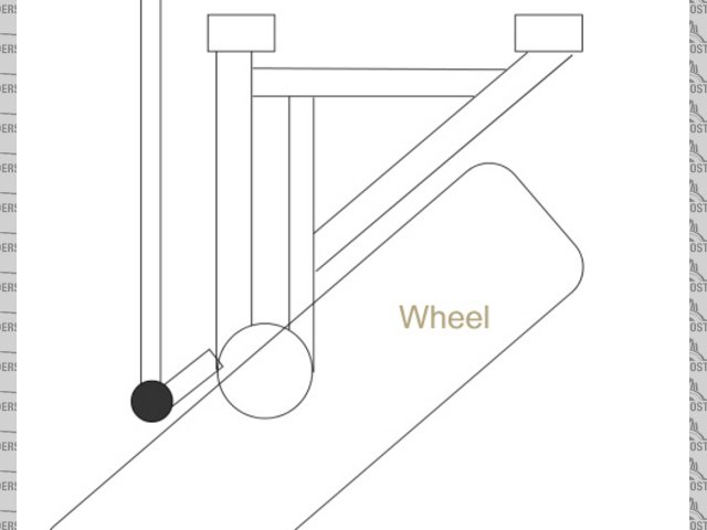
Lower wishbone and steering lock
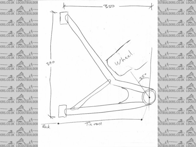
My steering rack is rear mounted and very low, in fact in the same plane as the lower wishbone. As a result I need to run the rack behind the wishbone
and the wishbone has a short rear arm and a long front arm. The donor car ran 35deg lock (from straight ahead) and due to the large offset on my
wheels I can probably only get 25deg with a straight front arm before the wheel fouls it. I can put a bend in the front arm and brace it back from the
bend to the inner end of the rear arm which will be just as strong and not disimilar to the donor car. Only thing it looks a bit silly. I could reduce
the bend in the arm by reducing the steering lock so does anyone have any sugestions on how much lock is to little?
Attached is a rough sketch. Has anyone done anything like this?
Do you think that it would look wrong?
The outer ball joint is a press in one from the donor which was a Nissan Silvia
Bruce Kelly
Rescued attachment scan0002.jpg
|
|
|
|
|
Peteff
|
| posted on 18/10/05 at 11:00 AM |
|
|
Personally
I'd do it like this but it would take more metal and time. I would keep as much of the original lock as possible, it may come in handy some time.
I couldn't see where your wheel was coming from in your picture as it looked like it was crashing into your wishbone from another
vehicle.
Rescued attachment wishbone.jpg
yours, Pete
I went into the RSPCA office the other day. It was so small you could hardly swing a cat in there.
|
|
|
silex
|
| posted on 18/10/05 at 12:01 PM |
|
|
Nisseven,
I have used a similar design in the past. The only addition is a stube welded in parallel to the tw pivots (shown on Peteff's design) as this
will help prevent any spread under braking, etc.
Peteff, one problem with yours is there is no support between the two parallel section. As the rear angled stay joins 3/4 of the way up, the parallel
tubes could easily bend and fail.
Murphy's 2 laws
1. If it can go wrong it will
2. In case of emergency - refer to rule 1.
|
|
|
Peteff
|
| posted on 18/10/05 at 03:11 PM |
|
|
It was only a rough sketch and what you call the front is actually the back as he says he is using rear steer hubs. There would be a joining piece of
plate between the parallel tubes for the shock absorber mount. If you choose the right materials they will not bend "easily" at
all.
[Edited on 18/10/05 by Peteff]
yours, Pete
I went into the RSPCA office the other day. It was so small you could hardly swing a cat in there.
|
|
|
JoelP
|
| posted on 18/10/05 at 07:03 PM |
|
|
this is how id do it. To me it seems a lot simpler, unless your chassis is already braced up for the original mountings. I personally intend to do
this soon, i will use a transit draglink as a lower b/j, i know what everyone says about them, but i intend to destruction test it before i do it.
This would allow you to use a simpler mounting. Also inboard shocks to clear up the area.
I like the idea of having a straight front leg and 'trailing' real leg as it enables a larger wheelbase for the same amount of chassis,
and breaking forces are sent back into the chassis more efficiently.
Mine will also be 'hinged' together to allow more freedom between them, and be rose jointed.
Beware! Bourettes is binfectious.
|
|
|
Nisseven
|
| posted on 20/10/05 at 09:10 AM |
|
|
Thanks guys for your sugestions and sorry that he picture is a bit rough. The wheel is meant to represent a cross section of the tyre and rim at full
lock and yes the steering arms are at the rear. The bottom pivot is about 60mm inside the line of the tyre/rim which means that the odd shape will not
be as visible. The wheelbase would be roughly the same but the suspension pivots will move forward a little and my nose may have to be a little longer
to accomodate this. We will worry about this when the time comes.
Bruce Kelly
|
|
|
NS Dev
|
| posted on 20/10/05 at 02:20 PM |
|
|
quote:
Originally posted by JoelP
this is how id do it. To me it seems a lot simpler, unless your chassis is already braced up for the original mountings. I personally intend to do
this soon, i will use a transit draglink as a lower b/j, i know what everyone says about them, but i intend to destruction test it before i do it.
This would allow you to use a simpler mounting. Also inboard shocks to clear up the area.
I like the idea of having a straight front leg and 'trailing' real leg as it enables a larger wheelbase for the same amount of chassis,
and breaking forces are sent back into the chassis more efficiently.
Mine will also be 'hinged' together to allow more freedom between them, and be rose jointed.
I know I still haven't come back to you with that steering lock angle, will do soon when I actually get in the garage and remember at the same
time!!
As I have said, I use transit balljoints top and bottom with no problems. My grasser doesn't do many miles but they are all extremely hard on
the balljoints so I think they should be fairly well tested!
|
|
|
JoelP
|
| posted on 20/10/05 at 06:35 PM |
|
|
quote:
Originally posted by Nisseven
and yes the steering arms are at the rear
er... thats confused me. You mean that the sloping bone is pointing forward? Why would you do this?!
ns dev, theres no rush for that picture - its going to be a few months til the garage gets emptied, so i have plenty of time to experiment 
Beware! Bourettes is binfectious.
|
|
|
Nisseven
|
| posted on 22/10/05 at 11:07 AM |
|
|
Because I have a rear steer upright and rack. ie. the rack has to be behind the front upright. The line of the rack is at the same level as the bottom
wishbone which means that it does not have room to clear the wishbone and therefor has to be outside it. Hence the rear member has to be at a right
angle with the front member sloping forward. You would like to do it the other way round which is your call but if you were using wheels with the same
offset I have you would strike the same problem except in reverse. In my view the wishbone is stronger with a longer front leg as this is the one
usually loaded in tension, whilst the shorter rear is loaded in compression and I'm thinking of under heavy braking here. A tube is much
stronger in tension than in compression, which is also worth remembering when designing your chassis.
Bruce Kelly
|
|
|
JoelP
|
| posted on 25/10/05 at 05:53 PM |
|
|
quote:
Originally posted by Nisseven
In my view the wishbone is stronger with a longer front leg as this is the one usually loaded in tension, whilst the shorter rear is loaded in
compression and I'm thinking of under heavy braking here.
this may well be correct. I too designed mine with braking as the main thought, as this is undoubtedly where it feels most force. However, i chose to
do it the other way round, because with the rear leg aiming back, it is transmitting the braking force more directly into the chassis.
With your setup, you could probably use a thinner wall tubing for the wishbone, but i believe the front of your chassis would experience more stress.
It would obviously be interesting to see both finished, and see how different the chassis ended up.
Beware! Bourettes is binfectious.
|
|
|
NS Dev
|
| posted on 25/10/05 at 09:47 PM |
|
|
pics of grasser steering as promised finally!!!
 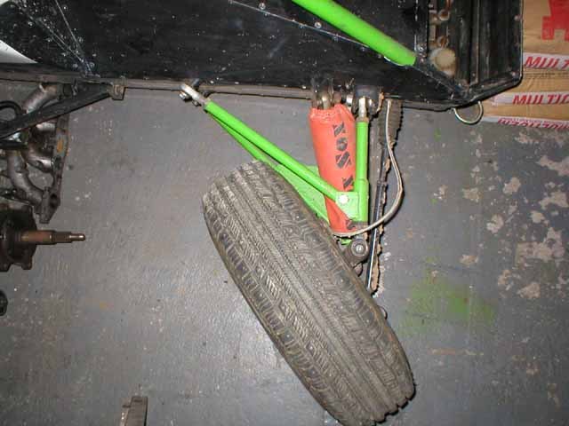
grassersteer1
 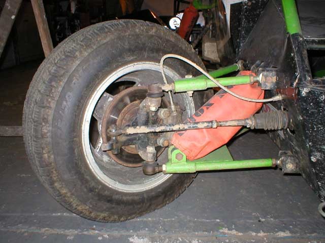
grassersteer2
 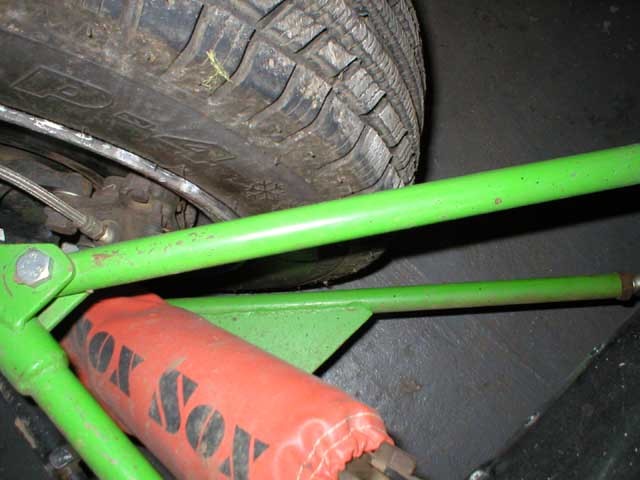
grassersteer3
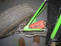 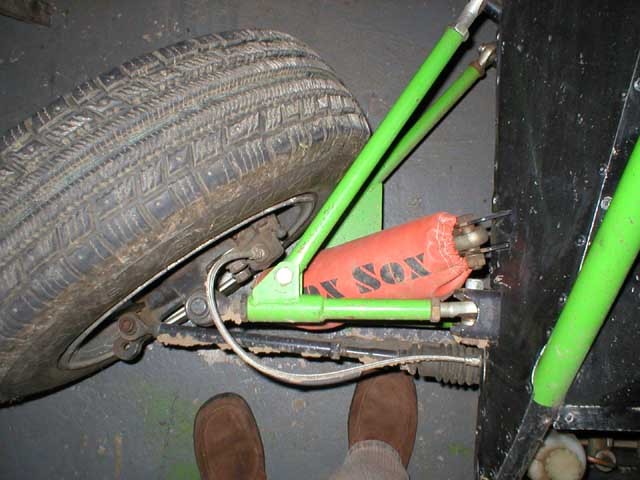
grassersteer4
|
|
|
NS Dev
|
| posted on 25/10/05 at 09:49 PM |
|
|
as you can see, no need to worry about not having enough steering lock!!
Note the modded steering arm on the Cortina uprights, to get more ackerman and more lock per mm of rack movement. Also note the use of transit
draglink ends top and bottom!
Its fun on tarmac when you have that much each way and only 3/4 of a turn on the steering wheel from lock to lock..................great for sliding
about funnily enough!!!!
[Edited on 25/10/05 by NS Dev]
|
|
|
JoelP
|
| posted on 25/10/05 at 10:24 PM |
|
|
awesome nat, cheers for that
is the lower cortina taper correct 'as is' or did it need changing for the transit rodend?
Beware! Bourettes is binfectious.
|
|
|
NS Dev
|
| posted on 25/10/05 at 10:25 PM |
|
|
99.9% sure it was right already, but I did build it 3 years ago now!!!
I'm almost certain the tapers are the same top and bottom.
|
|
|
NS Dev
|
| posted on 25/10/05 at 10:30 PM |
|
|
If you are wondering what the hell the brakes are, don't worry they are no good for road use, they barely work!
They are "modified" (sounds technical, I can assure you it wasn't!!) astra GTE rear calipers on machined down cortina discs.
Why.............cos I found them in a pile of junk at the back of the garage and they didn't weigh much!
|
|
|
JoelP
|
| posted on 26/10/05 at 05:29 PM |
|
|
lol ive got an awful pile of crap at the back of the garage, wish any of it was useful!
Beware! Bourettes is binfectious.
|
|
|