907
|
| posted on 6/5/06 at 11:26 AM |

|
|
Fuel gauge voltage reducer
Hi All, electrical dimwit here.
As you can see from the pic below I have two of these.
When fitted and wired to the fuel gauge one reads below the red, to 3/4's full,
and the other one reads 1/4, to past the Full mark, depending on tank sender position.
I think I'm right in thinking that they reduce 13 volts (ish) down to 9 or 10v.
When I put an avo on them they actually oscillate between 6 and 11v.
So the question is, can I buy a modern version of these?
Or, could one be made, ideally with some sort of adjustable pot (?) so that the output
voltage could be "tuned" to the fuel gauge reading.
I believe I also have to run the engine temp gauge through this as well, (or use two)
but I haven't wired that yet.
Any advise would be much appreciated, on either where to buy or how to make,
but please, keep it simple. 
Cheers
Paul G
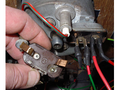 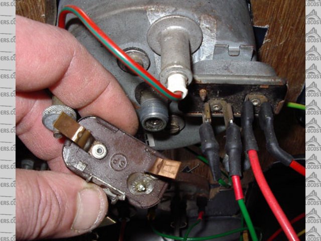
Rescued attachment volt-reg-s.jpg
|
|
|
|
|
rayward
|
| posted on 6/5/06 at 11:41 AM |
|
|
HI,
pretty sure thats a voltage regulator, not a reducer.
have a look at the link below, may help
Fuel sender info
Ray
|
|
|
Bob C
|
| posted on 6/5/06 at 12:08 PM |
|
|
Yep - they're horrible things that regulate and reduce the average output volts to about 9. They use an internal heated bimetal strip thing
& switch on & off to get the average volts right. It's likely (though I'm not sure) that because the guages are often thermal
bimetal strip things, the thermal voltage regulation makes the guages read right at high/low cabin temperatures.
You could replace 'em with a 3 terminal regulator (317 type thing) but if you got the gauges & regulator as a set I'd let sleeping
dogs lie & use it as originally intended!
Bob
|
|
|
rusty nuts
|
| posted on 6/5/06 at 12:25 PM |
|
|
Looks like the old Lucas voltage stabiliser , can't help with a modern unit though. Did you get one that came with the gauges? probably pay to
use that one? Also is fuel tank sender the one that matches the gauge?
|
|
|
907
|
| posted on 6/5/06 at 03:35 PM |
|
|
Hi again,
I picked up the gauges at various shows and auto jumbles.
They are not a set and I haven't got matching senders, although they are all Smiths
and the tank sender is from an Escort.
I like them, and don't really want to replace them with modern equivalents.
What do you think. (see pic)
It's just the regulators. One I was given, the other was mounted on the speedo
where it is now. If one or other gave a fraction higher or lower output the gauge
would read spot on, or can you move the needle round?
What's a 317 Bob?
Many thanks for your replies so far, and sorry to be a pain.
I'm not good with electrics.
I should stick to welders, nice & simple, a + one end and a - at the other,
and some sparks in the middle. 
Thanks
Paul G
 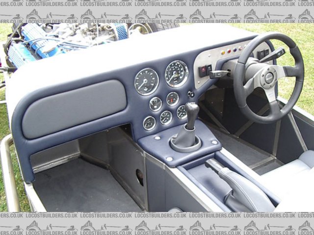
Rescued attachment dash-gauges-s.jpg
|
|
|
David Jenkins
|
| posted on 6/5/06 at 04:19 PM |
|
|
Paul,
I can help you out with these electronic voltage regulator gizmos - I've used dozens of the things over the years. Totally painless, and very
reliable as long as you don't overload them or let them get too hot. All we really need to know is what current each instrument takes and what
voltage it likes, then I can work out a circuit for you.
Send me a U2U to arrange a day and I'll bring over my Maplins catalogue...
cheers,
David
[Edited on 6/5/06 by David Jenkins]
|
|
|
Syd Bridge
|
| posted on 6/5/06 at 05:51 PM |
|
|
G'day,
Those old time volt regs are the spawn of the most evil one. The rf they give out can affect anything digital nearby. I chased an intermittent problem
in our rev limiter for ages, then when the instrument volt reg gave out and was replaced with a modern IC type, problems were all gone.
On the oscilloscope, a similar old thing oscillated between full +volts and about 7+/- volts. Average was about 10~10.2 volts.
Use an adjustable three leg IC from Maplins or similar, and set it up on the resistors for as close to 10volts as you can get. (The resistors I had to
hand gave the 10.2volts.) Add the biggest capacitors you can get in, and make sure they are rated at no more than 16volts, and no less than 12. I
used 16V 4700uFarad, from Maplins.
Cheers,
Syd.
|
|
|
planetester
|
| posted on 6/5/06 at 07:31 PM |
|
|
I copied a web page from the MG website that delt with voltage stabilizers but for some reason is not availiable online any more.
Just found an exact copy on a lotus website, shows how to mack one using I'cs
http://www.lotusenthusiasts.org/Newsletter/V5-10.pdf
[Edited on 6/5/06 by planetester]
|
|
|
Bob C
|
| posted on 6/5/06 at 11:15 PM |
|
|
317 is the generic "adjustable" linear voltage regulator chip (1.25 to about 30V) - a google search for LM317 should reveal all!
cheers
Bob
PS probably worth looking a little harder for an automotive rated equivalent - high temp & 40 odd V capability
|
|
|
907
|
| posted on 7/5/06 at 09:10 AM |
|
|
Well done chaps
Hi, and thanks to all.
Yet another bolt hole cut in the maze that is my wiring loom.
There must be experts on everything on this forum.
Cheers
Paul G
|
|
|
David Jenkins
|
| posted on 7/5/06 at 01:38 PM |
|
|
Folks,
A few questions so that I can help Paul as best as possible:
1. Does each instrument have its own regulator, or do several dials share just one?
2. What's the highest current I need to cater for?
3. What's a typical voltage? (the link above suggests 10v)
Once I know all this I can identify the components required.
Cheers,
David
|
|
|
Syd Bridge
|
| posted on 7/5/06 at 04:58 PM |
|
|
David,
As I pointed out, the oscillator appears to give an averaged 10~10.2 volts on the oscilloscope.
I used a 2amp IC for the temp gauges. One IC for the two.
There is no reason you shouldn't use a separate IC for each instrument. But if total current is less than 2A, then one will obviously do the
job.
I've not got the resistances of the transducers to hand, nor the fuel sender. But I'm sure you could get 907 to give you his senders and
the R's could be measured. You can obviously take it from there by what you've put.
The big capacitors across the input V+ and V-, and output and earth are essential, or were to my specific case at least, to keep everything smooth and
quiet.
Cheers,
Syd
Edit. Forgot to say; The IC needed to be attached to a piece of 4mm flat ali, about 30x50mm (that was as big as would fit in the plastic case the
thing was assembled in), to get the IC cool enough. And that was running with less than 1A current output with 13+ volts input. ( On reflection,
rereading what I've just written, the power dissipation is near 3W, and could be 6W, which is a goodly amount in most small electronics .)
[Edited on 7/5/06 by Syd Bridge]
|
|
|
907
|
| posted on 7/5/06 at 10:32 PM |
|
|
Hi Syd,
I've U2U'd David but the voltage required I'm not to sure of.
There are two gauges that require a regulated voltage, fuel & temp.
I'd go for separate regs, at least if we can get one right the other can be changed without messing up the first.
The gauges are both Smiths but the sender for the engine temp is whatever Lotus fitted.
I could always change it as long as the thread isn't a problem.
Many thanks for all the help everyone.
Cheers
Paul G
|
|
|
David Jenkins
|
| posted on 8/5/06 at 07:14 AM |
|
|
Paul,
If we use 2 variable regs then we can always fiddle with resistor values to match each device.
David
|
|
|
02GF74
|
| posted on 8/5/06 at 10:03 AM |
|
|
those things are regulators; as mentioned, a bimetallic strips makes contact so average votlage is about 9 to 10 V.
The fuel/water temp guages used with it are slow repsonse hence you don't see the switching.
you can replace by solid state 1 A regulator.
Beware that mix/matching random guages/senders is not striaght forward.
depends on resitance of the sender and the direction (i.e. whcih was the resistance changes for a fuel gauage)
|
|
|


.jpg)