tom_loughlin
|
| posted on 24/6/06 at 04:29 PM |

|
|
Diodes help....
Hi Guys,
Today I went to get me some diodes and got 1x 1.3W 15v Zener, and 2x 1N4004s diodes.
Ive connected them up the correct way round, but the revotec rev counter still won't work.
I understand the 1N4004s are in series with the coil packs outputs, to stop the current flowing the wrong way, but whats the Zener doing?
Have tried changing the jumpers on the back of the rev counter too, but with no luck.
Below is a diagram of what I've tried...
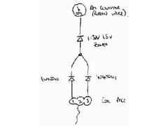 
diodes diagram
Anyone know where I'm going wrong?
Have also tried wiring the tacho directly to pin 2 on the EDIS with no luck...
[Edited on 24/6/06 by tom_loughlin]
|
|
|
|
|
mark chandler
|
| posted on 24/6/06 at 04:46 PM |
|
|
Hi,
I hope when you say coil pack output you do not mean spark ! but actually the feed to the coil pack.
Okay what the diodes do is stop any reverse current, this means that you cannot screw up the spark by pushing volts into the coil pack, you also will
not see any back EMF as the coil discharges abnd throws voltage backwards. The Zener diode is basically a clever diode that will restrict the voltage
as well so makes sure you are not hitting your rev counter with and high volts.
Okay then, are the bands on the diodes all pointing towards the Rev counter ?
You can easily break this down into componants and test.
So just connecting the standard diode, with a meter to earth engine running you should see 12v pulsed on the output, if not its probally reversed or
knackered. Assuming yes then if you put the meter behind the Zenar diode facing the rev counter you should now see pulsed voltage at twice the speed
(it gets two lots of feed from each coil), although this will be regulated to a set voltage, if not the same applies as above.
Regards Mark
|
|
|
paulf
|
| posted on 24/6/06 at 09:32 PM |
|
|
I used tha same method on y rev counter and to get it to work I had to connect a resistor between the output of the zener diode and + 12v, I think I
used a 1k resistor .This pulls the voltage back to 12v in between pulses and worked on a smiths and a ford tacho.
Paul.
quote:
Originally posted by tom_loughlin
Hi Guys,
Today I went to get me some diodes and got 1x 1.3W 15v Zener, and 2x 1N4004s diodes.
Ive connected them up the correct way round, but the revotec rev counter still won't work.
I understand the 1N4004s are in series with the coil packs outputs, to stop the current flowing the wrong way, but whats the Zener doing?
Have tried changing the jumpers on the back of the rev counter too, but with no luck.
Below is a diagram of what I've tried...
diodes diagram
Anyone know where I'm going wrong?
Have also tried wiring the tacho directly to pin 2 on the EDIS with no luck...
[Edited on 24/6/06 by tom_loughlin]
|
|
|
MikeRJ
|
| posted on 25/6/06 at 01:05 PM |
|
|
Reverse the polarity of the zener diode.
It's purpose is to ensure the voltage on the rev counter falls to zero between spark events which it won't do when forwards biased as it
is in the diagram shown.
|
|
|
tom_loughlin
|
| posted on 29/6/06 at 11:45 AM |
|
|
Thanks gents, I tried a resistor (1k) and reversed the zener and all's good now.
I'm now confused, how can any current flow past the Zener, if it's polarity is reversed?
The bands on the two are towards the rev counter, but the Zener band is what appears backwards....
Oh well, it's working now, but I would quite like to understand why...
Thanks again
Tom
|
|
|
David Jenkins
|
| posted on 29/6/06 at 12:00 PM |
|
|
Basic English explanation...
A zener diode will conduct in the forward direction, just like any other diode. In the reverse direction it will block current flow like any other
diode - up to a point, where it starts to conduct. As if by magic, it will maintain this trigger voltage level.
Alternative, slightly more techie explanation HERE
[Edited on 29/6/06 by David Jenkins]
|
|
|
tks
|
| posted on 9/7/06 at 12:50 AM |
|
|
zener
The zener is there to make the 0 pulse with wider...
because when the voltages is dropping and it comes unther the zenervoltage... then the rpm counter reads a 0 this will be until the voltage is riseing
again sow it will make the singal more clean...
if you can use a 12volts zener it will give you a very wide and good signal...
there are also rpm counters that wants to see only a flyback voltage from the coil (on the same line)
then you should use a 24volts zener
it will trigger when the flyback voltage gives the little small pulse..
Tks
The above comments are always meant to be from the above persons perspective.
|
|
|
MikeRJ
|
| posted on 11/7/06 at 07:23 AM |
|
|
quote:
Originally posted by tks
The zener is there to make the 0 pulse with wider...
It's not so much to alter the width of the pulse, it's to ensure the voltage drops down to zero volts between igntion events. Because
there are two paths to the 12v ignition source, without the zener there will always be at least 12 volts at the tachometer, and most of them
won't work.
|
|
|
MikeR
|
| posted on 11/7/06 at 09:49 PM |
|
|
so could someone read off the parts as i can't read the images well enough to add them to my maplin shopping list.
cheers, mike
|
|
|
02GF74
|
| posted on 12/7/06 at 10:56 AM |
|
|
quote:
Originally posted by MikeR
so could someone read off the parts as i can't read the images well enough to add them to my maplin shopping list.
cheers, mike
err....he lists them at the top, the bit with all the words. 
got 1x 1.3W 15v Zener, and 2x 1N4004s diodes.
so 1N4004 and whatever maplins show as the zener.
|
|
|
MikeR
|
| posted on 12/7/06 at 01:15 PM |
|
|
[cough]
when'd he edit that 
[cough]
ooops! thanks, having read the first bit when it was first posted, i've just followed the bottom of the thread when it was added too.......
|
|
|
tks
|
| posted on 13/7/06 at 06:17 AM |
|
|
quote:
Originally posted by MikeRJ
Reverse the polarity of the zener diode.
It's purpose is to ensure the voltage on the rev counter falls to zero between spark events which it won't do when forwards biased as it
is in the diagram shown.
The resistance you added is a pulldown resistance, it will make sure the pin is never floating. always use high values for this resistor, else there
is allot of current needed to pull it down.
the zener is there to make the 0pulse wider and to make it nicer. the coil will be during 11miliseconds 0 (dwell time) with the zener it will be seen
as more time 0.
Anyway it works.
The above comments are always meant to be from the above persons perspective.
|
|
|
MikeRJ
|
| posted on 17/7/06 at 09:17 AM |
|
|
quote:
Originally posted by tks
the zener is there to make the 0pulse wider and to make it nicer. the coil will be during 11miliseconds 0 (dwell time) with the zener it will be seen
as more time 0.
Anyway it works.
No, have a look at the schematic. There are two coils, both with a common connection that goes to +12v. Only one coil is ever grounded at a time, so
with just the 1N4004 diodes there will always be at least +12v at the tachometer (to be exact, 0.6 volts less than the coil supply and with ~300volts
pulses on top whenever a coil fires). Most tacho's need to see a signal that gets close to 0v. By adding the zener you get rid of this +12v
offset.
[Edited on 17/7/06 by MikeRJ]
|
|
|


.jpg)