Pavs
|
| posted on 3/2/08 at 07:22 AM |

|
|
3d design of mid-BEC
Hi everyone, I've been reading these forums for ages now, and just now decided to register!
I'm in uni and have been involved in the Formula Student team's race car, and being a bit of a car nut (as you have to be to be on here!),
I've decided to start designing my own road/kit car.
At this point i'd like to point out that i'm not intending on building this within any immediate future, although if all goes well I'll
begin sourcing stuff and who knows!
Secondly, I am no engineer (study geography!), so excuse my incompetence at using stuff like SolidWorks since i've never had any training in
it!
Here's the general idea of the car:
Steel tube/square spaceframe with integrated tube roll bar
Mid engined,
Powered by a low-pressure turbo'd Hayabusa (looking for approx 220-250 reliable bhp).
Quaiffe ATB for BEC diff driven by chain. (no plans for reverse at the moment since i havent really done research into the available options).
Pedal clutch used for stop/starting, electronic shifter for clutchless up and downshifts (so no need to use the pedal while driving).
Now all of that isn't anything particularly novel, so here are the ideas that i'm trying to incorporate into this car:
Carbon fibre suspension arms. The way these will be made is from approx 30mm carbon tube (which isn't all that expensive actually!). The ends are
aluminium alloy plugs, which extend a couple of inches into the carbon tube, and are glued in place. The alloy plugs are then tapped in the middle to
accept rose joints (at the moment all are 3/8" but I think I'll have to step this up in size!)
Suspension-arm-activated pushrod system. This basically means that one of the suspension arms, instead of simply an alloy plug on the inboard end will
have a complete extension to go under the chassis rail and inboard to act on a (almost) vertical pushrod.
The shocks will be mounted longitudinally in the car, and at the BOTTOM extending from the pushrod towards the driver and centreline of car. If
anybody has any real-car references (I've only seen inboard shocks mounted in the middle or at the top) to systems like this I'd love to see
them. TO me it makes lots of sense in that it brings the CG quite a bit downwards! Hoping to get some of those remotely adjustable units!! The rear
shock setup hasn't yet been designed but is likely to be similar, although possibly the shocks will be further apart (away from the
centreline).
All round inboard brakes. At the back this will be achieved by a sprocket/brake rotor (sprotor?), on which a single caliper will be installed for
braking, and a small spot caliper for handbrake. There shouldn't be much need for a lot of braking force in the back of this thing, but this
might be inadequate in which case I'll mount a second disc with a second caliper. The discs will be solid incidentally and the width will be
dictated by the chain drive.
The front will also have inboard brakes. A central hub running in three 32/55/13mm sealed ball bearings will have two vented 13" brake rotors
attached to it. The bearing carriers and callipers will be mounted to chassis rails running longitudinally. The ends of the hub will have a simply
6-bolt flange to attach to a driveshaft.
All driveshafts (front and rear) will be carbon fibre (http://www.pstds.com/critical_link_drive_shafts.htm). This should offset the weight increase of
using inboard front brakes with driveshafts.
The uprights will be aluminium alloy, the drive flange/hub will be steel with splines to accept the driveshaft end, then secured with a hub nut (the
bearing configuration/mating of hub to upright isn't finalised so if you have any input, i'm all ears!) The idea at the moment is to use
identical hubs/uprights front and rear which would be quite good in terms of production. Since both would have driveshafts in them and the rear toe
will be controlled by a fixed link that'll be identical in construction to the front steering links.
The next thing I'd like to play around with is carbon fibre wheels. At the moment the car is designed with 16" wheels and i'd like to
keep them around that size (maybe 15"? the problem with 16's is less tyre choice, but there are semi slicks in 225/35/16 by toyo and
yokohama so not too worried about that. Plus that way ther's still scope for using them with outboard braking systems).
The way the carbon wheel design is is 5 piece (yes a 5 piece wheel). 2 spun 3mm aluminium rims as standard on all split wheels. To this is attached a
10mm thick carbon plate with the spoke design cut out of it. However, this has a centre hole of approx 140mm diameter, into which from both sides
alloy "centre" sections clamp the carbon plate (with bolts going through it). The idea behind this is that the bit actually attaching to the
hub will be alloy rather than carbon fibre, and the wheel nuts/bolts will be clamping into an alloy rather than risking damaging the carbon fibre
expoxy.
The nosecone of the car (no design yet) will have openings at the top through which the calipers will stick out (that could look really cool!), and at
the bottom will extend to just past the shock mounts where the chassis becomes flat (the front and rear suspension boxes are slighly jacked up
compared to the middle section of the chassis).
From there on (the cockpit section) there will be a flat sheet of carbon fibre attached to the bottom of the car, hopefully getting some ground
effects downforce.
No provision for windscreen or roof, just an aeroscreen.
The radiator will be mounted to one side (although not in a pod protruding to the side because there is only about 20cm difference between width of
cockpit and total width to the edge of the wheels.
The intercooler will be a similar size, probably square-ish, and mounted symmetrically on the other side. Both will have some serious ducting leading
to them since they won't be in very direct airflow.
At the moment I'm contemplating mounting the fuel tank longitudinally in the cockpit between driver and passenger since there is no transmission
tunnel or anything and tha's a very nice space, but I may be sensible and not do that for safety's sake (and instead mount it next to the
engine which is the only other available space! :p )
Incidentally the size of the car is approx the size of a first generation Mercedes SLK (its rough dimensions were used for the inital layout of
chassis). From the bottom of the chassis to the top of the roll bar is 90cm.
The steering rack will be mounted quite far forward but still rear-steer and at the moment looks like it'll be approx 52cm from tip to tip (where
it'll join the steering arms that go to the hubs. the steering arms will also be carbon fibre, same as suspension arms).
Right if anybody actually was bored enough to read to this point, thank you! :p Any input or criticism very welcome. remember the idea behind this is
innovation!!
I have Solidworks models that I'm glad to share with people if they want to play around with it or just get a better idea of what I was rambling
on about!
Incidentally the ball shaped things in the pictures are because I couldn't model the rose joints, so they're basically representing rose
jointed connections! (and the cones are the mountings for the rose joints!)... still not an expert with CAD :p
Pavel
 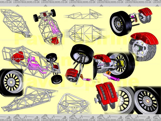
Rescued attachment model.jpg
|
|
|
|
|
Ivan
|
| posted on 3/2/08 at 08:09 AM |
|
|
I love the innovation of your design but have a few concerns.
- The front appears way overbraked from your sketch - I doubt that anything that light will need the size callipers and discs that you show - I think
this is an ideal application for bike discs.
- I would worry about putting canterlevered forces through the carbon fibre arms
- Love the wheels but testing them for durability will be a problem.
- With unsprung weight being such a priority I wonder why you don't go for 13" wheels where there is a large selection of track type
tyres and significant weight savings to be had.
- Much of what you plan is relatively untried for road going cars so you are putting a huge development load on yourself.
I very much look forward to your progress with this design. Please keep us updated.
|
|
|
Pavs
|
| posted on 3/2/08 at 08:39 AM |
|
|
1. Yeah, the front is way over braked at the moment, the reason being that I already had the calipers and discs modelled from before so just used
those, but the actual ones used will be smaller (although I still think I'll be using vented car discs rather than bike ones since the inboard
mounting means that the discs will heat up quite substantially!)
2. The arm that is acting on the pushrod will have a 5mm thick aluminium extrusion throughout its entire length, and a solid aluminium bung on the
cantilever end of approx 2.5" length. (it's almost a completely metal alloy arm, just with a carbon tube wrapped around it).
3. & 4. Yeah at the moment the wheels are just an idea until I talk to some composite specialists. I know that carbon wheels are used on light
stuff (even formula student use them, but the whole car weighs approx 200kg). I don't see why it would be a problem, particularly given the
thickness I intend to use. As for the wheel size, I also thought of using smaller wheels. However, since the centre section is carbon fibre (and the
alloy bit is a fixed size due to stud mounting size), the difference from 13" to 16" is in the order of 500-600 grams, which I think is
less than the equivalent change in tyre sidewall! As it is each wheel weighs approx 4.5 kg which is very light from what I can tell for a 16"
wheel.
5. That's the main reason behind this whole project, to see if there's something new that can be utilised for fast road cars!
Thanks so much for the input,
Pavel
P.S (Just realised that my braking hub is one piece and thus is effectively a solid diff. Will split it in half and add a 4th bearing (so
there's a hub for each wheel spinning in 2 bearings so the two front wheels arent connected to each other!)
|
|
|
Ivan
|
| posted on 3/2/08 at 09:11 AM |
|
|
I would have thought that one of the advantages of the front inboard mounted discs would be that you can get much more air to them than if wheel
mounted but guess theres something I'm not aware of.
re the 13" wheels I think the big weight saving will be in tyre weights not necessarily the wheel weights.
|
|
|
tegwin
|
| posted on 3/2/08 at 10:05 AM |
|
|
Pretty cool project..
Im not convinced you can really use the suspension arms as rockers, i thought CF didnt work very well in torsional shear....It would be ok in pure
compression or tension, but wont if just crack under the shear loads you are talking about with the rocker suspension?
But someone has already mentioned that so you can just ignore my rantings!
[Edited on 3/2/08 by tegwin]
|
|
|
CurlyBen
|
| posted on 3/2/08 at 10:29 AM |
|
|
If I were you I'd do some research on corrosion between ally and CF. I can't really remember the ins and outs of it but certainly
it's an issue in boats. You really wouldn't want to have the ally parts of the suspension arms quietly corroding out of sight! By the way,
carbon fibre's strength is in tension. In compression you may as well just be using resin - in fact I think the CF will weaken the
matrix's properties. Transverse loading gives you essentially the properties of the matrix - carbon/epoxy has a transverse tensile strength of
about 3% of the longitudinal tensile strength. You may be able to get away with it if you lay it the right way but I'm not an expert. I should
probably add that I've not built a car yet, I'm about to start planning one to start in a year or two, but I've had some lectures on
CF and know a bit about the properties, but not how to design with the stuff.
Looks like a cool project though!
Cheers
Ben
Edit: meant to say I think it's galvanic corrosion you'll have a problem with between ally and CF, so you should be able to solve that by
insulating it in some way.
[Edited on 3/2/08 by CurlyBen]
|
|
|
Pavs
|
| posted on 3/2/08 at 10:56 AM |
|
|
I have definitely read that people have used CF bonded to ally without any problems.. I would've thought that the epoxy+glue would prevent any
potential corrosion?
As for the application of carbon tubes for suspension arms... F1 use them.. furthermore rowing blades (oars) are made of carbon fibre tubing and are
about 2.5" OD, and 4 meteres long and I've yet to see one snap. The great thing about carbon tubing is that depending on the layout and
configuration of the fibers the tube can be constructed for a specific job. The only problem with them would be the loading that the cantilever arm
would experience, and for that very reason a 5/6/7mm thick aluminium extrusion inserted into the tube should provide the necessary stiffness. The
cantilever end itself will be machined out of ally (or even titanium?) and at around 1" thick should be adequate.
|
|
|
nitram38
|
| posted on 3/2/08 at 11:24 AM |
|
|
F1 carbon wishbones might be strong, but for road use they wouldn't last that long. These things are replaced after everyrace. You also
mentioned a 5mm thick aluminium core. Better make than 10mm as 5mm will bend easily.
Inboard brakes will require strong CV joints on any driveshafts, plus you are adding the weight of the driveshaft to the wheels and car.
F1 tried inboard discs, but have reverted to conventional wheels.....you have to wonder why.
Using lighter brake materials is the way to go.
Trying radical designs on paper is easy, building and more importantly, paying for them is not!
I recommend keeping your designs on paper and start checking out some of the cars at shows like goodwood etc.
That way you will get a better feel for the practical side and understand the history and evolution.
Sorry if I am sounding harse, but you could waste a lot of time and money going this route and I am trying to give you a balanced view.
|
|
|
CurlyBen
|
| posted on 3/2/08 at 11:48 AM |
|
|
quote:
Originally posted by Pavs
I have definitely read that people have used CF bonded to ally without any problems.. I would've thought that the epoxy+glue would prevent any
potential corrosion?
As for the application of carbon tubes for suspension arms... F1 use them.. furthermore rowing blades (oars) are made of carbon fibre tubing and are
about 2.5" OD, and 4 meteres long and I've yet to see one snap. The great thing about carbon tubing is that depending on the layout and
configuration of the fibers the tube can be constructed for a specific job. The only problem with them would be the loading that the cantilever arm
would experience, and for that very reason a 5/6/7mm thick aluminium extrusion inserted into the tube should provide the necessary stiffness. The
cantilever end itself will be machined out of ally (or even titanium?) and at around 1" thick should be adequate.
Have a look at this document (link)
It mentions the problems of corrosion there - one solution I've heard of is to use a wrap of fibreglass between the carbon and the metal. I
wasn't trying to suggest you can't use aluminium and CF together but you need to research it properly - if a suspension arm fails
it's not exactly a minor thing. As for long carbon tubes, I've got a mast which is probably 7metres or a little more, and is maybe
4" in diameter at the plug. I've seen plenty of them break but more importantly they also bend a hell of a lot. As I said I don't
know a huge amount about how to design with carbon, and I'm not trying to suggest what you're thinking about can't be done, but
there's much more to it than just deciding the shape and grabbing the first weave you can find and slapping some epoxy on! Talking of which
epoxy is the glue (also known as the resin or the matrix - others, such as polyester, are available, but probably not as suitable for this
application) and it won't insulate the carbon sufficiently on its own. All the ally fixings on my mast are drowned in silicone to isolate them,
and they're mainly on top of the lacquer as well.
[Edited on 3/2/08 by CurlyBen]
|
|
|
Wolf HR
|
| posted on 3/2/08 at 12:11 PM |
|
|
Another thing I'd consider about suspension is that when CF wishbone fails- it shatters (and the part is no more), whereas metals will usually
bend, but will temporarily retain some of it' function. I think it's quite important safety-wise: say, one hits a kerb or a pothole at
speed and damages suspension arm. With metal suspensions, you'll get in trouble but will probably be able to limp to safety with bent suspension
ar, whereas with CF one is in lot of trouble and will end up stranded on the spot... Same goes for the wheels.
Inboard brakes (as Nitram has pointed out for F1) is rather contentou principle. But, as you're probably already aware- Mercedes W196 won two
back-to-back titles with them. There will be more weight added to the car, and reduced unsprung weight, which should improve handling. Keeping hot
disks away from tyre might not be so important for a road car, and you'll probably have to give cooling ducts a lot of thought to ensure
sufficient cooling. ISTR inboard brakes have been successfuly implememted (for driven wheels) on road cars.
SILLY IDEA WARNING Have you considered what would be implications in terms of handling, since you'd already use halfshafts on front wheels, of
adding a LSD between them? If one used adjustable (Salisbury type), I imagine fiddling with it would allow one few easy setup adjustments...
But it's a daring concept, and I like it. I'll keep my fingers crossed for your success. HTH
|
|
|
kikiturbo
|
| posted on 3/2/08 at 02:55 PM |
|
|
honda experimented, and was dissalowed from using an LSD diff in the front, to balance the front braking on conrner entry...
as for the project... I also wanted to use horisontal pushrod operated shocks on mine, but the verry narrow space between the front lower wishbone
mountings would make the pullrod geometry very bad, and would mean less space for my feet..
|
|
|
Pavs
|
| posted on 3/2/08 at 03:37 PM |
|
|
now that is actually very interesting!
fitting an lsd instead of dual brake hubs wouldn't really increase weight by any signicant amount. That way I could have one brake rotor
(probably the size that is modelled on there now) with one brake caliper with the rotor attached to the LSD as a sprocket would be. Not only will that
give a rather interesting way of tuning corner braking (i'd imagine this is as close to ideal as you can get without electronics), but it would
actually be a more compact package than i have now!
By cantilevering off the rearmost top suspension arm I've basically bypassed the problem you describe of packaging issues between the front
wishbone mounts, since the shocks are mounted further back. Also by mounting both shocks closer to the centreline of the car, that means that further
back (where the pedal box would go) you get more space for your feet (and the shocks are mounted almost as low as the lowest chassis rail (ALMOST the
lowest point of the car but not quite), so they dont protrude into the space vertically as much.
Thanks to everyone for their input, nitram i am very aware that a lot of these things are possibly undesirable, or impractical, but at the moment
they're all being considered simply because it would be a shame to dismiss something just because its unconventional. Having said that, I will
gladly replace/redesign components if through later stages it becomes clear that there are better ways around it.
Wolf, you make a very good point about the suspension arm failure! I see two options to try and remedy this. One is to insert a thin walled aluminium
tube into the carbon arm and glue the aluminium endcaps into the tube itself. This was the original idea, since the aluminium will allow the arm to
absorb any severe shock loads, and hopefully last long enough after a failure to bring the car to a halt. The other option is to cable the front
upright to the chassis... that of course would mean that in an event of a failure you still end up with a car-sled as the wheel will just dangle by
the cable.
I'm not sure on how quickly all the components (suspension arms) would fail if one did? because if a suspension arm was to effectively
disintegrate (I understand there's very little "in-between state" with carbon tubing between normal and broken!), it would be highly
visible since the suspension arms are on display all the time.
The weight issue of adding driveshafts to the front isn't a major concern of mine. Firstly all 4 driveshafts will be carbon fibre which will a)
put more weight forward since I have two more driveshafts b) remove weight from the back since they're about half the weight of conventional
driveshafts. Yes it'll add about 5 kilos (a bit more with a LSD) of weight to the car, but it'll add it in the front where it'll
help the overall weight balance. Also consider how much unsprung weight it will REMOVE from the front suspension.
|
|
|
Wolf HR
|
| posted on 3/2/08 at 04:19 PM |
|
|
Pavs- a single differential brake would be a bit handful to experiment with. It was tried even in F1 (beautiful B.R.M. Type 25 and it's
successor P48, IIRC). and I don't think a good word was spoken about it (mostly because of severe overheating it suffered).
Safety wise, two smaller brake discs would be a safer option- in case of single disc on diff a failure would mean a total loss o f braking capability
on the front end, whereas with one on each halfshaft, should one fail, the other will partially take it's function.
Third consideration would be whether it would be 'street-legal'. AFAIK in my neck of woods, regulations state that a vehicle must have a
brake on/for each wheel, and it would be worth checking out how things stand where you live.
|
|
|
Pavs
|
| posted on 3/2/08 at 04:55 PM |
|
|
I must be missing something then... surely if there is a disc on each halfshaft, the differential would play absolutely no role whatsoever? Whereas a
torquebiasing lsd with a single brake attached to it could distribute braking force to the wheel with maximum grip and hence prevent locking of the
unloaded wheel?
I wasn't aware of the regulation regarding a brake for each wheel, I was totally under the naive impression that you could run a single inboard
brake on rear BEC setups! Will have to look into this.
Pavel
|
|
|
Wolf HR
|
| posted on 3/2/08 at 05:43 PM |
|
|
I think there would be interaction between halfshafts- same as on rear end where there are separate settings for power and coast (i.e.
braking) on adjustable Salisbury diff... In front one would be able only to adjust locking ratio on coast...
Off top of my head, I would venture a guess that more lock would introduce understeering tendency on corner entry when trailbraking (or reduce
oversteering tendency), and add some stability in straight-line braking.
EDIT- another thing to illustrate would be one wheel locking up- with LSD, it would lock more and the running wheel would start turning the locked
one- not only improving stability, but braking capability as well. Like ABS of a sort. Come to think of it- if you go for a single disc- my thinking
is that old fashioned ZF cam & pawl diff would be very suited for the job- seeing the more torque one puts through it, the more it locks. So when
braking hard in straight line it would lock more providing stability, and as one would ease of the brake entering the corner, lock would reduce...
[Edited on 3/2/08 by Wolf HR]
|
|
|
Pavs
|
| posted on 3/2/08 at 06:02 PM |
|
|
What you added in the EDIT is exactly what I was thinking of when you first mentioned the idea of an LSD on the front. I'm definitely going to
start looking into this now.
Thanks for all the help wolf
|
|
|
Wolf HR
|
| posted on 3/2/08 at 06:22 PM |
|
|
No problem Pavs- glad I could be of some assistance. But single disc or not, diff will still do it's job (albeit in different manner).
Couldn't find a contemporary photo (I have it), but here is how it looks on B.R.M. P48.

|
|
|
Pavs
|
| posted on 3/2/08 at 06:28 PM |
|
|
wow i'm loving the idea of having it mounted transversely! Just imagine how well cooled it would be! (the other advantage is that at least for
testing it would mean that I can use a production car LSD in housing and effectlively just bolt a brake disc and caliper to the driveshaft input
flange!)
|
|
|