rost
|
| posted on 31/10/12 at 08:19 AM |

|
|
quote:
Originally posted by Bare
Good thing that contraption is "Screen Only"
The tube triangulation at the thing's front is sloppy/ foolish as it the top of the engine bay to upper dash hoop which in itself is in the
wrong place to be useful structurally.
IF this is a model of some crap Kit Kar then the makers are Amateurs who really shouldn't be designing chassis.
Harsh? perhaps.. but this is real life and there are some serious precedents to copy.. if unknowing of the craft.
Caveat Emptor applies.. as always.
Dude....
Charlie don't surf!
|
|
|
|
|
big_l
|
| posted on 31/10/12 at 10:56 AM |
|
|
Tbh this thread is useless unless you know every inch of a Mnr chasis and also factor in engine is used for strength !
A lot if people know everything on the Internet if they were that good why arn't they doing it for a living ??
Not aimed at anyone but just need to take it with a pinch of salt !!
Check out my blog  mnrvortxhayabusa@blogspot.com mnrvortxhayabusa@blogspot.com
|
|
|
phelpsa
|
| posted on 31/10/12 at 11:14 AM |
|
|
quote:
Originally posted by Bare
Good thing that contraption is "Screen Only"
The tube triangulation at the thing's front is sloppy/ foolish as it the top of the engine bay to upper dash hoop which in itself is in the
wrong place to be useful structurally.
IF this is a model of some crap Kit Kar then the makers are Amateurs who really shouldn't be designing chassis.
Harsh? perhaps.. but this is real life and there are some serious precedents to copy.. if unknowing of the craft.
Caveat Emptor applies.. as always.
As with any form of engineering, it is all a compromise. Any fool can come on the internet and say it should be done differently without knowing the
reasoning behind the compromises finally accepted.
Just wait until you see the rod ends in bending 
|
|
|
marc n
|
| posted on 31/10/12 at 12:25 PM |
|
|
quote:
Good thing that contraption is "Screen Only" The tube triangulation at the thing's front is sloppy/ foolish as it the top of the
engine bay to upper dash hoop which in itself is in the wrong place to be useful structurally. IF this is a model of some crap Kit Kar then the makers
are Amateurs who really shouldn't be designing chassis. Harsh? perhaps.. but this is real life and there are some serious precedents to copy..
if unknowing of the craft. Caveat Emptor applies.. as always.
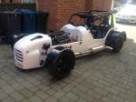
an interesting excersise, but as already mentioned that frame isnt complete, there are quite a few tubes missing footwell diagonals tunnel bars rear
suspension braces etc, as are all the gusset plates that are on a complete chassis i.e the steering rack which also braces the front end is missing,
also the steel tunnel, the steering column mounts cage mount gussets etc etc, the engine (used as a stressed member ) is not in position with any of
its mountings / tubes. i could carry on but the upshot is the screenshot represents a 75% complete chassis irrelavent of which cage / doorbars are
fitted so if those where taken into account its about 60% complete !!
quote:
Just wait until you see the rod ends in bending
a compromise admittadley but thats why they are all specced bigger than necessary if used in thier normal orientation i would be running 3/8ths all
round
cheers
marc
please email rather than u2u
direct workshop email ( manned 8am till 6pm )
www.mnrltd.co.uk enquireys to :-
chrismnrltd@btinternet.com
|
NOTE:This user is registered as a LocostBuilders trader and may offer commercial services to other users
|
ffrgtm
|
| posted on 1/12/12 at 08:42 AM |
|
|
quote:
Originally posted by big_l
Tbh this thread is useless unless you know every inch of a Mnr chasis and also factor in engine is used for strength !
A lot if people know everything on the Internet if they were that good why arn't they doing it for a living ??
Not aimed at anyone but just need to take it with a pinch of salt !!
Oh don't worry I'm right there with you, FEA results in solidworks are generally garbage anyways. That's why you do
"validation" afterwards. The one thing this method will allow you to do, is test different ideas and get real time feedback. The number
won't match up, but the trends generally will.
That said it's been very difficult to model the areas where two sets of tubes are bent and have their contacting radii seam welded. Meshing was
a nightmare. I still have difficulty imagining the reason that the chassis is done in this way... bending tubes and trying to make them line up like
this is usually much harder than the vastly more common, and most likely structurally superior method of joining members at a single node with a
single member bisecting another.
Marc, I'm sorry I don't have any good feedback for you yet... two engineering majors and an fsae car have put the MNR on the backburner

|
|
|