
Ditching the reverse box, measuring up for 2 piece prop
BigMac - 23/12/14 at 12:04 PM
Hi Guys
First post on here for quite a while, was hoping to call on my fellow BEC advocates for some advice.
With the Westfield off the road for winter, I've been looking into drivetrain options.
Have been reading more and more about ditching the reverse box and simply using a two piece prop. I'm very much an advocate of keeping things
simple, so removing the box not only saves me some weight, but also takes futher complexities out of the equation (that said, despite it being quite
noisy and harsh, I've never had any issues with the Quaife unit).
From what I've read on here and the conversation I had with Firow Propshafts in Holmes Chapel, I think I need to spec the following:
2 piece propshaft, 3 UJs with a centre bearing. Front prop (engine side) is a non TRT, non-telescopic. The rear prop (diff side) is a telescopic TRT
prop, with the slider nearer the diff.
The current setup (not including angles)

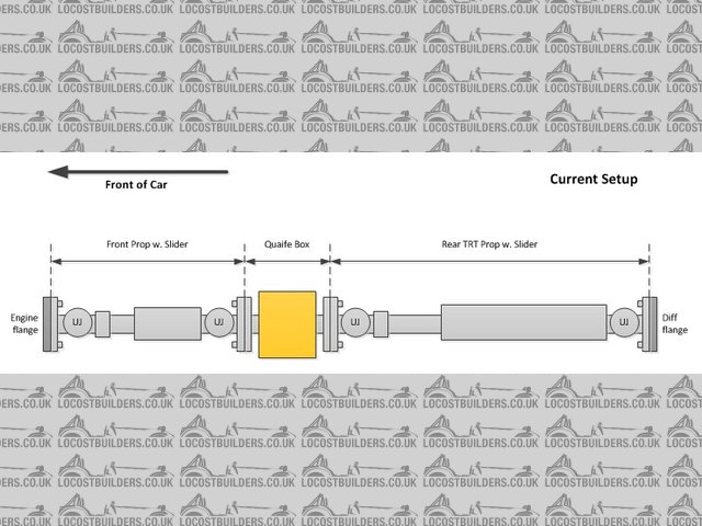
Description
The proposed setup (not including angles)

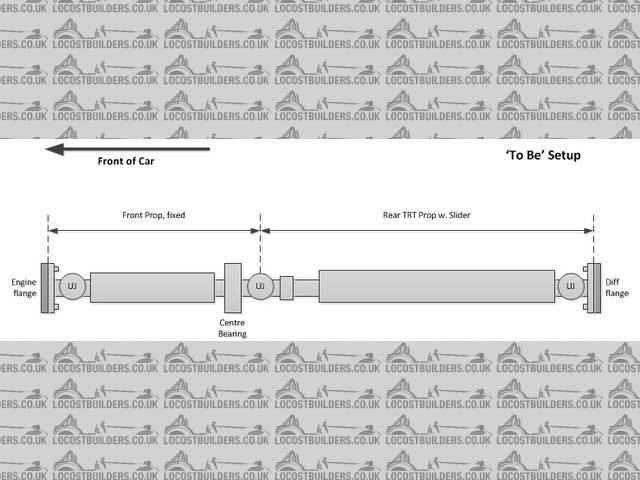
Description
The one thing I'm not sure about is angles and general measuring up, which is what I was hoping to get your advice on.
The chap from Firow has suggested I keep the engine side prop as straight as possible up to the centre bearing, apparently 2 degrees vertical is the
optimum angle. I'm not near the car right now, so I can't be sure, but I don't think it'll be possible as the tunnel isn't
flat on the top, it slopes downward. On top of that, it's quite a drop from engine to diff, so keep the first prop straight would result in quite
an angle for the second, diff side prop. Am I better to try and mount the props so there's a more gradual angle on both?
Either way, I'm sure you guys could do with some measurements to help understand the current setup- my plan was to measure from a straight edge
placed on the bottom of the chassis up to the centre point of the mounting flanges, that ultimately gives me the drop needed to go from engine to
diff. The one thing I don't really know how to measure is the horizontal plane- so if I were looking at the car from the back, what angle the
props would need to be at to go from the diff to the engine (in my case, slightly off to the right of the centre line of the car)... Or am I
overcomplicating it?
Last question for now- centre bearing, where abouts and how do I mount it? I've seen some examples where the bearing is mounted on its side
against a plate welded to the side of the tunnel, but apparently I need to mount the bearing flat on either the tunnel top or bottom. As such, would
welding a plate in be the best option, or could said bearing be mounted to an existing chassis rail? I have a feeling it's the plate option, but
wanted to see if anyone has done it differently.
Cheers in advance all,
Ben.
[Edited on 24/12/14 by BigMac]
mark chandler - 23/12/14 at 01:10 PM
The centre bearing sits in a big rubber doughnut so can be bolted to the floor, sides or top, on mine I just bolted to the side as it gave me the
straightest line to the back.
Do you have a sale price for the quaife box?
Cheers Mark
BigMac - 23/12/14 at 01:30 PM
Thanks Mark, did you bolt the bearing to the chassis rail itself or did you weld in a plate to mount it to?
I'll more than likely be selling the kit as a whole, so front telescopic prop, rear TRT telescopic prop and the reverse box. Props are currently
off being checked and balanced, with the box also just gone off for a service, did you want me to PM you when it's all sorted? I won't be
selling until the new prop is in and working though, so more than likely early 2015- January more than likely.
CosKev3 - 23/12/14 at 04:45 PM
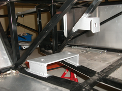

Description
As above, side mounted or top/bottom mounted will be fine.
MK side mount there's now, but earlier ones they mounted on the bottom.
On my Mac1 I'm converting to a bike engine I've made up a 'bridge' type thing for centre bearing, in pic above 
mark chandler - 23/12/14 at 06:54 PM
I welded a couple of tabs to the frame then bolted to these.
BigMac - 24/12/14 at 11:06 AM
So I managed to get some proper measurements last night, luckily the setup didn't seem as awkward as I remembered it...
According to my working, the drop from engine to diff in the vertical plane is 110mm over 1405mm, which makes a total angle of roughly 4.5 degrees if
both props were kept at the same angle (point to point).

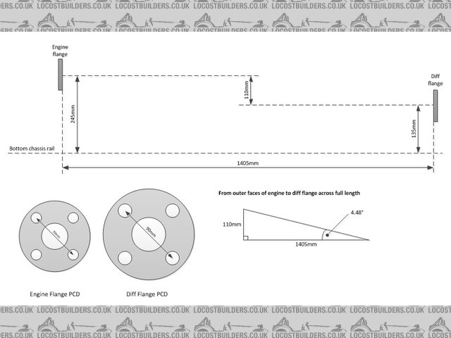
Description
I've drawn up another diagram to show what the angles may look like if I use a potential point to mount the centre bearing- keeping a 2 degree
angle on the engine prop as per the advice from the propshaft guys. The second prop would make an angle of roughly 5.4 degrees from the centre bearing
to the outer face of the diff flange, so obviously shallower if you factor in that the UJ will be further over than the centre bearing.

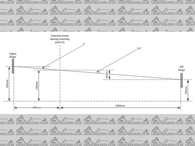
Description
What do people think about the angles, do they look ok? Is my maths right or have I missed anything critical in the calculations? Is the diff side
prop too long, is it worth mounting the props so that the angle remains constant over both of them?
Thanks again all,
Ben.
BigMac - 24/12/14 at 11:21 AM
Plus a couple of photos of the tunnel, was trying to capture the view from the diff perspective, to show the slight angle the props also need to make
to the horiztonal to meet the engine flange.

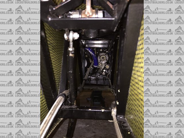
Description

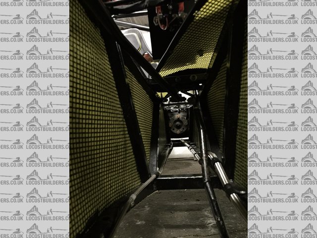
Description

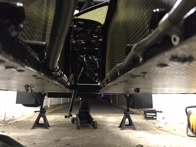
Description
BigMac - 26/12/14 at 07:42 PM
quote:
Originally posted by CosKev3


Description
... I've made up a 'bridge' type thing for centre bearing, in pic above 
Ah I see, what sort of angle will the prop be running from the UJ in the middle to the engine then?
CosKev3 - 31/12/14 at 09:05 PM
quote:
Originally posted by BigMac
quote:
Originally posted by CosKev3


Description
... I've made up a 'bridge' type thing for centre bearing, in pic above 
Ah I see, what sort of angle will the prop be running from the UJ in the middle to the engine then?
Will get a pic when next in garage.
I've converted a car engine chassis to fit the R1 eng,so it's all guess work/research on here I've used for prop alignment etc.
Basically just made sure none of the U/J's are running straight,they all have slight angles either sideways or height wise 
Fingers crossed it's ok! 
BigMac - 5/1/15 at 11:38 PM
Hi all
So I've done some more measuring up following conversations with Bailey Morris- was hoping to run another idea by you all.
As seems to be most people's issues, I'm still debating on centre bearing position.
I was looking for places to potentially weld in a new piece of box section on which to mount the bearing, main problem is there are no uprights
alongside the tunnel, they all run at an angle rather than 90 degrees to the floor of the car. As such, if I were to weld in box section it
wouldn't line up perfectly with the chassis members I was welding it to,. I could put a plate in along the side of the tunnel, but the prop guys
have said that the bearings are designed to be mounted horizontally and not vertically.
The potential solution is I have a single box section cross member 700mm from the diff flange, pictured here:


Description
I'm wondering whether I can bolt the centre bearing to this cross member, with the UJ being past the centre bearing (nearer the gearbox),
rather than before. The plan is to keep the rear prop (diff end) straight down the centre line of the car, rising 25mm over the 700mm to give me a 2
degree operating angle. If I were to do this, I'd need to mount the bearing 80mm above that cross member (taking into account where the centre of
the bearing is from its mountings). All in all that means I'd need two 80mm spacers, with decent bolts (I'm thinking M12) going through the
cross member, through the spacers, fixed to the centre bearing mountings with nylocks, all lock-wired in place.
I don't know, part of me thinks that 80mm spacers are just too long given the forces involved, even if they're solidly mounted. The only
other option I can see is welding in a plate either side of the tunnel, then welding in box section between these two plates at the right height,
which is level- no need for spacers.
However it's mounted, that results in a front prop of around 680mm that makes an angle of approximately 7 degrees when it hits the output flange
on the engine, which is just outside the optimum angles of 2-6 degrees.
Conscious the above is probably quite perplexing without pictures (I'm working on them!), but what would people do, weld in the plates and a new
piece of box section, or spacers?
[Edited on 5/1/15 by BigMac]
Hellfire - 7/1/15 at 08:20 PM
Once you start calculating propshaft angles it can all quickly become complex. In reality, the diff is fixed and the engine is placed in the most
suitable position for weight distribution and ground clearance, so the only real consideration is where to mount the centre bearing.....
The MK has a centre bearing mounting plate welded to the side of the tunnel. See
Davegtst picture here
The propshaft we have was converted by Dunning & Fairbank, to
incorporate a TRT in the rear section of the prop and the front section left as it was, including the sliding joint.
The first thing I would look at, is where Westfield place the diff mounting plate on their BECs which don't run reverse boxes and try to
replicate that. Failing that, I'd find a suitable place to weld a plate for the centre bearing which gives a straight horizontal run from the
bearing to the diff. Then manufacture and fit a prop catcher to ensure that if the prop does fail, it won't flail about in the tunnel.
I know you've already phoned a few propshaft manufacturers but we found Dunning & Fairbank to be extremely knowledgeable and helpful and they
might be worth another phone call...........
Phil
BigMac - 8/1/15 at 10:37 AM
quote:
Originally posted by Hellfire The first thing I would look at, is where Westfield place the diff mounting plate on their BECs which
don't run reverse boxes and try to replicate that. Failing that, I'd find a suitable place to weld a plate for the centre bearing which
gives a straight horizontal run from the bearing to the diff. Then manufacture and fit a prop catcher to ensure that if the prop does fail, it
won't flail about in the tunnel.
Great advice, I shall give Mark at Westfield a call and see if I can get a diagram/dimensions from him that may shed some light on where to put the
bearing. It's definately looking like a weld in plate job, so as you say at the same time I'm more than likely going to put a prop catcher
in at the bearing end.
quote:
Originally posted by Hellfire I know you've already phoned a few propshaft manufacturers but we found Dunning & Fairbank to be
extremely knowledgeable and helpful and they might be worth another phone call.
Nothing wrong with asking more questions if it means I can get it all working perfectly! I did try and call D&F but couldn't get through,
think I'll try them again this afternoon.


