

It doesn't sound like it is totally insurmountable, though (I am sure someone with relevant chassis/welding knowledge will be along soon with some advice), and just think of what you'll have when (not if...) you finish it.
Good luck
Simon

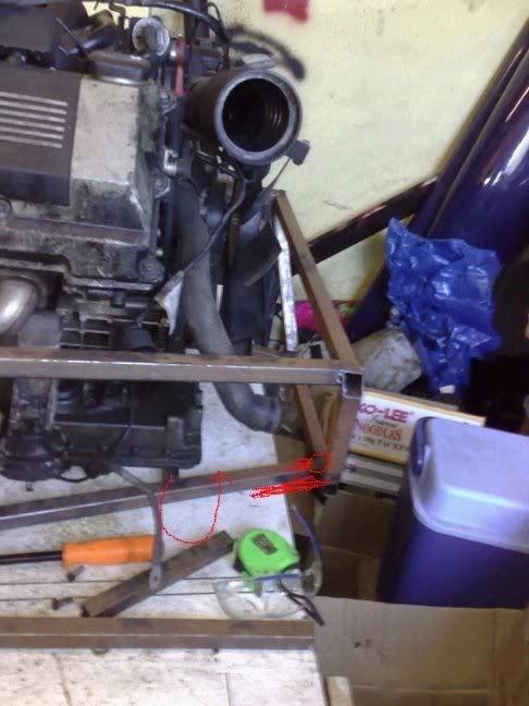
Ok, this afternoon I tried to lower the engine and gearbox into the half built chassis to take measurements for the transmission/prop tunnel.
The gearbox is too tall and doesn't fit between tubes Q and C.
The oil filter housing, mounted on the front left cylinder head makes the front of the engine to wide to fit in the bay. Even if it did fit the whole
lump is o big there is no room for anything else in there!
Can I cut tube Q (about 10" from the middle) and sort of bridge the gap over the gearbox? Or would that seriously weaken the chassis? Same thing
with tube J1, can i make a cutout from one side, plate the hole over and add some srtrengethening on the outside, or will that seriously weaken it
too?
Why oh why did I think I could make something interesting out of a (insert profanity here) BMW.
Not my best day in the garage today.
I feel sorry for you mate, but did you really think a BM V8 would just drop in 

It doesn't sound like it is totally insurmountable, though (I am sure someone with relevant chassis/welding knowledge will be along soon with
some advice), and just think of what you'll have when (not if...) you finish it.
Good luck
Simon
read your title and thought you had brought a westfield in kit form


regards wayno westy megablade owner
Thats the joy of trying to fit a quart in a pint pot and being a trailblazer. 


Don't just stand there and swear at it - go down to the pub, have a pint or two, sleep on it for a few nights and the answer will come to you.
 If it doesnt its time for the big hammer and a hacksaw.

Sorry - this doesn't answer your question but then i don't know what tube Q is as I'm sitting in the middle of a game park and
don't have the book with me but I do suspect that there are very few redundant members in the chassis so you better make sure you replace the
strength lost by altering any members or redirect the loads through some other suitably reinforced members.
[Edited on 5/11/08 by Ivan]
That is what heppens when you go against the 7 ethos. Add lightness, not a big whopping engine!
go down the tractor root and use the engine/transmission as a stressed member.
bolt/weld the suspension to either end of it, sorted


Never mind it'll be well worth the effort in the end, and it beats the easy way of fitting one of those tiny bike engine things.
Thanks guys - i'm feeling much better about it now.
Can I cut tube Q (about 10" from the middle) and sort of bridge the gap over the gearbox? Or would that seriously weaken the chassis? Same thing
with tube J1, can i make a cutout from one side, plate the hole over and add some srtrengethening on the outside, or will that seriously weaken it
too?
It would help if you posted some pics. Apart from anything else, without a diagram handy, it's difficult to know whiich tubes you mean
John
quote:
Originally posted by Daimo_45
That is what happens when you go against the 7 ethos. Add lightness, not a big whopping engine!
 We aren't building 7's, we're building Locosts (mostly) which is completely different and means if you want to build
a car that weighs 200kgs powered by a hairdryer engine, then I'll take the pee, but help if I can, and conversly if I, or the op want to build
car to sink a battleship then we expect the same
Diagrams would indeed be helpful, You can chop about loads of stuff if you want, the secret is in triangulation.
So assuming Q is the bar over the top of the gearbox that sounds like a fundemental tube, but if you were to remove you could replace with a V brace
going back to the tube behind.
Then add a few gussetts for good measure, something like this.
Alternatively make a matchstick model, chop out the bits you need to lose and see how it flexes, add in some additional bars until it feels good
again.

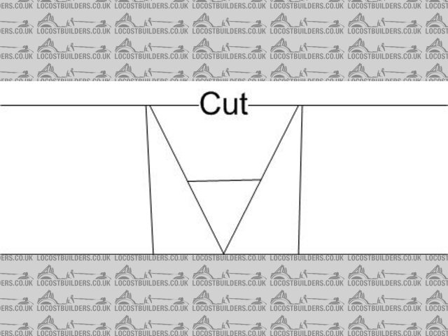
Rescued attachment Drawing1.jpg
Don't forget you can use bolt in tubing as well. I have 6 diagonals (some attached to ea other) that are bolt in to allow me to remove my
engine/trans. And yes, my engine/trans are far bigger than req'd  .
.
Cheers.
I had the same problem but did as above. You may find there are other tubes that are in the way. All you do is make sure you have enough triangulation
around to make up for the lost strength 
Can't you cut the lower bar instead of the upper one? Cutting the upper one is going to cause problems too isn't it? That's what I did to make my Nissan CA18DET fit. The transmission housing just BARELY misses the upper bar, so it's back as far as possible. It's also bolted to the lower tunnel to hold everything.
Would replacing the Q tube with a cross give you enough room? That's what I did to accommodate the desired far-back-ed-ness of my engine. Have
a look in me photo archive as i'm not sure how to post one from there on here!
Liam
Can't offer any advice other than to say I faced similar problems trying to slot in my Volumex engine.
Once the initial shock/horror of the frikking thing not fitting you'll no doubt think around it - just requires a bit of lateral thinking and
perseverance.
Cheers, Pewe 
I'm trying - very, very hard - to not trout-slap you outside the head.
So it went something like this:
1. The frame was built per published plans.
2. A big drivetrain was acquired and dropped in.
3. You're unhappy and frustrated that it doesn't fit.
Where in these steps was the planning, the foresight, and thinking ahead? Where is the project management? I'm sitting here just shaking my head
wondering how on earth it could turn out any other way.
What's next, dispair that the sofa recliner won't fit as a seat and how unfair that is? I'm sorry to come down on you so hard, but at
some point, you, all by yourself, are 100% responsible for how this stuff fits together and no one else. Time to step up, take responsibility, and
plan things out ahead of time.
1. Mcsorley +4 chassis plans have been followed thus far.
2. BMW 530i had previously been bought and stripped. All parts were measured up, engine will fit in chassis, oil filter housing had been removed
previously but when refitted found it fouls a top rail.
3. Gutted it doesn't fit, turn to a generally great forum for help and find some great ideas, somewhat overshadowed by patronising and mocking -
this step had not been planned for.
Thanks to all those members who have posted geninely helpful advice.
I'll find a way around this and build it just to prove all the doubters wrong!!!
[Edited on 6/11/08 by aerosam]
I am putting a P76 V8 into a standard locost frame. Its a chubby cousin of the rover V8.
Perhaps look at a remote oil filter. I know nothing about Bimmers but surely something could be adapted with a sandwich plate.
I had to take out that same bar and I just moved it back to where it would fit. There is no triangulation in it but I am not fussed.
You could move it back as I did and perhaps put in a removable bar held by rod ends thats up high. Isnt perfect but such is life. Also aids in getting
the thing in and out later on.
Another thing you can think about is the Aussie mod below the gearbox. Its a bent tube that follows the gearbox. It works.
Ive been through exactly what you are going through and its all about compromise. There will be plenty more of these moments though so try not to let
it get you down. Its good fun finding a way around it.
Good luck.
Cheers
Damian
At least it's a home-made chassis, so cutting a piece or two off and relocating won't be too bad.
It's still an awesome project, so accomodating an oil filter is not the end of the world.
Good luck with the fix, and have fun!
cheers,
David
P.S. Don't be too hard on kb58 - in your initial post it did sound like you had been over-ambitious in your project and had run aground. Only
when you added more info did it become apparent that you were fully aware of the nature of your project! 
[Edited on 7/11/08 by David Jenkins]
Regardless of what level of thought or planning was put in beforehand, a colleague of ours has posted his frustration asking for some help. Who are
we to take the wee out of someones ability or experience? The point is, hes making an effort to push limits, and build something unique.
A remote Oil Filter Housing on the bulkhead sounds good, as does removeable sections. Try looking at the possibilities of a completely removeable Q
and P sections, and anything else above - ie the scuttle.
This will allow a bit more room when removing the Transmission, and will allow the bellhousing to move around slightly without pushing the frame
around whilst taking it out. Could also prove usefult if chaning a clutch.
The idea of using the transmission itself as a structural member is another goodun. Are there any mounting points you can use?
Im fitting a 2.9 V6 in mine, and im going to have to have a remote oil filter, and take everything off the engine that i can, and mount it somewhere
else, purely to keep the bay tidy and accessible.
All the best with the build, and read the negative responses if they appear. You can always choose to ignore them afterwards. All feedback is good
feedback, and the negative ones are just one persons opinion.
Don't worry about it! I've made that mistake so many times, that I no longer make 'plans' until I've collected all the parts
I want to use!
Once I've decided on the parts, then I start to scratch my head to see how 'x' can be modified to accept 'y'. It's
great fun and will give you a real buzz once you've nailed it (not literally  ).
).
Nothing is insurmountable... there will be a solution. Post some pics and we'll see where we can help!
quote:
I'll find a way around this and build it just to prove all the doubters wrong!!!
There's always a way around problems. It just takes lots of careful planning and designing.
panic over, it just about fits!
I'm going to have to chop a little (ok a lot) from the centre of the top rail immediately behind it to allow the gearbox to fit.
I'm a little concerned with how tall it is, are you allowed to have the engine poking through the bonnet, if it has a nice smooth plastic engine
cover over it? (the BMW one from the donor is actually quite nice)

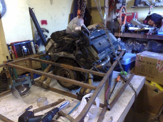
Rescued attachment engine in small.jpg
just about enough clearance up front for the steering rack to go. Don't know if i'll ditch the big fan yet as theis beast is going to need
as much cooling as possible.

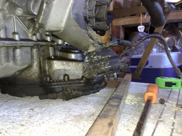
Rescued attachment engine in mount small.jpg
dammit wrong picture that one was showing the engine mount, I think I may have to ditch the original rubber (as shown) as it will protrude out the
side of the car. What are the downsides to mounting without rubber bushings?
Here's the pic of the front:

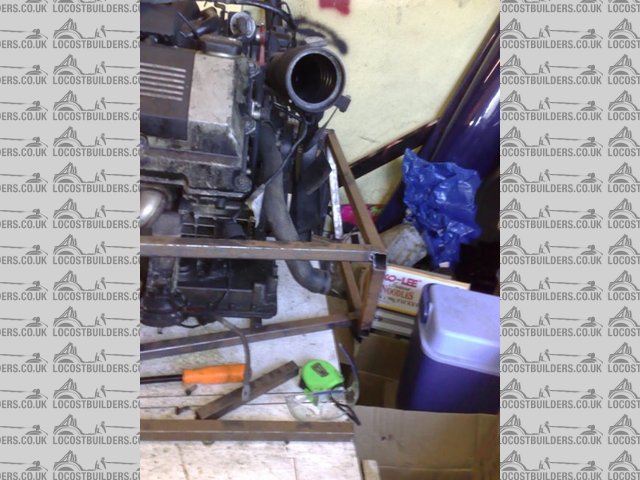
Rescued attachment engine in 2 small.jpg
Before going further, are 1" tubes going to be strong enough? A V8 has around 300 ft-lb of torque, and a hell of a lot more once it goes through
the tranny. You might want to consider 1.25" or even 1.5" tubing, and/or lots of trangulation. Consider putting a 12" bar through the
engine mounts and applying 1000 lbs load to it, that's about what they'll see.
About it being tall, make that a feature. It's not a bad-looking engine up top, might look really nice with the BMW logo.
[Edited on 11/12/08 by kb58]
are you going to fit the engine at the height you have on the pics?
Your chassis is sitting on the floor!
Try paking the chassis rails with 2" blocks to raise it up, that will lower the engine a little.
Yes you should have built the tunnel & the assoc. tubes after the engine had been placed in position, but no ones perfect
I I were you I would place the engine in position by cutting out the offending rails.
Then carefully look at what you have, maybee post some pics, & build strength in where necessary.
BTW love the fact that you don't follow the pack.
Despite the fact that a hell of a lot are building 'mecano' kits, this site is & always will be LOCOST builders
Couple suggestions:
- offset engine as far to the passenger side as possible
-lower engine in chassis a bit
-triangulation. Seriously, you will need it.
-bolt in triangulation. Allows you to get as much stiffness as possible and still get the big lumps in and out. I use 6 bolt in tubes on mine (not
completed yet).
-watch the foot room. I see your starter is on the drivers side (assuming it's a RHD).
Good Luck.
quote:
Originally posted by aerosam
dammit wrong picture that one was showing the engine mount, I think I may have to ditch the original rubber (as shown) as it will protrude out the side of the car. What are the downsides to mounting without rubber bushings?
ok heres some more explanation
The chassis is only in VERY early stages don't worry, LOTS of triangulation is going to be added. As I'm doing something quite different, I
only built it to a stage that could be completely undone without wasting too much steel if it clearly wasn't going to work.
The engine can't go any lower, if you look at the pic of the front of the engine, you'll notice the sump actually extends forwards, there is
only a 3/8" clearance to the tube passing underneath.
The starter is actually on the passenger side, I guess the engine has that shape on the reaer flange to allow the starter to be fitted on either side
depending on whether the car is LHD or RHD. And yes mine is going to be RHD.
Also - I had no idea the engine could be offset. That may be a great idea to create more space for the pedal box. However I would be concerned that
the car may list to one side and may not handle well.
As far as the engine mounts go, i think I may have no choice but to stick with the originals, as the one on the passenger also forms the alternator
bracket, and has the 2 pipes to the oil filter passing through it.
I suppose I could make panels that would be about 1" from the chassis at this point - almost everything else on this car will be different to the
book - so why not?
and here's a pic of the engine (not mine - wish is was that clean) with the top cover on. If I can have this poking through the bonnet and still
comply with SVA I think it would look really nice.
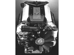

Rescued attachment m60b40a.jpg
The BMW engine has far more clearance than my v8 I reckon. Chop that bar where the bell housing will go obviously. You wont regret it.
What I have done to move the engine back is put the pedal assembly inside the cockpit incl the master cyl but using remote reservoirs. That frees up
space.
As for worrying about the left engine mount and the alternator bracket, one thing I was toying with (I am running with no alternator at all now as its
a track car) was running the alternator off the tail shaft (I think you guys call it the prop?). If you build the tunnel high enough right before the
rear bulkhead then it would fit pretty easy. It would be a matter of playing around with pulley sizes to get the best out of it though.
If you want to see pics of my chassis let me know.
Cheers
Damian
quote:
Originally posted by aerosam
Also - I had no idea the engine could be offset. That may be a great idea to create more space for the pedal box. However I would be concerned that the car may list to one side and may not handle well.
Hi,
With regard to the engine mountings I had similar problems with them sticking out too far on the Rover V8 lump.
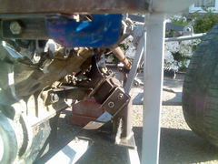
Although I used the SD1 steel mounts I had to cut and shut them to bring the ends closer into the engine. Wouldn't be difficult to fabricate mild
steel mounts from scratch though - that's what I've done on my Zetec build. Pic of how I did the V8 below - I then fabricated up my own
mounts to weld to the chassis.
[img]

Engine Mounting 3
[/img]
Hope that helps some. Loads more pictures on my webite if you click on the link at the bottom of this post.
Cheers,
Mart.
One easy(ish) solution to the fact that, as shown you will probably need to sit on a pillow to see over your engine would be a dry sump kit. You could
locost your own or they are available from www.vacmotorsports.com. Then all you will have to do is to work out where the oil tank will fit.
Lowering the engine has handling advantages and might help with your gearbox tube hassles.
It looks like you are having fun!
But be aware that most transmission bellhousings (assuming it's manual) hang down just as far as the bottom of the pan, so the drysump only fixes
half the problem. Small-OD flywheels and multi-plate clutches can fix that, at a price.
[Edited on 11/14/08 by kb58]
I'd make verey effort to lower the engine!! Make a new alternator/engine mount and do whatever it needs to get the centre of the crank pulley, to
somewhere near the front lower rail!
I had all the usual big engine, small space thing with my engine. I chopped and welded the sump making it 2" shallower and the same depth as the
bellhousing. I binned the original alloy engine mounts and made steel ones. I made a take-off for the oil to remote the filter (and fit a cooler and
Accusump). I binned the chunky ally alternator mount and made a smaller steel one. I made tubular manifolds so the steering column could pass through
it! I extended the inlet runners and turned them 180 degrees so that it pointed forwards instead of into the pedal box. Then I had to make an
extention for the plenum as the butterfly housing fouled the cam pulleys. I had to lose the oil filler cap on the N/S rocker cover because it was
hidden under the resited plenum, so now I have to top-up through the breather on the O/S!
I had to mix and match the clutch componenets to get the Alfa to play with the Ford.
All these things are what makes my car what it is. It's a pile of rubbish to most folks, but to me, it's been a fantastic oppertunity to
prove to the doubters (and myself) that it was/is possible.
Keep asking questions. Even if they appear daft. Expect to get some unhelpfull, sarcastic or rude comments but just roll with 'em! Listen to what
folks are saying and pick out the bollox from the sensible to make up your own mind. If your questions havn't been answered, or you're still
not sure, ask again!
Most of all, enjoy.
Amen.
thanks owelly but unfortunately I can't lower it any more, the sump is cast ally and i don't have the skills/equipment to modify it, also to lower it any more would require considerably more chopping of the chassis, and to be honest I don't want to weaken it any more.
Just a quick update - I've chopped a section of the top tube behind the engine and trial fitted the engine and box together. I'm happy that
it fits ok, will just require a little more fettling to get the gearbox to sit properly.
So in my short 1 hour sessions (longest i can get without getting on the wrong side of the wife) over the last few days I have been TIG'ing up a
lot of the joints that were previosly tacked or completely unwelded to stiffen the whole thing up so when I make any further chops I can be sure the
chassis won't be distorting.
Lower the engine - absolutely essential, for two reasons. One is handling and other could be a major prob if you don't.
When I did my first SVA, the examiner failed my original bonnet scoop on the line of sight requirement, so I had to rehash the bonnet.
If you have to start faffing around lowering your engine for the same reason, it'll be a hell of a lot of work.
I have about 2" under sump guard
There's plenty of peeps on here who can weld ally, and I'm sure they'd volunteer. I would be our AC/DC tig got melted in a fire last
year!
ATB
Simon
Thanks for all the advice guys, and I i'm not just disregarding it, but I really CANT lower the engine any more.
Where the sump protrudes forwards, it just clears the tube in the front of the engine bay. To lower it any more would seriously weaken the chassis,
and also mean I have nowhere to mount the engine to as the 2 tubes running through the engine bay from it to the back have nowhere to go.
I've measured it and it's 13" proud of the chassis top rails at it's highest point. The standard scuttle is 10" tall.
Can't I just make the scuttle 3" taller, the same with the nosecone and make my own bonnet to fit?
Line of sight would have to be sorted with seating height. By the way, what are the requirements for it and how is it measured? Or is it simply down
to the examiners discretion?
Wouldn't it be wise to do a new chassis all over again after you finish with the trial fitment?
I think I'd sooner dump the engine and use something else. Seriously, the thought has crossed my mind.
I can't see any BMW engines to be used for locosts. The engines are absolutely massive, even the 2L straight six ones.
quote:
Originally posted by aerosam
I think I'd sooner dump the engine and use something else.
quote:
Originally posted by l0rd
I can't see any BMW engines to be used for locosts. The engines are absolutely massive, even the 2L straight six ones.

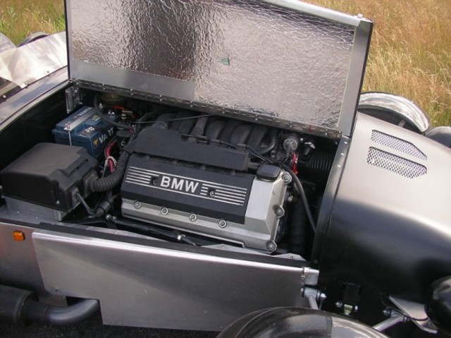
Or how about a straight 6?

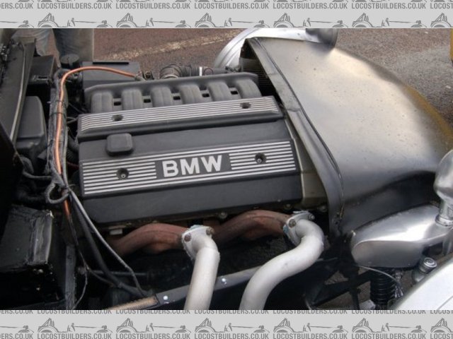
Rescued attachment BMW5small.jpg
I wasn't trying to suggest it couldn't be done, but that maybe the time, effort and cost of going from where you are at the moment, to where
you want to be, might outweight the benefits of getting there.
I think if I was in your situation, and still keen to use that engine, I would be inclined to start again, by mocking up the engine position plus all
the necessary ancillaries, then making up a suspension bracket jig, then basically constructing the chassis around them.
It's a drag to have to cut up a chassis, but it will provide most of the tubes you will need.
Just a thought, but sometimes it is better to take a couple of steps back before starting again
John
i think you would be better off with a 442 chassis .
ive been through all that you have, just trying to make my volvo engine fit .
the extra 2 inch chassis height allowed my engine to sit further back .
i started with a std chassis , realised that the engine was going to be too far forward (like yours is , but not as bad) and make for really bad
handling .
but you have to try it first to see what happens even if youve done all the measuring in the world .
its at this point where you realise that , if you go any futher with this project you might aswell build the chassis around your chosen donor , and
fit full bodywork on it - it makes the whole process easier , and in the end you can see why lots of kit manufacturers in the 70/80s made stuff like
they did , and you dont have to start modifying parts of the engine just to get it to fit .
perhaps im not explaining myself properly when i say that , but if you look under a stylus - its right there for you to see what you should be aiming
at .
Just going to measure height of my engine etc
Right, tops of my rocker covers are under 6" above top rail, and plenum top is bang on 12".
ATB
Simon
[Edited on 23/11/08 by Simon]
Ok, I would move forward the one under the sump, and the outer bottom chassis out by the minimum required.
The area formed under where the steering rack goes can be fully welded sheet, and you can add triangulation from top sides and front of you're
concerned about how far forward the "sump" piece has been moved.
Going from the pics of the BMW powered car, you need your rockers slighly above top rails, that should give you an idea. Where di you get the pics
from and are there more (if from the web) showing the build. Might be even more help if they are available.
Re your engine mounts, you'll need to get rid of them as you need space for exhausts and steering column, so make them smaller and not so over
engineered. My engine is held up by two 1.5" 16 swg tubes welded to the chassis and modified Rover mountings
On more thing - bin the BMW fan and use something a bit more modern, that'll give you another couple of inches
ATB
Simon
PS If no go, I've got 50 quid for the engine and box (delivered) 
[Edited on 24/11/08 by Simon]
quote:
Originally posted by mr henderson
I think if I was in your situation, and still keen to use that engine, I would be inclined to start again, by mocking up the engine position plus all the necessary ancillaries, then making up a suspension bracket jig, then basically constructing the chassis around them.
Mr Henderson,
the pics were in response to l0rd's comment that all BMW engines were unusable in Locost applications - no offense intended.
quote:
Originally posted by Simon
Just going to measure height of my engine etc
Right, tops of my rocker covers are under 6" above top rail, and plenum top is bang on 12".
ATB
Simon
[Edited on 23/11/08 by Simon]
quote:
Originally posted by kb58
[Regarding the pictures showing BMW lumps in the cars, what's unknown is how stiff the resulting chassis is. Just because they fit under the hood doesn't mean the rest of the design worked out. The pan may hang way too low and critical structures may have been removed to make it fit.
OTOH it may be very well thought out and be just as strong as a standard Locost chassis. Any chance you can contact the owners of these cars and quiz them on their decisions?
[Edited on 11/24/08 by kb58]